- Instrument Earth (IE) and Signal Grounding
- Why Instrument Earth Matters in PLC and DCS Systems
- Instrument Earth (IE) vs Safety Earth (PE) – Key Differences
- Sources of Electrical Noise in Industrial Plants
- Practical Methods to Reduce Electrical Noise
- Basic Principles of Instrument Earthing
- Instrument Earthing in PLC and DCS Systems
- Cable Shielding and Shield Termination Best Practices
- Typical Instrument Earth System Arrangement (Field → Control Room)
- Instrument Earth Bus Bar in Control Panels
- Installation Practices for Instrument Earthing
- Common Problems Caused by Poor Instrument Earthing
- Troubleshooting Instrument Earthing Issues – Step-by-Step
- Best Practices for Reliable Instrument Earthing
- Periodic Inspection and Maintenance of Instrument Earthing Systems
- Ensure Signal Integrity with Proper Instrument Earthing
Reliable signal transmission is very important for accurate measurement and consistent control in today’s industrial automation systems. Instruments including transmitters, analyzers, control valves, PLC systems, and distributed control systems (DCS) are very important for process facilities to keep an eye on and control their operations. These instruments work with very weak signals, and even tiny electrical problems might cause measurement mistakes or make process control unreliable.
Instrument Earth (IE) is a vital way to keep signals accurate and safeguard instrumentation equipment from electrical noise. Some people call Instrument Earth Electronic Earth, Clean Earth, Reference Earth, or Signal Earth. Its main job isn’t to keep people from getting shocked by electricity; it’s to make sure that sensitive electronic equipment used in measurement and control systems has a steady electrical reference.
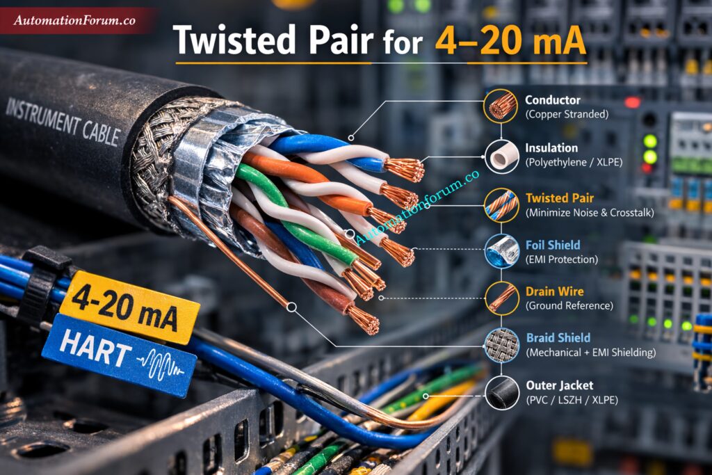
Master Twisted Pair Cable for Industrial Signals: Twisted Pair Cable in Industrial Signal Transmission: The Essential Guide for 4-20 mA and RS 485 Systems
Instrument Earth (IE) and Signal Grounding
Instrument Earth (IE) is a special grounding system for control and instrumentation equipment. It provides a stable reference potential for electronic circuits that handle measurement and communication signals.
Most instrumentation signals in process industries operate at low energy levels. Examples include:
- 4–20 mA analog signals
- HART communication signals
- Digital input and output signals
- Fieldbus communication networks
- Analyzer measurement signals
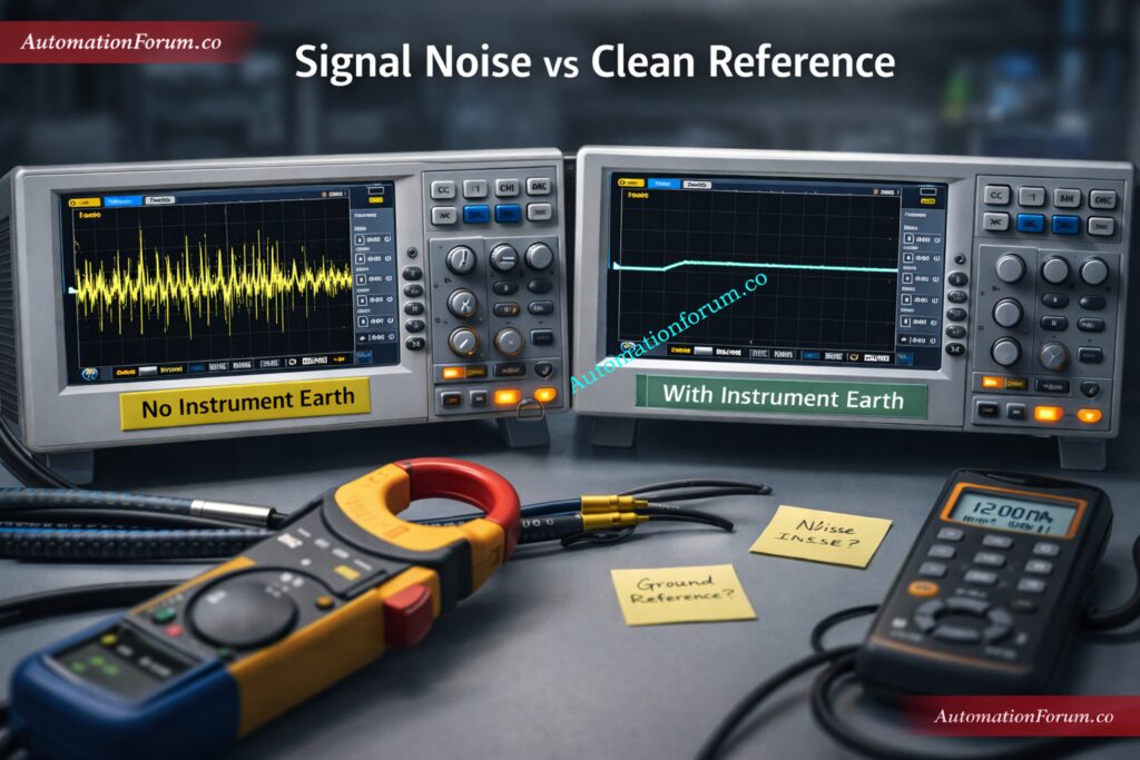
Because these signals operate at very small voltage or current levels, they are vulnerable to electrical interference. If electrical noise enters the signal path, it can distort measurements and cause incorrect process control decisions.
Instrument Earth helps prevent this by maintaining a clean and stable reference point for all instrumentation equipment.
Troubleshoot 24VDC Signal Problems Like an Expert: Why 24VDC is Not Always 24VDC – Real-World Troubleshooting for Analog and Digital Signals
Why Instrument Earth Matters in PLC and DCS Systems
How Instrument Earthing Improves Measurement Accuracy
Industrial plants contain many sources of electrical interference. Large motors, variable frequency drives, transformers, welding machines, and power cables generate electromagnetic noise that can couple into instrumentation cables.
Without a proper earthing system, this noise may enter measurement circuits and create several operational problems.
Impact on Control Loop Stability and Communication Reliability
Some common problems that happen when earthing isn’t done well are:
- Inaccurate measurements: Electrical noise can change the shape of analog signals, like 4–20 mA loops. A slight adjustment can modify the temperature, pressure, flow, or level that is being measured.
- Error in communication: Modern instruments talk to each other using digital protocols like Fieldbus, Modbus, or HART. These signals can get messed up by electrical interference, which can lead to communication problems.
- Control loops that aren’t stable: If noise causes measurement signals to change, the control system might not work right. This can make control loops oscillate and processes run in an unpredictable way.
- Unexpected equipment trips: Alarms or safety shutdowns may go off even when the operation is running smoothly if the indications are wrong.
Instrument Earth lowers these dangers by giving instrumentation equipment a separate, low-noise grounding reference.
Why 4–20 mA Still Dominates Automation: Why Engineers Still Trust the 4-20 mA Signal in Automation Systems
Instrument Earth (IE) vs Safety Earth (PE) – Key Differences
There are two types of grounding systems used in industrial plants: Instrument Earth and Safety Earth. They are not the same thing.
Safety Earth keeps humans from getting shocked by electricity, and Instrument Earth keeps sensitive instrumentation signals safe from noise and interference.
| Aspect | Instrument Earth (IE) | Safety Earth / Protective Earth (PE) |
| Primary Purpose | To maintain signal integrity and measurement accuracy in instrumentation systems. | To ensure human safety by preventing electric shock during electrical faults. |
| Main Function | Provides a clean, noise-free reference ground for sensitive electronic instruments. | Provides a low-resistance path for fault current to flow safely to earth. |
| Current Flow | Normally carries little or no current. Only leakage or induced noise may be present. | Carries fault current during insulation failure or electrical faults. |
| Equipment Connected | Instrument transmitters, analyzers, PLCs, DCS panels, signal conditioners, cable shields, and instrumentation circuits. | Motor frames, electrical panels, switchgear, transformers, metallic enclosures, and equipment bodies. |
| Noise Consideration | Designed to minimize electrical noise, EMI, and ground loops affecting signals such as 4–20 mA, HART, or digital communication. | Noise reduction is not the main objective; safety is the primary concern. |
| Ground Quality Requirement | Requires a very clean and stable earth reference with minimal interference. | Requires low resistance grounding mainly to safely dissipate fault currents. |
| Connection Points | Usually connected to instrument grounding bars inside control rooms or marshalling cabinets. | Connected to main earth bus bars, equipment frames, and structural grounding systems. |
| Wiring Practice | Often uses dedicated insulated grounding conductors and isolated grounding systems. | Uses green/yellow protective earth conductors bonded to equipment chassis. |
| Shield Grounding | Cable shields of instrumentation cables are usually terminated to instrument earth to prevent noise. | Cable shields are not typically connected to safety earth for signal systems. |
| Impact if Poor Grounding | Can cause signal noise, unstable readings, communication errors, and instrument malfunction. | Can lead to electric shock hazards, equipment damage, or fire risks. |
| System Separation | Usually kept separate from safety earth wiring paths to prevent electrical noise interference. | Part of the main electrical grounding network across the facility. |
| Final Ground Connection | Eventually bonded to the main grounding grid at a single reference point in most plants. | Directly connected to the main plant grounding grid. |
| Typical Location in Plants | Control rooms, instrument cabinets, DCS/PLC panels, analyzer shelters. | All electrical installations such as MCC rooms, motors, field equipment, and panels. |
Learn Critical Signals for Emergency Valve Shutdown: Signals for Emergency Valve Shutdown in Critical Processes
Key Practical Insight (Industrial Plants)
In most process industries (refineries, petrochemical plants, power plants):
- Instrument Earth = Clean Earth
- Safety Earth = Fault Protection Earth
Both systems are kept separate in routing but bonded at a single point to the plant grounding grid to prevent ground loops and interference.
Solve the Dead Zero Problem in Analog Signals: Beyond Zero: Understanding the Dead Zero Problem in Industrial Analog Signals
Sources of Electrical Noise in Industrial Plants
Common Noise Sources (Motors, VFDs, Welding, Lightning)
Industrial settings are electrically loud because a lot of electrical and electronic gadgets create electromagnetic interference (EMI) that can mess with signal transmission and instrumentation systems.
Some common sources of noise are:
- Large induction motors
- Variable Frequency Drives (VFDs)
- High-power switching devices
- Transformers
- Power distribution panels
- Welding equipment
- Lightning strikes
- Static electricity buildup
Simulate 4–20 mA Signals with a Loop Calibrator: How to simulate 4-20ma signal with Loop Calibrator ?
How Noise Couples Into Instrumentation Cables
- These devices create powerful electromagnetic fields that might cause unintended voltages to appear in neighboring instrumentation connections.
- These induced voltages can cause signal distortion, unstable readings, communication problems, and wrong process measurements in control systems like PLC or DCS if they are not properly shielded, routed, grounded, and instrument earthed.
Follow the 4–20 mA Loop Verification SOP: Live Signal Verification 4 to 20 mA Loop Standard Operating Procedure (SOP)
Practical Methods to Reduce Electrical Noise
Industrial automation systems use several engineering techniques to reduce electrical interference and maintain signal quality.
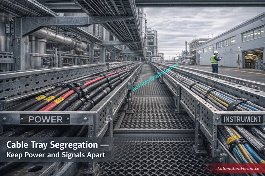
- Separate instrumentation cables from high power cables and motor feeders whenever possible.
- Use shielded twisted pair cables for analog and communication signals.
- Make that the ground wire shields are properly connected to the instrument earth bus bar.
- Put surge protection devices in places where lightning or switching surges are likely to happen.
- To lower electromagnetic coupling, use the right cable trays and metal conduits.
- To make sure the electrical reference is stable, make sure that solid grounding techniques are used throughout the facility.
These methods make instrumentation systems far more reliable and accurate.
Test Your PLC Analog Output Troubleshooting Skills: Troubleshooting Analog Output Signals in PLC Loops – Advanced Scenario-Based Quiz for Process Industries
Basic Principles of Instrument Earthing
- Give the instrument its own ground, independent from the power ground. This dedicated earth keeps a low-noise reference for sensitive signals and stops power fault currents from messing up measurements.
- Make sure that all of the instruments have the same ground reference. When transmitters, sensors, and I/O modules all use the same reference, measurement offsets and common mode errors are less likely to happen.
- Controlled single point bonding can help you avoid ground loops. If you have to make more than one connection, employ isolation or bonding methods that keep currents from flowing across signal shields.
- Correctly connect the cable shields to the instrument ground. Proper termination routes captured interference to earth instead of into signal conductors.
- Use low resistance, short bonding leads. Short direct bonds between shields chassis and the instrument earth bus reduce loop area and lower induced noise.
- Route instrument earth conductors away from power runs. Physical separation from motors VFD runs and power trays reduces electromagnetic coupling and induced voltages.
Understand Redundant Transmitters and Voting Logic: Redundant Transmitters Explained: Reliability, Voting Logic and SIL for Instrumentation Engineers
Instrument Earthing in PLC and DCS Systems
- Centralize instrument earth in marshalling or control cabinets. An instrument earth bus bar inside the cabinet provides a single tidy point for shield and chassis terminations.
- Connect cable shields chassis and signal returns to the same earth bus. This ensures I/O modules receive consistent reference voltages and avoids measurement drift.
- Size grounding conductors so that they have low impedance even when the conditions are changing. When there are strong transient currents elsewhere in the plant, proper sizing keeps potentials steady.
- Use isolation modules when long runs risk loop formation. Signal isolators maintain accuracy without breaking safety or overall bonding requirements.
- Label earth terminals clearly for maintenance and testing. Clear labeling prevents accidental cross connections that reintroduce loops or noise.
Ground Your Instrumentation System the Right Way: How to properly ground an Instrumentation System to reduce noise?
Cable Shielding and Shield Termination Best Practices
- Use continuous shields with a reliable drain conductor. A continuous shield intercepts external fields and drain wires provide a consistent connection to instrument earth.
- Terminate shields at the appropriate end according to project rules. Single end termination at the control room is common to avoid creating a shield current path that forms a loop.
- Prefer individual pair shields for low level analog pairs. Separate shields reduce crosstalk and protect microvolt level signals better than an overall shield alone.
- Use overall shields for long multipair trunk cables. Overall shields protect grouped signals during long runs from junction boxes to the control room.
- Inspect shield continuity and bond quality during commissioning. Poor shield continuity is a common root cause of EMI problems and must be verified with tests.
- Avoid bonding shields to random structural steel or piping. Bonding to arbitrary metal can create unpredictable noise paths and upset instrument references.
Use the Control Valve Noise Calculator Now: Control Valve Noise Prediction Calculator – IEC 60534 Based Engineering Tool
Typical Instrument Earth System Arrangement (Field → Control Room)
- Field instruments connect to local junction boxes then to trunk cables. This staged routing collects signals while preserving shield continuity and ease of maintenance.
- Trunk cables terminate in marshalling panels or control cabinets. Inside these enclosures shields and chassis grounds meet the instrument earth bus.
- Instrument earth bus links to the plant grounding grid at a controlled single point. Single point bonding helps control loop currents while still allowing a fault path to the main grid.
- Dedicated earthing conductors carry the instrument earth to the main grid. These conductors should be routed separately from heavy current conductors.
- Use signal isolators or common mode filters where layout or long runs demand. These devices help maintain signal integrity when perfect routing cannot be achieved.
- Include the earthing topology in the as-built drawings. Keeping accurate records makes it easier to fix problems and stops people from making changes that make noise by unintentionally.
Detect Noise Issues in Control Signals: Noise and Signal Stability Observation for Running Inspection in Instrumentation and Control Systems
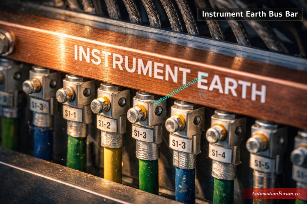
Instrument Earth Bus Bar in Control Panels
Inside PLC and DCS control panels, the instrument earth bus bar serves as the main grounding reference for instrumentation equipment.
Usually, this copper bus bar is installed within system cabinets or marshalling cabinets and connected to the plant’s grounding grid via special earthing conductors.
The instrument earth bus bar is a place where all of the following can connect:
- Cable shield terminations
- Instrument chassis grounding
- Signal reference grounding
- Control system electronics grounding
For automation systems to send signals reliably, it is important to keep this connection clean and low resistance.
Check If Your Home Earthing Is Safe: How to check if the earthing is properly done in our home?
Installation Practices for Instrument Earthing
- Plan earthing and cable trays early on in the engineering process. Early planning avoids retrofits that are often noisy and expensive to correct.
- Segregate instrument and power cable trays and avoid long parallel runs. Physical separation is one of the simplest and most effective noise reduction measures.
- Terminate shields to designated instrument earth terminals only. Using designated terminals keeps shield drainage consistent and avoids ad hoc bonding.
- Keep bonding leads short straight and mechanically robust. Long looping bonds increase susceptibility to induced voltages and may corrode over time.
- Use corrosion resistant lugs and label all connections. Good mechanical connections preserve low resistance and make maintenance safe and quick.
- Perform continuity and resistance checks after installation. Checking low resistance paths and shield continuity before commissioning stops a lot of problems from happening later.
Learn What an Earth Fault Really Means: What is an Earth Fault?
Common Problems Caused by Poor Instrument Earthing
- Analog readings that change and measurements that drift. Noise and common mode voltages can randomly alter reported values and upset control loops.
- Communication failures and intermittent data loss. Induced interference on communication pairs causes retries packet loss and network instability.
- False alarms, trips that come out of nowhere, and annoying shutdowns. Noise can make protective logic think that real process events are happening when they aren’t.
- Repeated transients shorten the life of equipment. Repeated electrical stress speeds up the aging of parts and makes maintenance more frequent.
Finally Understand Neutral vs Earth vs Ground: Difference between Neutral, Earth and Ground
Troubleshooting Instrument Earthing Issues – Step-by-Step
- First, look at all of the shield and earth terminations. Loose corroded or miswired connectors are a frequent and easily fixed cause.
- Measure continuity and resistance between instrument earth points. High resistance joints reduce noise drainage and should be corrected.
- Use an oscilloscope or clamp meter to observe noise while equipment runs. Real time observation helps correlate noise with specific machines or events.
- Re route suspect cables away from noisy sources and secure shields. Physical separation and correct shield termination often yield immediate improvements.
- Install isolators common mode chokes or filter modules if needed. When routing fixes are impossible these devices reduce the effect of common mode interference.
- Record measurements before and after changes. Documentation validates fixes and prevents reintroduction of problems by future work.
Stop Confusing Earth Fault and Ground Fault: Difference between Earth Fault and Ground Fault
Best Practices for Reliable Instrument Earthing
- Design earthing as part of the system architecture not as an afterthought. Integrate trays earth bars and cabinet layouts into project specifications from day one.
- Maintain consistent shield termination and bonding rules across the plant. Consistency keeps behavior predictable and troubleshooting straightforward.
- Keep periodic inspection maintenance and re torque schedules. Regular checks catch corrosion and loosening before they impact operations.
- Train technicians and engineers on correct earthing practices and documentation. Skilled staff prevent accidental rework that creates noise or unsafe conditions.
- Maintain a log of grounding resistance and continuity tests. Trend data reveals degrading connections before they produce failures and supports proactive maintenance.
Refer the below link to read the Essential Earthing Drawing Guide
Periodic Inspection and Maintenance of Instrument Earthing Systems
Instrument earthing systems should be inspected regularly as part of plant maintenance programs.
Routine checks can find weak connections, corrosion, grounding conductors that are broken, or shield terminations that are not done correctly.
Why Engineers Prefer 4–20 mA Over 0–20 mA: Why not use 0-20mA & 0-15psi instead of 4-20mA & 3-15psi?
What to Measure and How Often to Log Results
Some common maintenance checks are:
- Checking the grounding connections in control panels and junction boxes
- Checking the shield connections on instrumentation wires
- Checking the integrity of the grounding conductor
- When necessary, measuring the resistance of the ground
- Keeping instrument cables and power cords apart at all times
Regular checks make sure that the earthing system keeps protecting sensitive instrumentation circuits from noise.
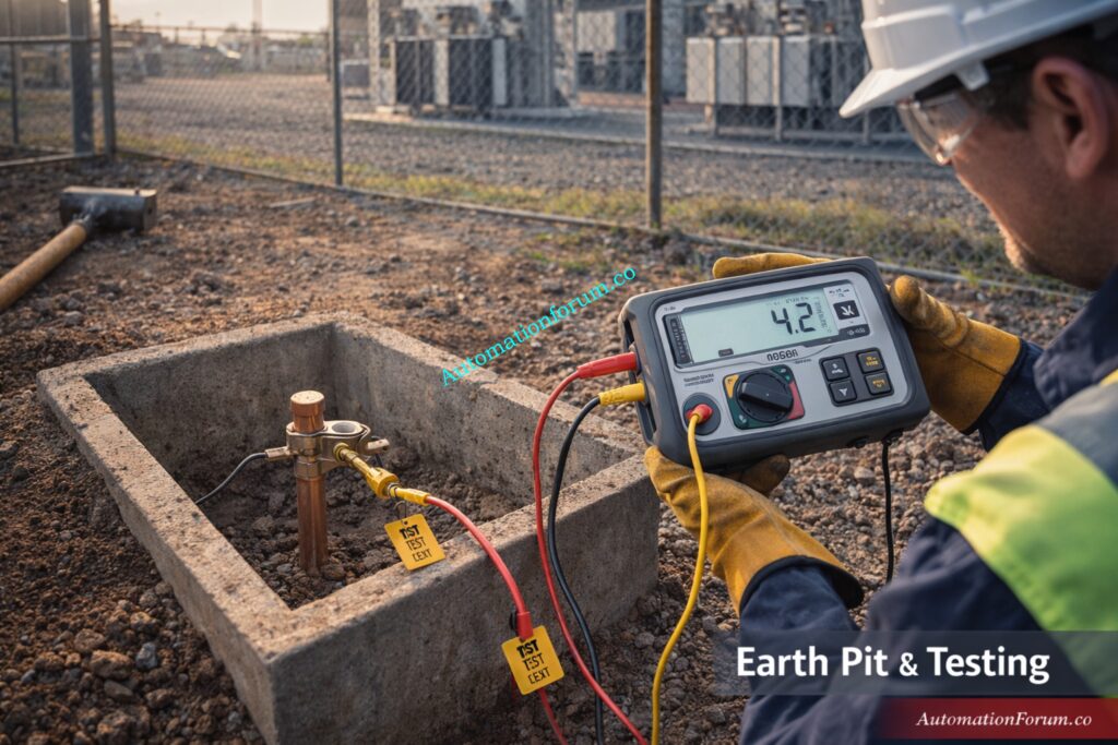
Understand Earth Pit Before Installation: What is an Earth Pit?
Frequently Asked Questions (FAQ) About Instrument Earth
What instrument is used to measure earthing?
A megger earth tester or an earth tester is a popular tool for measuring the resistance of a grounding system.
It helps make sure that the earthing path makes a low-resistance connection that safely gets rid of electrical noise and fault currents.
Troubleshoot 4-20 mA Loop Problems Step-by-Step: How to do troubleshooting of a 4-20mA loop?
What is the difference between plant earth and instrument earth?
People utilize plant earth to keep equipment secure and guard against electrical shocks by safely transferring fault currents to ground.
Instrument earth gives sensitive instrumentation signals a clean reference ground so that measurements stay accurate.
How to check instrument earthing?
Instrument earthing is checked by inspecting grounding connections, cable shield terminations, and instrument earth bus bars.
Engineers may also measure grounding continuity or resistance using an earth tester to confirm proper grounding performance.
Master Grounding and Bonding in Instrumentation Systems: Grounding and Bonding in Instrumentation and Control Systems
How to do instrument earthing?
Instrument earthing is done by connecting instrumentation equipment, cable shields, and control system chassis to a dedicated instrument earth bus bar.
This bus bar is then connected to the plant grounding grid through a low-resistance earthing conductor.
What is the difference between electrical earthing and instrument earthing?
Electrical earthing protects persons and equipment by safely sending fault currents to the ground when there are electrical problems.
Instrument earthing is meant to give instrumentation signals and control systems a reliable, noise-free reference point.
Refer the below link for Understanding the Difference Between Live Zero and Dead Zero in 4 to 20 mA Signals
How often should Instrument Earthing systems be inspected?
Instrument earthing systems should be inspected periodically as part of routine plant maintenance programs.
Regular inspections ensure grounding connections remain secure, corrosion-free, and effective in reducing electrical noise.
Are Instrument Earth and Safety Earth connected together?
Instrument Earth and Safety Earth are normally routed separately within industrial plants to prevent electrical interference.
However, they are typically bonded together at a single point in the main plant grounding grid.
What problems can occur if Instrument Earth is not installed properly?
Improper instrument earthing can cause fluctuating analog signals, unstable control loops, and communication errors in PLC or DCS systems.
It may also lead to false alarms, unexpected equipment trips, and unreliable process measurements.
Should cable shields be connected to Instrument Earth?
Yes, cable shields in instrumentation cables should normally be connected to the Instrument Earth system.
This allows electromagnetic noise captured by the shield to be safely drained to ground, protecting sensitive signal circuits.
Master Instrument Earthing Systems Now: Instrument Earthing Systems
Ensure Signal Integrity with Proper Instrument Earthing
Instrument Earth is a fundamental part of industrial automation systems. While Safety Earth protects people from electrical hazards, Instrument Earth protects the accuracy and reliability of measurement and control signals.
In modern plants where automation systems depend on precise data from hundreds of instruments, even small electrical disturbances can affect operations.
A well-designed instrument earthing system ensures stable signal reference, reduces electrical noise, and improves the overall reliability of PLC and DCS systems.
Instrumentation systems depend on precise and stable signals from field devices. A properly designed instrument earthing system provides a clean electrical reference, reduces electromagnetic interference, and ensures reliable communication between field instruments and control systems. By following proper grounding practices, using shielded cables, and maintaining dedicated instrument earth connections, industrial plants can significantly improve automation system performance and operational reliability.
Fix Panel Door Earth Bonding Correctly: Panel Door Earth Bonding Procedure: Ensuring Safety and Reliability
 provides a low-noise grounding reference for transmitters, PLC/DCS I/O and sensors. Practical earthing, shield termination & troubleshooting guide.)