- What is an Instrumentation Cable Tray?
- Common Mistakes in Instrumentation Cable Tray Installation
- Additional Considerations for EPC Instrumentation Cable Trays
- EPC Project Perspective: Why Avoiding These Mistakes Matters
- EPC Cable Tray Installation Checklist
- Frequently Asked Questions (FAQs) on Cable Tray Installation
- Downloadable EPC Instrumentation Cable Tray Installation Checklist
In instrumentation EPC (Engineering, Procurement, and Construction) projects, installing cable trays is very important for making sure that signals are sent reliably, that people are safe, and that systems work well for a long time. Unlike power cables, instrumentation cables generally transmit low-level signals, making them very sensitive to electromagnetic interference (EMI), mechanical stress, and incorrect routing techniques.
incorrect installation procedures in instrumentation cable trays can cause signal problems, make maintenance more frequent, create safety risks, and even waste a lot of time and money on projects. This document lists the most typical mistakes that EPC teams should not make while installing instrumentation cable trays to make sure the plant runs smoothly, is safe, and is in compliance.
What is an Instrumentation Cable Tray?
An instrumentation cable tray is a structured channel that holds and organizes signal, control, and communication cables in manufacturing facilities. Instrumentation trays are usually different from power tray systems in that they are:
- Dedicated and separated from power trays to keep signals from getting mixed up.
- Made with the right amount of shielding, spacing, and grounding in mind.
- Set up to allow for future growth without interfering with current operations.
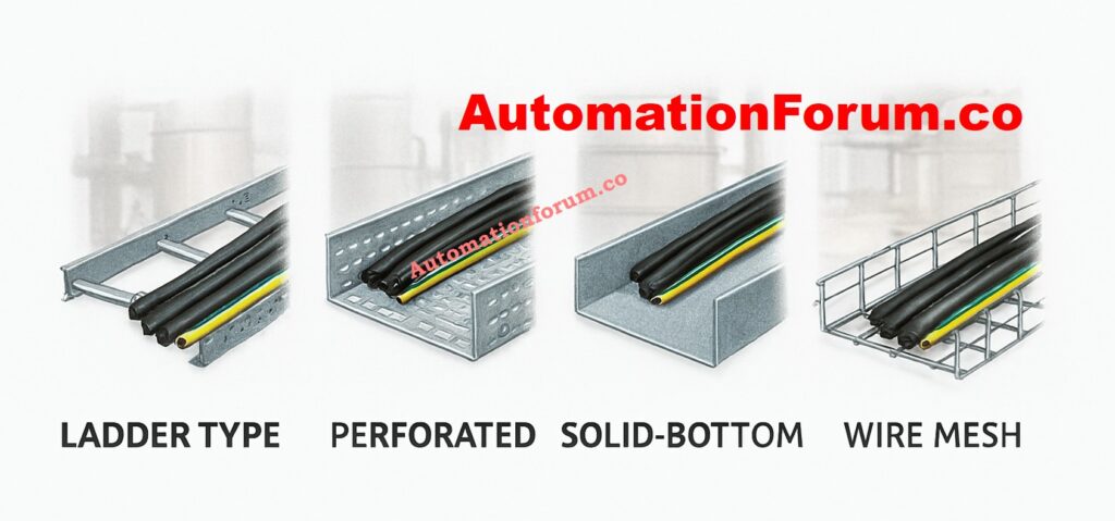
Common types of trays used in instrumentation projects include:
- Ladder trays: Ladder trays are useful for long cable runs that need good airflow.
- Perforated trays: Trays with holes in them are good for medium loads and some protection.
- Solid-bottom trays: Solid-bottom trays are good for protecting delicate signal cables from dust and moisture.
- Wire mesh trays: Wire mesh trays are great for flexible routing in data centers or control rooms.
Understand What is Cable Tray and How it is Used in Industrial Applications: What is Cable Tray and How it is used in Industrial applications?
Common Mistakes in Instrumentation Cable Tray Installation
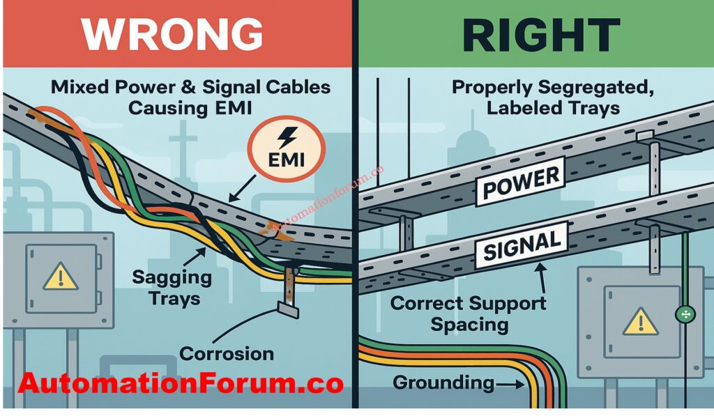
Mistake #1: Mixing Instrumentation and Power Cables in the Same Tray
One of the worst mistakes you can make on an EPC project is to run low-voltage instrumentation cables and high-voltage power cables in the same tray. This causes inductive coupling and EMI, which can make signals noisy, readings wrong, and systems unstable.
Mistake #2: Improper Tray Type Selection
Choosing the improper type of cable tray for the environment can cause problems with reliability over time. For example, employing trays with holes in them in regions where there is a lot of dust or humidity could cause corrosion and a loss of signal.
Best Practice:
- In places where things can corrode, including chemical industries and coastal refineries, use stainless steel trays.
- Use trays with solid bottoms for delicate instrumentation cables that are exposed to EMI.
- Choose ladder trays for hefty multi-core wires that need good air flow.
Mistake #3: Inadequate Planning and Poor Layout Design
Sometimes require complicated routing between process units, cable junction boxes (JBs), and Distributed Control System (DCS) panels. Not preparing ahead can lead to:
- Overcrowding
- Sharp bends that damage cable insulation
- Difficult future maintenance
Best Practice:
- Do thorough routing studies at the engineering phase.
- Follow the cable requirements for the minimal bending radius.
- Leave 30-40% of the space free for future growth.
View the Instrument Tray Layout Design and Planning Guide: Instrument Tray Layout
Mistake #4: Overloading Cable Trays
Overfilling trays with more cables than the design capacity can cause:
- Putting too many cables in trays that aren’t designed to hold them can cause:
- Mechanical stress on the jackets of cables
- Signal interference because the conductors are too close together
- Too much heat builds up over extended runs
Best Practice:
- Follow the rules for loading trays exactly.
- Make sure that the cables are evenly spaced across the width of the tray.
- Plan to group and tag cables to make maintenance easier.
Rrfer the below link to Explore the Complete Checklist for Intrinsically Safe Cables in ATEX Zones
Mistake #5: Incorrect Support Spacing and Fastening
If the tray supports aren’t right, the tray can sag, vibrate, and eventually fall apart. Even a little sagging in instrumentation trays can put stress on cables and cause grounding problems.
Best Practice:
- Install supports as per specifications (e.g., 1.5–2 meters spacing depending on tray type).
- Brackets, clamps, and bolts that don’t rust should be used.
- Don’t mix support materials, like an aluminum tray with steel supports without insulation pads.
Mistake #6: Ignoring Grounding and Bonding
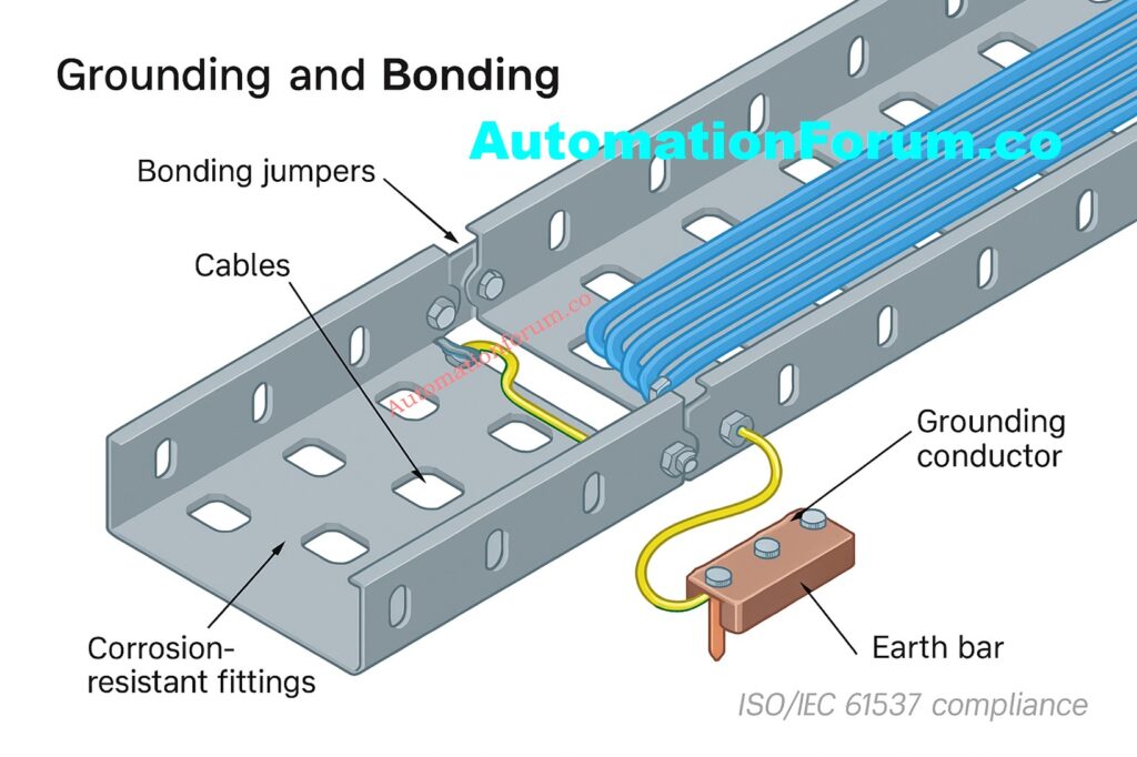
Ground loops and EMI can easily get into instrumentation cables. If cable trays aren’t properly grounded or bonded, they can send misleading signals, cause the system to trip, or even break the instrument.
Best Practice:
- Make sure that the tray length is always grounded.
- Use certified conductors to adequately bond all parts of the tray.
- Follow rules like NEC Article 392 and IEC 61537.
Mistake #7: Poor Segregation Between Analog and Digital Cables
If you put 4-20 mA analog signal cables and digital communication wires (such Fieldbus, Profibus, Ethernet, etc.) in the same tray, they could interfere with each other and make noise.
Best Practice:
- Keep separate trays or drawers for your analog and digital cords.
- Keep high-speed communication connections away from power circuits and variable frequency drives (VFDs).
- Follow the DCS vendor’s advice on how to separate cables.
Mistake #8: Using Low-Quality Materials and Hardware
Using cheap trays, joints, or fasteners makes it more likely that:
- Corrosion and tray collapse will happen in places where chemicals or the outdoors are present.
- Sharp edges can damage cables before they are needed.
- Regular maintenance and unexpected downtime.
Best Practice:
- Choose trays with the right anti-corrosion coating, such as hot-dip galvanized, epoxy, PVC-coated, or stainless steel.
- Use good grommets, cable ties, and fasteners.
- Before buying anything for an EPC project, undertake vendor audits.
Discover the Key Differences Between Intrinsically Safe (IS) and Non-IS Cables: Difference Between Intrinsically Safe (IS) and Non-IS Cables
Additional Considerations for EPC Instrumentation Cable Trays
Cable Tray Covers & Protection
- There is no mention of protection from dust, falling objects, rodents, UV rays, or bad weather.
- Outdoor instrumentation trays need covers (solid or vented) and other parts.
Fire Safety & Hazardous Area Considerations

- Trays that are rated for fire and meet NFPA/IEC flame spread regulations.
- Fire barriers or intumescent coatings are used in refineries and chemical industries.
- Installing cable trays in dangerous places (Zone 1/2, Class I Div 1/2) and following ATEX rules.
Thermal Expansion and Vibration Issues
- Long tray runs change size when the temperature changes.
- Need for flexible couplings, expansion joints, and vibration dampers, especially in places where machinery is rotating.
Cable Identification, Tagging, and Documentation
- How important it is to tag cables correctly, color code them, and keep records of how they were built for EPC turnover.
- This stops mistakes from happening during commissioning and later on when fixing things.
Seismic and Structural Load Considerations
- Cable tray supports must meet seismic design standards in areas where earthquakes are likely to happen or where heavy equipment is used.
Cable Tray Earthing vs. Cable Earthing
- There is a difference between bonding the tray and making sure that the cables are properly earthed or terminated at instruments or panels.
Drainage and Moisture Management
- Trays that are outside or in washdown areas should have drainage holes or be sloped so that water doesn’t pool.
Integration with Other Plant Systems
- Making sure that tray routing works with HVAC ducts, pipes, and access ways so that there are no problems throughout EPC implementation.
Inspection & Maintenance Strategy
- Regular checks for rust, sagging, loose bolts, or damage from rodents.
- Checklists for preventive maintenance can be useful.
Digital/Smart Cable Management

- Using BIM, 3D modeling, or digital twins to plan the configuration of cable trays.
- More and more, EPC projects employ software to find clashes, optimize cable routing, and keep track of assets.
Download the Instrumentation Cable Tray Installation Checklist and Inspection Procedure: Instrumentation Cable Tray Installation Checklist and Inspection Procedure
EPC Project Perspective: Why Avoiding These Mistakes Matters
In significant EPC instrumentation projects, avoiding these mistakes makes:
- Guarantee that the project is finished on schedule without having to do expensive rework.
- Minimal noise interference with reliable DCS/PLC performance.
- Following NEC, IEC, and project safety rules.
- Cut down on maintenance and cable replacement to lower the cost of the life cycle.
Installing cable trays properly isn’t just about holding wires up; it’s also about making sure signals are reliable, plants are safe, and systems stay intact over time.
Installing an instrumentation cable tray needs careful planning, engineering discipline, and following the rules. EPC teams can avoid typical problems such as incorrect segregation, overloading, poor grounding, and low-quality material consumption, ensuring:
- Instrumentation systems that are safe and dependable
- Following international rules
- Less time and money spent on maintenance and downtime
- Room for growth in the future
A properly installed cable tray provides the basis for dependable plant automation and control.
Review the Instrumentation Cable and Wiring Inspection Procedure and Checklist: Instrumentation Cable and Wiring Inspection Procedure: Essential checklist for Project Engineers
EPC Cable Tray Installation Checklist
| Stage | Checklist Item | Best Practice / Requirement |
| Design Phase | Tray Type Selection | Choose ladder, perforated, solid-bottom, or wire mesh based on load, environment, and signal sensitivity. |
| Segregation Plan | Separate trays for power, instrumentation, and communication cables; maintain spacing as per IEC/NEC. | |
| Spare Capacity | Design trays with 30-40% spare space for future expansion. | |
| Fire & Hazardous Area Compliance | Use fire-rated trays and ATEX/IECEx-approved materials in hazardous zones. | |
| Routing & Layout | Avoid sharp bends, congestion, and interference with HVAC/piping. | |
| Structural/Seismic Load | Ensure support design meets seismic/structural load requirements. | |
| Material Procurement | Tray Material | Select hot-dip galvanized, epoxy-coated, stainless steel, or FRP based on environment. |
| Covers & Accessories | Provide solid/vented covers, grommets, and protective linings for outdoor/harsh conditions. | |
| Hardware Quality | Use corrosion-resistant fasteners, clamps, and brackets. | |
| Installation Phase | Support Spacing | Install supports every 1.5–2 m (as per tray type and load). |
| Earthing & Bonding | Ensure continuous electrical bonding across tray sections; comply with IEC 61537/NEC 392. | |
| Expansion Joints | Provide expansion joints/flexible couplings in long runs or high-temperature zones. | |
| Cable Grouping & Tagging | Maintain orderly routing, bundle conductors, and label cables for identification. | |
| Moisture Management | Provide drainage holes/sloping in outdoor trays; prevent water pooling. | |
| Vibration Control | Use vibration isolation supports near rotating equipment. | |
| Inspection & Commissioning | Quality Check | Verify mechanical strength, alignment, grounding, and bonding. |
| Fill Factor | Ensure trays are not filled beyond 70% of capacity. | |
| Documentation | Update as-built drawings, tagging, and digital layout (BIM/3D). | |
| Safety Verification | Confirm compliance with NEC, IEC, and project specifications before handover. | |
| Operation & Maintenance | Routine Inspection | Check for corrosion, loose fasteners, sagging, damaged cables. |
| Preventive Maintenance | Clean trays, check bonding, replace damaged parts periodically. | |
| Digital Monitoring | (Optional, modern EPC) Use sensors or digital twin for cable health and tray integrity tracking. |
Read the Cable Gland Selection for Hazardous Area Installations – 2025 Guide: Cable Gland Selection for Hazardous Area Installations – Complete 2025 Guide
Frequently Asked Questions (FAQs) on Cable Tray Installation
What are the requirements for cable tray installation?
When installing cable trays, they must be strong, safe, and easy to get to. Use the right sort of tray, keep the support spacing between 1.5 and 2 meters, separate the power, control, and instrumentation cables, and make sure the grounding and bonding are done correctly. Leave 30 to 40 percent of the room free for future growth. For compliance and reliability, follow standards like IEC 61537 and NEC 392.
Learn How to Fix Common Cable Management Issues using Cable Tray Accessories: How to Fix Common Cable Management Issues using Cable Tray Accessories
What is the IEC standard for cable tray installation?
IEC 61537 is the principal IEC standard for cable management systems for ladder and cable trays. It lays out rules for mechanical load testing, electrical continuity, corrosion resistance, and how to install things. EPC projects generally use it along with IEC 60364 to make sure that all electrical installations are safe.
What are the 5 basic cable tray types?
- Ladder Tray: For heavy-duty industrial wires that need optimum air flow.
- Perforated Tray: For control and signal lines in general.
- Solid-Bottom Tray: For cables that need full protection.
- Wire Mesh Tray: For flexible routing in control rooms.
- Channel Tray: For short runs or small clusters of cables.
What are the disadvantages of cable trays?
Cable trays can rust in bad weather if they aren’t protected, need to be checked often, and can create EMI if they aren’t kept separate. They also don’t look very good and need to be properly grounded and covered in outdoor or chemical plants.
Use Our Cable Tray Fill Percentage Calculator for Accurate Sizing: Cable Tray Fill Percentage Calculator
What are the disadvantages of beating trays?
Vented trays, also known as perforated trays, can’t hold as much weight, let in dust and moisture, and may get weaker over time in corrosive situations. They aren’t great for heavy or high-voltage cables, but they perform well for light control or instrumentation circuits.
Why must conductors be installed in groups in a cable tray?
Grouping conductors keeps the route neat, makes sure the current is evenly distributed, and cuts down on electromagnetic interference. It also assists with identification, tagging, and future maintenance in EPC projects.
How many cables can fit in a cable tray?
The size of the tray, the thickness of the cable, and the fill factor all matter. Industry standards say that the tray should not be more than 70% full, keeping 30% of its capacity free for future growth or changes.
What is a major advantage of cable tray systems?
Cable trays are a versatile, safe, and cheap solution to organize cables. They make installation easier, make it easier to access for maintenance, support future modifications, and keep power and instrumentation wire separate and organized.
What is the ideal spare capacity to leave in cable trays?
It is best to leave 30–40% of the space free for future instrument extensions.
Downloadable Checklist for Installing EPC Instrumentation Cable Trays
Downloadable EPC Instrumentation Cable Tray Installation Checklist
We designed an EPC Cable Tray Installation Checklist that EPC engineers and site teams can use right away to make sure that installations are safe and up to code. This application makes it easy to keep track of the best practices for design, procurement, installation, inspection, and maintenance.
Calculate Proper Dimensions with the Cable Tray Size Calculation Guide for Engineers: Cable Tray Size Calculation for Project Engineers