How do valves work?
- Valves are used to control the flow and pressure inside a system or process.
- These are essential components of a piping system that moves fluids, gases, vapor, and other materials.
- There are many different types of valves, including pressure relief, control, gate, globe, plug, ball, butterfly, check, diaphragm, and many more.
- While some valves are self-operating, others can be operated manually, pneumatically, hydraulically, by an actuator, or both.
Function of Valves
- Flow that comes and goes
- Cut down or boost a flow
- Controlling the flow’s direction
- Controlling a process pressure or flow
- Release a specific pressure from a pipe system.
There are many different valve models, types, and designs with numerous industrial applications. All fulfil one or more of the aforementioned functions. The right valve must be selected for the purpose and made of the right material for the process liquid because valves are expensive products.
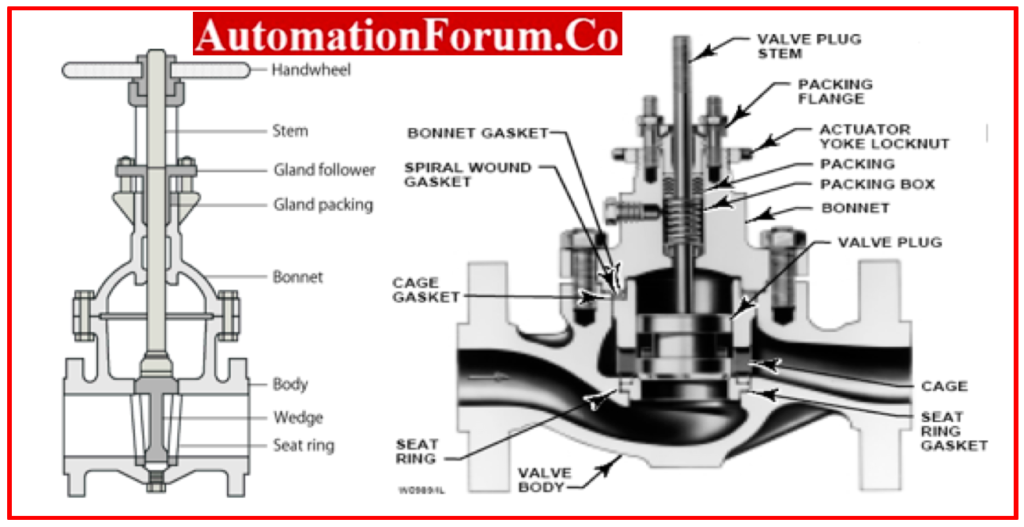
- The body, bonnet, trim (internal elements), actuator, and packing are the core components of all valves, regardless of type.
- The basic boundary of a pressure valve is the valve body, also referred to as the shell, in the valve assembly itacts as the primary Component
Valve Body
- The body of a valve is capable of withstanding pressure loads caused by associated piping. It is attached to the intake and outlet pipes by means of threaded, bolted, or welded connectors.

- The valve-body ends are constructed utilising a variety of end connections, such as threaded, flanged, butt or socket welded, etc., to connect the valve to the piping or equipment nozzle.
- Many different valve body types are cast or forged, and each part is constructed from a material suitable for that function.
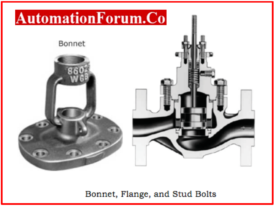
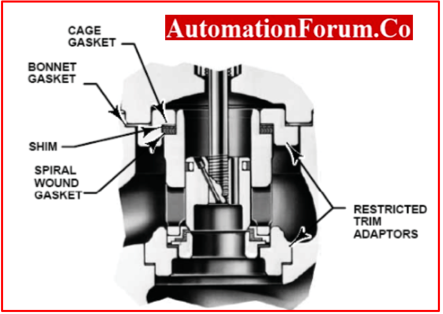
Valve Bonnet
- The bonnet, which serves as the opening’s cover, is a pressure valve’s second-most crucial barrier.
- The designs and types of bonnets are as varied as those of valve bodies
- The bonnet, or covering, for the valve body is either cast from the same material as the body or forged from it.
- Often, it is joined to the body via a threaded, bolted, or welded joint.
- The interior components of the valve, such as the stem, disc, and other sections, are assembled inside the body before the bonnet is put on to hold everything together.
- A pressure boundary is always considered to exist where the bonnet meets the body.
- This demonstrates that the pressure-maintenance components are the bolts or weld joint holding the bonnet to the body.
- Valve bonnets are necessary for the majority of valves, although they are problematic.
- In addition to potentially causing leaks, bonnets can make it more difficult to build valves, increase valve size, significantly raise the cost of a valve, and increase manufacturing complexity.
Valve trim
- The collective term for a valve’s changeable components is “trim”.
- A disc, seat, stem, and sleeves necessary to guide the stem are all included in the trim design.
- A valve’s performance is affected by the interface between the disc and seat and the relationship between the disc position and the seat
- Basic motions and flow control are made possible by the trim.
- The disc closely slid past the seat in rotational motion trim designs to cause a change in flow opening.
- In designs for linear motion trim, the disc is raised perpendicularly away from the seat, creating an annular aperture.
Disk and Seat Valve
Disk
- Depending on its position, the disc is the component that either permits, tampers, or prevents flow.
- The disc is referred to as a plug or a ball in the context of a plug or a ball valve.
- The third most significant major pressure boundary is the disc.
- The disc is a pressure related component because when the valve is closed, the entire system pressure is applied across it.
- To achieve good wear qualities, discs are often forged and in some designs, hard surfaced.
- The design of their discs is how most valves get their names.
Seat
- The seat or seal rings offer the disk’s seating surface.
- A valve may have one, two, or more seats.
- A globe or swing-check valve typically only has one seat, which combines the disc in a seal to stop the flow.
- A gate valve has two seats, one on each side of the valve: upstream and downstream.
- To produce a seal and stop the flow, two seating surfaces on the gate valve disc make contact with the valve seats.
- To strengthen the seal rings’ wear resistance, the contact surface of the seal ring is usually hard-faced by welding and then machining.
- The seating region needs to have a smooth surface finish in order to guarantee adequate sealing when the valve is closed.
- As the body has enough wall thickness to resist design pressure without depending on the thickness of the seal rings, seal rings are typically not thought of as pressure boundary sections.
Valve Stem
- The valve stem is in charge of ensuring that the disc is positioned correctly and giving the disc, plug, or ball the movement they require to open or close the valve.
- Although plug, ball, and butterfly valves require the disc to be spun in order to open or close the valve, gate or globe valves require the disc to move linearly.
- Often, stems are forged and attached to the disc using threaded or other methods.
- A fine surface finish on the stem is required to avoid leaking in the vicinity of the seal.
There are five different kinds of valve stems.
Rising stem with outside Screw & Yoke
- The portion of the stem that is inside the valve is smooth, while the exterior of the stem is threaded.
- The stem packing separates the stem threads from the flow media.
- There are two different versions of these designs: the first attaches the handwheel to the stem so that they both rise at the same time, and the second threaded sleeve makes the stem rise with the help of handwheel.
Rising Stem with an Inside Screw
- The valve stem’s threaded portion is located inside the body of the valve, and the smooth portion of the stem is exposed to the environment outside.
- In this instance, the flow medium is in touch with the stem threads.
- The handwheel and stem combined rise when rotated to open the valve.
Non-Rising Stem with Inside Screw
- The stem’s threaded portion, which is located inside the valve, does not raise.
- If the stem is rotated, the valve disc moves along it like a nut.
- Stem threads are impacted because they are exposed to the flow media.
- This model is utilized in situations when there isn’t enough room for linear movement and the flow medium doesn’t lead to stem material erosion, corrosion, or abrasion.
Sliding Stem
- The stem of this valve does not turn or rotate.
- To open or close the valve, it slides in and out.
- Hand-operated lever rapid opening valves employ this concept.
- Moreover, it is utilized in control valves that hydraulic or pneumatic cylinders operate.
Rotary Stem
- This is a frequently employed design for Butterfly, Ball, and Plug valves.
- The stem may be rotated a quarter turn to open or close the valve.
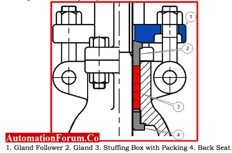
Valve Stem Packing
A gasket is required between the stem and the bonnet. This is referred to as a packing, and it is equipped with things like the following:
- A gland follower, also known as a stuffing box sleeve, compresses the packing by a gland.
- A type of bushing called a gland compressed the filling into the box.
- A compartment in which the packing is crushed is called a stuffing box.
- Packaging, which can be made from a variety of materials including Teflon®, elastomeric material, fibrous material, etc.
- A backseat is a place to sit inside the hood.
When the valve is fully open, it acts as a seal between the stem and bonnet and stops system pressure from building up against the valve.
Gate and globe valves frequently use back seats.
Valve Yoke and Yoke
Yoke
- A yoke connects the actuation mechanism to the valve body or bonnet.
- The top of the yoke, which is holding a yoke nut, stem nut, or yoke bushing, is where the valve stem passes through.
- The structural integrity of a yoke must be strong enough to withstand the forces, moments, and torque produced by the actuator.
Yoke Nut
- In order for the stem to pass through a yoke, an internally threaded nut known as a yoke nut must be placed.
- For instance, twisting a gate valve’s yoke nut will move the stem either upward or downward.
- Globe valves has fixed nut which rotates the stem
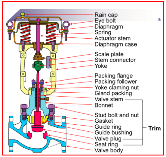
Actuator
- Typically, hand-operated valves include a hand-wheel attached to the stem or yoke nut that may be turned either clockwise or anticlockwise to close or open a valve.
- A lever is used to actuate hand-operated quarter-turn valves such a ball, plug, or butterfly.
- In some situations, operating the valve manually using a handwheel or lever is not feasible or desirable.
Among these applications are
- Hefty valves that need to be turned while under high hydrostatic pressure
- They need to be operated from a distance when using valves.
- When a system’s design conditions are not met, such as when the valve must be opened, closed, throttled, or manually controlled
Actuator with valves
A device that generates linear and rotary motion of a power source while being controlled by a control source is referred to as an actuator.
- A valve can be fully opened or closed using simple actuators.
- A positioning signal is sent to actuators that control or regulate valves so they can move to any intermediate position.
There are a wide variety of actuator types, but the following are some of the most popular valve actuators:
- Actuator gears
- Actuators for electric motors
- Air-powered actuators
- Actuators with hydraulics
- Actuators with solenoids
Valve Classification
Based on mechanical motion, the following are some of the most used valve classifications:
Valves for linear motion
The valves that allow, halt, or throttle the flow by moving the closure member in a straight line, such as gate, globe, diaphragm, pinch, and lift Check Valves.
Valves with rotary motion
Rotating motion valves, such as butterfly, ball, plug, eccentric-, and swing check valves, are those in which the valve-closure component travels in an angular or circular direction.
Valve Quarter Turns
With some rotational motion valves, turning the stem from fully closed to fully open or vice versa requires around a quarter revolution (0 to 90°).
Frequently Asked Questions:
What is meant Excess Flow Valve?
A spring-loaded check valve known as an excess flow valve will only close when the passage of liquid or vapor through it generates enough flow or force to overcome the force of the spring holding it open.
Depending on the application, these valves come in a variety of sizes and flow rates or vapor can flow via excess flow valves in either direction.
Only one direction is controlled for this flow. The valve will automatically close if the flow rate in that direction is higher than the desired point.
Which Valve can be used for over pressure protection?
A piston valve serves as the overpressure safeguard for pressure monitoring equipment. The outlet position is maintained by a helical spring until the pressure on the piston surpasses the spring’s back pressure, closing the valve.