
- Calculate Junction Box Load, Terminal Requirement and Enclosure Size Accurately
- What is a Junction Box Load Calculator?
- Why Engineers Need a Junction Box Load Calculator
- Engineering Theory of Junction Box Load Calculation
- Junction Box Load Calculator Inputs Explained
- Junction Box Load Calculator Outputs Explained
- Engineering Formulas Used in the Junction Box Load Calculator
- How to Use the Junction Box Load Calculator
- Industrial Applications of the Junction Box Load Calculator
- Junction Box Design Considerations
- Hazardous Area Design Considerations for Junction Boxes
- Applicable Engineering Standards for Junction Box Design
- Junction Box Installation Best Practices
- Frequently Asked Questions About the Junction Box Load Calculator
- Conclusion: Key Takeaways from the Junction Box Load Calculator
Junction Box Load Calculator
Size instrumentation junction boxes for field devices in process automation — power budget, terminal count, IS parameters, and enclosure sizing per IEC 60079, ISA-RP12, and NEC standards.
| # | Tag / Description | Device Type | Wiring | Qty | mA / Device | Terminals / Device | Ex i? | Remove |
|---|
Calculate Junction Box Load, Terminal Requirement and Enclosure Size Accurately
One of the most significant components of an industrial instrumentation system is a junction box. It may look like a basic housing for terminating cables, but a well-designed junction box is essential to provide dependable signal transmission, safe power distribution, and organized field wiring. The wrong size junction box can mean crowded terminals, inadequate power capacity, difficult maintenance and even problems with hazardous area compliance.
Challenges of Manual Junction Box Load Calculation
Instrumentation engineers during engineering and detailed design phase need to determine the number of field devices to be connected to a junction box, total current requirement, number of terminal blocks required and select an appropriate size of enclosure with adequate spare capacity for future expansion. These calculations become even more crucial in hazardous locations where Intrinsic Safety, Flameproof or Increased Safety criteria must be taken into account.
How the Junction Box Load Calculator Simplifies Instrumentation Design
The Junction Box Load Calculator simplifies this engineering process by providing a single tool that combines power calculations, terminal sizing, enclosure selection, hazardous area assessment and engineering recommendations. Instead than having to do many manual calculations with spreadsheets, engineers may rapidly examine various design choices and check to see whether a suggested layout of a junction box fits project criteria.
Who Should Use This Junction Box Load Calculator
This calculator is useful for instrumentation engineers, EPC contractors, commissioning engineers, maintenance personnel, project engineers and design consultants working in oil & gas, petrochemical, power generation, pharmaceutical, mining, food processing, water treatment and manufacturing industries.
Refer the below link for the Marshalling Panel vs Junction Box vs System Cabinet: Complete Guide
What is a Junction Box Load Calculator?

A Junction Box Load Calculator is an engineering tool used to calculate the electrical and physical requirements of an instrumentation junction box before installation.
The calculator will calculate a number of essential design factors like total current consumption, power demand, available power margin, terminal block quantity, spare terminals, enclosure size, cable entry requirements and hazardous area compatibility.
Rather than making these estimates by hand, engineers may enter their project data into the calculator and get design advice based on established engineering practice, instantly.
The calculator helps answer questions such as:
- Is the power supply sufficient for all connected instruments?
- How many terminal blocks are required?
- How many spare terminals should be provided?
- Which enclosure size should be selected?
- Is the junction box suitable for the selected hazardous area?
- Are additional cable entries required for future expansion?
- Does the design include adequate engineering margins?
These answers assist engineers to create robust solutions with less engineering time and less costly field adjustments.
Prevent Expensive Installation Mistakes Using Proven EPC Best Practices: 25-Point Instrumentation Junction Box (JB) Wiring and Termination Checklist for EPC Engineers
Why Engineers Need a Junction Box Load Calculator
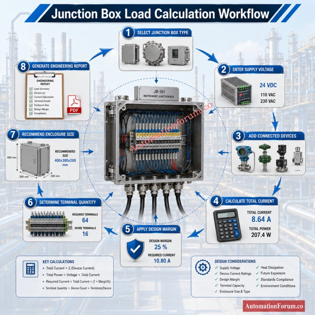
These answers assist engineers to create robust solutions with less engineering time and less costly field adjustments.
This calculator helps engineers:
- Total current consumption of the linked devices.
- Check available power supply capacity.
- Calculate power necessary with engineering safety factor
- Terminal block needs calculation.
- Provide spare terminals for future growth.
- Suggest size of enclosure.
- Estimate cable entry requirements
- Check hazardous area compatibility.
- Enhance engineering documentation.
- Fewer commissioning problems.
- Support design reviews.
- Standardise the selection of junction boxes in projects.
- Engineering Theory of Junction Box Loading Calculation
Challenge Your Instrumentation Knowledge With Advanced Engineering Questions: Advanced 25-MCQ on Instrumentation Junction Box Schedule Engineering Drawing
Engineering Theory of Junction Box Load Calculation
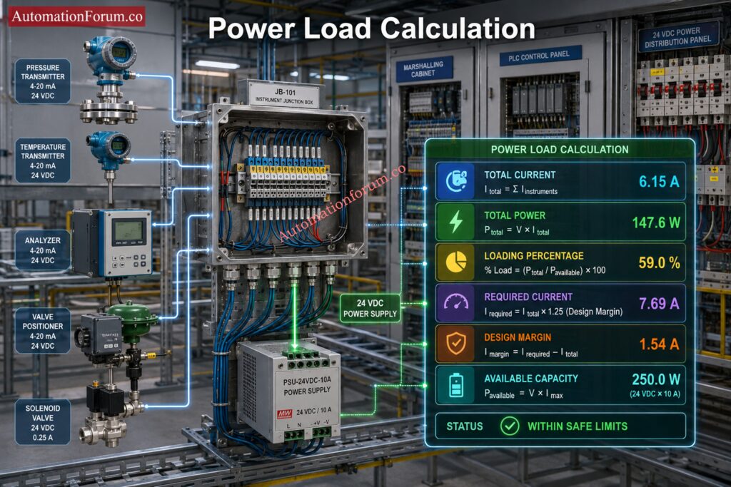
Understanding Instrumentation Junction Box Power Consumption
Every field instrument connected to a junction box consumes electrical current. Two wire transmitters generally operate from a twenty four volt DC loop and consume only a few milliamperes, while devices such as solenoid valves, analyzers, and positioners may require significantly higher current.
How Total Load Current Is Calculated
The total load current is calculated by adding the current consumption of every connected device.
Total Current = Sum of Device Current × Quantity
The calculator then calculates the overall power need, knowing the total current.
Power = Voltage × Current
Engineers never size the power supply exactly to the calculated load for reliable operation. A design buffer is included to handle future instrumentation, manufacturing tolerances, cable losses and unforeseen operational situations.
The calculator will also calculate the total number of terminals needed.
How Terminal Requirements Are Determined
The number of termination points needed for each instrument depends on the wiring layout for that instrument. Shield termination and grounding terminals are provided as well. Finally spare terminals are added in accordance with the desired spare %.
Recommended enclosure size is based on total number of terminals, cable entrances and available installation space.
Design More Efficient Systems With Professional Engineering Standards: Instrument Junction Box (JB) schedule
Junction Box Load Calculator Inputs Explained
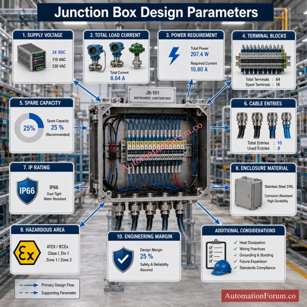
| Input | Engineering Purpose |
| Junction Box Type | Selects Standard, Ex d, Ex e, Ex i, or Fieldbus junction box |
| Hazardous Area Classification | Defines installation environment and certification requirements |
| Supply Voltage | Operating voltage, typically twenty four volt DC |
| Supply Capacity | Maximum current available from the power supply |
| IP Rating | Determines environmental protection against dust and water |
| Enclosure Material | Stainless steel, carbon steel, aluminum, or polycarbonate |
| Spare Terminal Percentage | Additional terminals reserved for future expansion |
| Design Margin | Extra current allowance for reliable operation |
| Device Type | Selects transmitter, analyzer, solenoid valve, control valve, RTD, or other field device |
| Device Quantity | Number of identical devices connected |
| Current per Device | Current consumed by each instrument |
| Terminals per Device | Number of wiring terminals required |
| Intrinsic Safety Selection | Identifies devices requiring Intrinsic Safety protection |
Understand Essential Industrial Concepts Every Instrument Engineer Needs: What is a Junction box, and its applications?
Junction Box Load Calculator Outputs Explained

The calculator automatically generates several engineering results.
Total Load Current: Displays the total current required by all the connected field devices..
Total Power: Computes the total electrical power utilized by the junction box.
Required Current with Design Margin: Incorporates the chosen engineering safety margin to guarantee reliable operation and future expansion.
Power Supply Headroom: Indicates the available current once the associated load is subtracted.
Loading Percentage: This is the load on the power supply.
Terminal Requirement: Calculates active terminals, shield terminals, spare terminals, and total terminal count.
Recommended Terminal Strip: Suggests the nearest standard terminal strip size.
Recommended Enclosure Size: Provides enclosure dimensions suitable for the calculated terminal count.
Cable Entry Estimate: Calculates the minimum number of cable glands required.
Hazardous Area Recommendation: Recommends suitable certification according to the selected hazardous area classification.
Learn Smart Layout Practices That Improve Plant Installation Quality: What is Instrument location layout and Junction box location layout?
Engineering Formulas Used in the Junction Box Load Calculator
Total Load Current
Total Current = Device Current × Quantity
Total Power
Power = Voltage × Current
Required Current
Required Current = Total Current × Design Margin
Loading Percentage
Loading Percentage = Required Current ÷ Supply Capacity × 100
Spare Terminals
Spare Terminals = Active Terminals × Spare Percentage
Total Terminals
Total Terminals = Active Terminals + Shield Terminals + Spare Terminals
These calculations offer engineers with a rapid means of evaluating junction box capacity with suitable engineering margins.
Solve Critical Instrument Faults Before They Cause Plant Shutdowns: Why Is My Pressure Transmitter Showing 22 mA? Complete Troubleshooting Guide for Instrument Engineers
How to Use the Junction Box Load Calculator
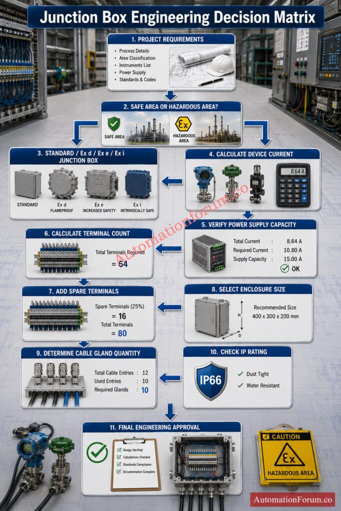
The calculator has been designed so that engineers can complete an entire junction box evaluation using a logical sequence.
Step 1 Select the Junction Box Type
Select the junction box type according to the installation requirements.
Choose Standard, Increased Safety, Flameproof, Intrinsically Safe or Fieldbus as per project specification.
Step 2 Select the Hazardous Area Classification
Choose the hazardous area classification.
This determines the required certification and affects the engineering advice produced by the calculator.
Step 3 Enter the Power Supply Voltage
Enter the power supply voltage.
Most projects use twenty four volt DC.
Always verify the actual project specification before entering the value.
Step 4 Enter the Power Supply Capacity
Entered Power Supply Capacity Available.
The calculator evaluates this value against the load computed to check if capacity is enough.
Step 5 Select the Enclosure Material and IP Rating
Choose enclosure material and environmental protection class.
Select materials appropriate for the installation environment and the intended service conditions.
Strengthen Your Automation Documentation With Industry-Proven Standards: PLC System Documentation Guide: Essential Records for Industrial Automation
Step 6 Configure Spare Terminals and Design Margin
Specify the spare terminal % and power design margin
These values indicate the future potential for expansion.
Step 7 Add Connected Field Devices
Add every connected field device.
For each instrument enter:
- Device type
- Quantity
- Current consumption
- Required terminals
- Intrinsic Safety requirement if applicable
Step 8 Review the Calculation Results
Run the calculation.
The calculator immediately generates:
- Total current
- Total power
- Loading percentage
- Remaining capacity
- Terminal requirement
- Recommended terminal strip
- Recommended enclosure
- Cable entry estimate
- Hazardous area recommendations
- Design recommendations
Instead of manually checking multiple spreadsheets, engineers receive a complete design assessment in one report that can be reviewed before procurement or construction begins.
Create Accurate Engineering Documents Faster With Professional Methods: Instrument Index Generator for EPC Instrumentation Projects
Industrial Applications of the Junction Box Load Calculator
The calculator is widely used during front end engineering design, detailed engineering, commissioning, plant expansion, and maintenance projects.
Typical applications include:
- Oil and gas production facilities
- Refineries
- Petrochemical plants
- Chemical manufacturing
- Power plants
- Water treatment facilities
- Pharmaceutical plants
- Food processing industries
- Mining operations
- Steel manufacturing
- Marine installations
- Renewable energy projects
- Industrial utility systems
Improve Junction Box Design Using Proven Industrial Engineering Techniques: JB Grouping in Industrial Automation and Instrumentation
Junction Box Design Considerations
When designing an instrumentation junction box, engineers should consider several important factors.
- The power supply capacity should always exceed the anticipated connected load. Additional spare connections and enclosure space should be provided to allow for future expansion.
- Cables should be routed to minimize signal interference and facilitate maintenance. Proper termination of shielded instrumentation cables is critical to prevent electrical noise.
- The material of the enclosure should be compatible with the ambient conditions. The stainless steel gives great corrosion resistance. Polycarbonate allows lightweight construction for less demanding situations.
- The IP rating selected should be acceptable for installation situations outdoor or indoor.
- Hazardous areas demand certified enclosures, cable glands and accessories to meet the relevant standards.
Perform Precise Calibration Calculations With Greater Engineering Confidence: Transmitter Calibration Calculator: How to Calculate Span, LRV, URV, and 4 to 20 mA
Hazardous Area Design Considerations for Junction Boxes
Hazardous area installations require additional engineering attention because incorrect equipment selection may introduce ignition sources.
Standard industrial junction boxes are generally acceptable where no explosive atmosphere exists.
Even in safe areas, engineers should provide adequate environmental protection and spare capacity.
Zone 2 Installations
- Zone 2 locations contain explosive atmospheres only under abnormal operating conditions.
- Equipment used in these areas must satisfy the applicable certification requirements.
- The power supply capacity should always exceed the anticipated connected load.
Zone 1 Installations
- Zone 1 areas require certified equipment capable of operating safely where explosive gas may be present during normal plant operation.
- Every component including the enclosure, cable glands, stopping plugs, and accessories should comply with project specifications.
Intrinsically Safe Circuits
- Intrinsic Safety limits the available electrical energy so that ignition cannot occur.
- When Intrinsically Safe circuits are installed inside a junction box, they should remain separated from non Intrinsically Safe circuits according to project standards.
- Proper identification and segregation improve both safety and maintenance.
Flameproof Enclosures
- Flameproof enclosures are designed to contain any internal explosion without allowing ignition to spread to the surrounding atmosphere.
Applicable Engineering Standards for Junction Box Design
A well designed junction box should comply with internationally recognized engineering standards.
The calculator supports engineering practices consistent with these standards.
| Standard | Engineering Significance |
| IEC 60079 | Explosive atmosphere equipment requirements |
| IEC 60079 11 | Intrinsic Safety design principles |
| IEC 60079 14 | Installation requirements for hazardous locations |
| IEC 60529 | Degree of protection provided by enclosures |
| ISA 5.1 | Instrument identification and documentation |
| ISA RP12.6 | Hazardous location wiring practices |
| NEMA 250 | Industrial enclosure performance requirements |
| NEC Article 314 | Junction box installation practices |
| IEC 61158 | Foundation Fieldbus applications where applicable |
Compliance with these standards improves safety, reliability, maintainability, and project acceptance.
Develop Reliable PLC Alarm Strategies Following Industrial Best Practices: PLC Alarm and Trip Documentation Procedure – EPC PLC Automation Engineer Guide
Junction Box Installation Best Practices

Following good installation practices is equally as important as selecting the correct junction box.
- Before installation, installation engineers and personnel should always check that the enclosure has not been damaged during shipping.
- Cable glands should be tightened to the manufacturer’s recommendations to retain the required environmental protection rating.
- All unused cable entrances are to be sealed with approved stopping plugs.
- Cable shields should be terminated according to the project grounding philosophy.
- When wiring is complete, all terminals should be checked for correct tightening torque.
- Check the gasket on the junction box enclosure door to make sure moisture cannot get in.
- Before powering the system, continuity, insulation resistance and loop testing should be accomplished.
- Any field modifications made during installation should be reflected in the appropriate documentation.
Optimize Calibration Planning Using Smart Risk-Based Maintenance Methods: Calibration Interval Risk Calculator for Industrial Instrument Calibration Planning
Frequently Asked Questions About the Junction Box Load Calculator
How to calculate the size of a junction box?
Determine the number of terminals, cable entrances and spare capacity and select an enclosure that provides adequate internal space for wiring and future expansion. Environmental circumstances, access for maintenance and hazardous area criteria should be considered before to deciding on the ultimate size.
How to calculate load for a sub panel?
Add up the power or current of all connected electrical loads, then apply the appropriate demand factors and design margin The computed load shall not exceed the sub panel and protective devices’ rated capacity.
What is the NEC 220.82 load calculation?
NEC 220.82 is an optional method for determining dwelling unit electrical loads by applying demand factors to connected loads. Knowing what size service or feeder is necessary per the National Electrical Code helps.
What is the purpose of an instrumentation junction box?
An instrumentation junction box provides a safe termination point for field instrument wiring and also provides a means of routing and safeguarding the wiring prior to sending the signals to the control system. This makes it easier to manage, maintain and repair the cables.
Download Ready-to-Use Templates That Simplify Every Engineering Project: Downloadable Engineering Documentation Instrumentation and Control Templates
Why is junction box sizing important?
The size of the junction box will be such that it will accommodate for the connectors, cable glands, internal wiring and any future extension. It also increases maintenance access and avoids the crowding that affects reliability.
Why should spare terminals be provided?
Spare terminals allow the addition of future instruments or adjustments without replacing the complete junction box. They lower maintenance costs and allow for flexibility in plant growth.
How is total load current calculated?
The total load current is the sum of the current consumption of each connected field device multiplied by its amount. This figure is used to calculate power requirements and to check that the power source has adequate capacity.
Why is a design margin included?
A design margin provides extra capacity for future expansion, cable losses, and unforeseen operational conditions. It increases the long term reliability and prevents overloading of the power supply.
Which voltage is commonly used for instrumentation systems?
Most of the industrial instrumentation systems employ twenty four volt DC power supply. This is because it provides reliable functioning of transmitters, analyzers and other field equipment. Supply voltages may be varied for some specialty applications.
What happens if the power supply is overloaded?
Excessive power loading can result in voltage drops, irregular operation of instruments, loss of communications and abrupt shutdowns. The load should not be beyond the rated capacity of the supply.
What is an IP rating?
IP rating basically tells how well the enclosure protects against entrance of dust and water. The right IP rating can help assure reliable operation of the product in its specified installation environment.
When should stainless steel enclosures be selected?
Stainless steel enclosures should be chosen for corrosive, offshore, marine and chemical processing situations where excellent corrosion resistance is required. They also have great resilience outside in extreme situations.
Why is hazardous area classification important?
The hazardous area categorization defines the type of certified junction box and electrical equipment needed for safe installation. Correct classification prevents fire hazards and guarantees compliance with the applicable safety standards.
Conclusion: Key Takeaways from the Junction Box Load Calculator
A properly constructed junction box will make an instrumentation system safer, more reliable and easier to maintain . The Junction Box Load Calculator provides engineers with a systematic engineering approach to calculating power requirements, terminal amounts, enclosure size, cable entry and hazardous area compatibility. The program automates these calculations, therefore reducing engineering labor, minimizing design errors, supporting compliance with international standards and ensuring instrumentation systems stay dependable throughout their operating life.
Whether you are constructing a new process plant, renovating an existing facility or producing engineering documentation for an EPC project, this calculator gives useful engineering recommendations for correct design choices and efficient project execution.
Refer the below link for the Types of Engineering Drawings and Documents used in Instrumentation
