- JB Grouping in Process Industry Instrumentation Systems
- What Is JB Grouping in Instrumentation Engineering?
- Why JB Grouping Is Critical in Industrial Automation Projects
- Key Design Criteria for JB Grouping in Instrumentation Engineering
- Intrinsically Safe (IS) and Non-Intrinsically Safe (NIS) JB Grouping Philosophy
- Role of 3D Engineering Tools in Junction Box Grouping Design
- JB Grouping Checklist Before Finalizing Instrumentation Design
- Documents Required for Accurate JB Grouping in Instrumentation Projects
- Practical JB Grouping Example from a Chemical Process Plant
- Common JB Grouping Mistakes Observed During Site Execution and Commissioning
- Best Practices for Effective JB Grouping in Industrial Automation Projects
- Commissioning Engineer’s Pro Tip on Junction Box Grouping
- Why Proper JB Grouping Is Essential for Safe and Reliable Industrial Automation
- Frequently Asked Questions (FAQ) on Junction Box (JB) in Instrumentation and Electrical Systems
JB Grouping in Process Industry Instrumentation Systems
JB grouping is one of the most important yet frequently overlooked engineering tasks in projects involving industrial automation and instrumentation. If the project is in oil and gas, chemical plants, power generation, pharmaceuticals, cement, steel, or water treatment facilities, the quality of the installation, the speed of commissioning, the safety of the plant, and the efficiency of long-term maintenance all depend on how well the junction boxes are grouped.
JB grouping may sound very technical, but it’s really just about having wiring make sense, making maintenance easy, and making commissioning go well. If you don’t arrange your JB grouping well, it might cause signal noise, grounding problems, frequent loop check failures, extra effort on site, and longer startup delays. A well-designed JB grouping philosophy, on the other hand, makes sure that the wiring is clean, the signals are reliable, the troubleshooting is faster, and all project and safety criteria are met.
This article is a full, useful, and SEO-friendly reference to JB grouping. It covers what it is, why it’s important, how to design it, safety issues, signal separation, using 3D tools, best practices, frequent mistakes, and examples from real process plants.
Test Your Skills: 25 JB MCQs: Advanced 25-MCQ on Instrumentation Junction Box Schedule Engineering Drawing
What Is JB Grouping in Instrumentation Engineering?
Definition of Junction Box (JB) Grouping in Industrial Automation
JB grouping is the process of putting field instruments, actuators, analyzers, and electrical signals into the right junction boxes (JBs) based on engineering logic, safety categorization, signal type, and physical location.
JB grouping defines:
- Which field instruments terminate in which junction box
- How many signals are assigned to one JB
- How signals are segregated inside the JB
- How cables are routed from field instruments to control systems
The basic goal is to have structured wiring, short cables, less interference, quick troubleshooting, and safe functioning.
Complete JB Schedule Explained Simply: Instrument Junction Box (JB) schedule
Why JB Grouping Is Critical in Industrial Automation Projects
Impact of JB Grouping on Instrument Installation and Cable Routing Efficiency
When you install, putting the JBs together correctly makes it easier to route cables and keeps trays from getting too full. When instruments from the same area or piece of equipment are logically grouped together, it is easier and faster to draw cables, and there is less danger of mis-termination.
Role of JB Grouping in Faster Commissioning and Loop Checking
JB grouping is very important for commissioning. Engineers can do the following using well-grouped JBs:
- Find loops fast
- Follow signals effortlessly
- Find problems without having to open more than one JB.
Many commissioning delays happen not because the instruments are broken, but because the JB groups are set up wrong and the terminals are planned wrong.
Effect of JB Grouping on Signal Integrity and Control System Reliability
- Signal fluctuation
- Unstable readings
- False alarms
Long-term signal stability and accurate process control depend on correct JB grouping.
JB Grouping Requirements for Safety, Hazardous Areas, and Code Compliance
JB grouping must precisely follow:
- Hazardous area classification
- Intrinsic safety requirements
- Voltage separation rules
Not being able to organize JB correctly can cause safety violations, inspections to be turned down, and big operational concerns.
Must-Read 25-Point JB Wiring Checklist: 25-Point Instrumentation Junction Box (JB) Wiring and Termination Checklist for EPC Engineers
Key Design Criteria for JB Grouping in Instrumentation Engineering
Instrument Location and Area-Based Junction Box Grouping
Knowing where the instruments are physically is one of the first steps in JB grouping. It would be best if you put instruments that are in the same process unit, skid, or equipment area into junction boxes that are close to each other.
This method:
- Minimizes cable length
- Reduces voltage drop and signal loss
- Simplifies maintenance access
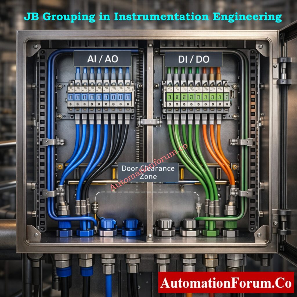
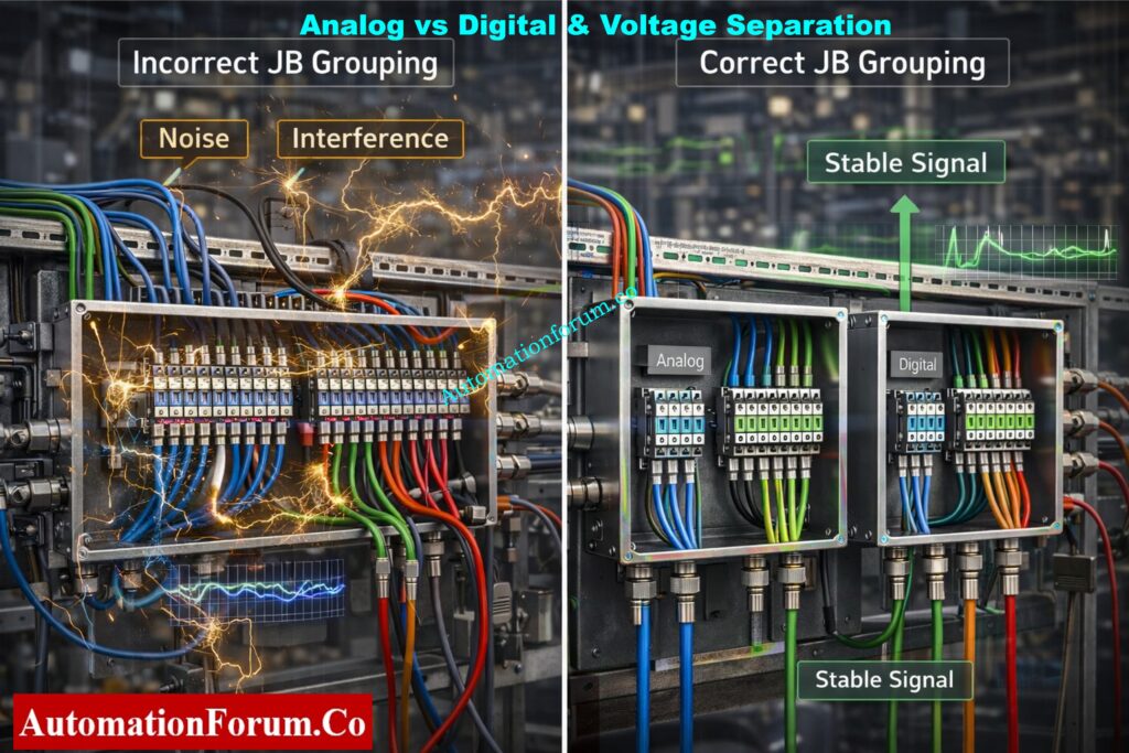
Separation of Analog and Digital Signals in Junction Box Grouping
Grouping of junction boxes to separate analog and digital signals
One of the most fundamental rules for JB grouping in instrumentation is to put analog and digital signals in separate junction boxes.
AI and AO are examples of analog signals. They are low-level signals that can be affected by electrical noise. Digital signals like DI and DO require switching operations that might cause interference.
Keeping analog and digital signals in different JBs:
- Prevents signal interference
- Improves control loop stability
- Keeps wiring clean and organized
- Simplifies troubleshooting
In a lot of EPC projects, DI and DO signals are also put in distinct JBs, based on the client’s and project’s standards. This may add more JBs, but it makes the system much clearer and more reliable.
Voltage Level Separation in JB Grouping (ELV, LV, and IS Circuits)
JB grouping must always take voltage levels into account. Some common voltage ranges are:
- Extra Low Voltage (ELV)
- Low Voltage (LV)
- Intrinsically Safe (IS) circuits
If you don’t separate multiple voltage levels in the same JB, you could have insulation problems, noise problems, and safety problems.
Junction Box Explained for Beginners: What is a Junction box, and its applications?
Intrinsically Safe (IS) and Non-Intrinsically Safe (NIS) JB Grouping Philosophy
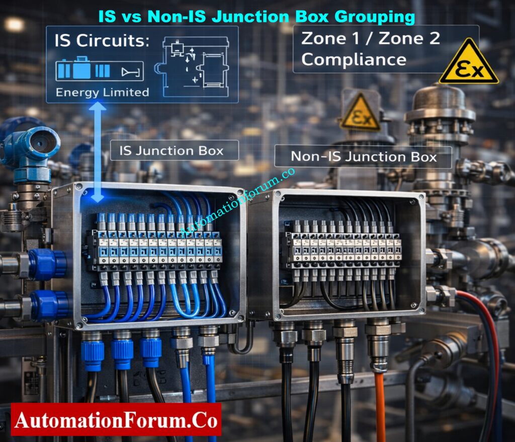
IS vs NIS Junction Box Grouping for Zone 1 and Zone 2 Areas
Even when there is a malfunction, Intrinsically Safe (IS) circuits are made so that energy is limited to keep things from catching fire. IS JBs are often used for:
- Analog transmitters in dangerous places
- Digital inputs from field switches in dangerous areas
- Instruments linked via safety barriers or isolators
Non-Intrinsically Safe (NIS) is a safety idea that says circuits should be built so that they don’t make sparks or get too hot when they are working normally. NIS, on the other hand, doesn’t protect as well as IS, hence it should only be utilized if area classification and project requirements allow it.
Important Practical Rules for IS and Non-IS Signal Segregation
Both analog and digital transmissions must follow IS and NIS criteria.
For instance:
- Even though it is merely a digital signal, a limit switch in a dangerous location must end in an IS-rated JB.
- A typical mistake on sites is to mix IS and non-IS signals in the same JB without properly separating them. This often means that work has to be done again during commissioning.
It is best to use specific IS junction boxes that are clearly marked, have blue terminals, and are kept separate from non-IS wire.
Instrument & JB Layout Explained Visually: What is Instrument location layout and Junction box location layout?
Role of 3D Engineering Tools in Junction Box Grouping Design
How 3D Tools Like Nevis Improve JB Grouping Accuracy
3D design tools like Nevis are becoming more and more important to modern instrumentation and automation engineering since they help with precision and synchronization throughout thorough engineering. 3D tools let engineers see the whole plant environment in a realistic and integrated way, which is different from typical 2D drawings.
Engineers can see well with 3D models:
- Field instruments and their exact installation locations
- Cable trays, ladders, and routing paths
- Structural beams, platforms, and supports
- Equipment layouts and access clearances
This level of visibility changes JB grouping from a theoretical documentation exercise to an actual engineering choice that is ready for the site. This cuts down on assumptions and design mistakes before construction starts.
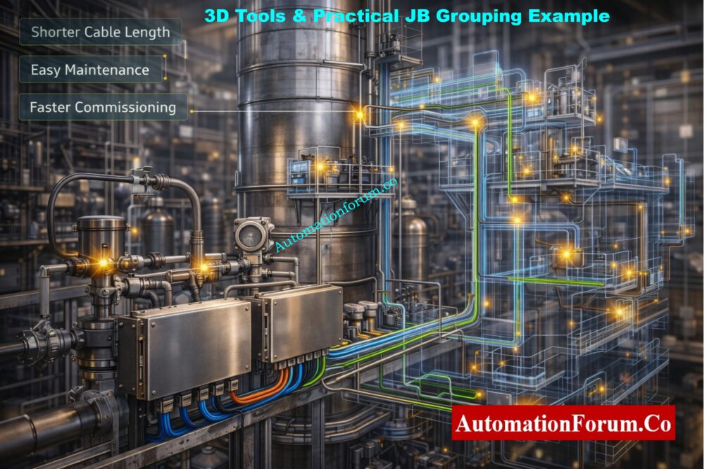
Advantages of 3D-Based JB Grouping for EPC and Site Execution
Using 3D engineering tools has a number of practical benefits for successful JB grouping:
- Put junction boxes near groups of field instruments to shorten cable length and cut down on voltage drop and signal loss.
- Put instruments in groups depending on where they will actually be installed, not on the rough positions suggested on 2D drawings.
- Make sure the cable tray routing is as efficient as possible to avoid tray congestion and too many cable crossings.
- Cut down on the total length of the cables, which will save money on installation labor, trays, and cables.
- Stay away from conflicts with pipes, equipment, and building parts so that you don’t have to do any extra work on site.
- Make site installation less confusing by clearly defining JB locations and coordinating them with other disciplines.
Engineers can make better, faster, and more reliable judgments by using 3D tools like Nevis instead of trying to figure out where JB is from 2D drawings.
Critical Grounding Rules Every Engineer Misses: Grounding and Bonding in Instrumentation and Control Systems
JB Grouping Checklist Before Finalizing Instrumentation Design
Before locking in the JB grouping design for an instrumentation project, the following checks must be carefully looked at to avoid having to do work again, safety problems, and delays in commissioning.
Engineering and Safety Checks for Junction Box Grouping
- Check the area categorization to see if the installation site is a safe region or a dangerous area, like Zone 0, Zone 1, or Zone 2.
- Make sure that all project specifications, client standards, and relevant international codes are followed. JB grouping rules may be different for each project.
- Make sure that Intrinsically Safe (IS) and Non-Intrinsically Safe (non-IS) circuits are completely separate, both physically and at the terminals.
- Check that the voltage levels are separate and that ELV, LV, and IS circuits are not all in the same junction box.
Signal Segregation and Cable Selection Checks in JB Grouping
- Check that all signal types, including as AI, AO, DI, DO, RTD, and thermocouple signals, are properly separated to avoid interference and wiring problems.
- Choose the right cable type for each signal, like a pair or triad arrangement, and make sure it has the right level of protection, such being insulated or armored, depending on the needs of the project.
- Make sure each junction box has enough spare terminals so that you may be flexible when you first set it up and make changes in the future.
- Make sure to include extra cable pairs so that you may add more instruments, expand the system, or change the loop without having to pull new cables.
Cold vs Hot Loop Checking Made Simple: Cold and Hot Loop Checking in Automation: Key Differences and Step-by-Step Procedures
Installation, Accessibility, and Maintenance Considerations
- Make sure that junction boxes are easy to get to for installation and regular maintenance, and that they don’t need scaffolding or special access tools.
- Make sure you choose the right gland based on the type of cable and the region classification to make sure it is protected from mechanical damage and the environment.
- Make sure there is enough room for the internal wiring inside the JB so that it can bend properly, end neatly, and be safe to operate in.
Environmental, IP Rating, and Mechanical Requirements for JBs
- Choose the right IP rating for the junction box based on the weather, chemicals, dust, or being outside.
- Depending on how likely it is to corrode and the atmosphere of the factory, pick the right JB material, like stainless steel, GRP, or aluminum.
- Make sure that the earthing and bonding are done correctly, with a connection between the gland plate, enclosure, and earth terminals.
Panel Heat Load Calculator Engineers Trust: Instrumentation Panel Heat Load Calculator – Complete Engineering Guide for Panel Cooling Design
Documents Required for Accurate JB Grouping in Instrumentation Projects
You must always check JB grouping against the following documents:
- Instrument Index
- I/O List
- Cable Schedule
- Loop Diagrams
- JB Wiring Diagrams
- Plot Plan and Layout Drawings
- Hazardous Area Classification Drawings
- Project Specifications and Standards
- Control System Architecture
- Cause and Effect Diagrams where applicable
Ex-Zone Cable Selection Engineers Must Know: What Cables to Use in Ex Zones: Complete Guide for Instrumentation & Control Engineers
Practical JB Grouping Example from a Chemical Process Plant
Distillation Column Instrumentation – JB Grouping Process Scenario
Think about a chemical process plant’s distillation column area, which has the following field instrumentation and devices:
- For continuous pressure monitoring, pressure transmitters are put on column trays, overhead lines, and reboiler circuits.
- Temperature transmitters, such as RTD and thermocouple sensors, that measure the temperatures of the process at different stages of the column
- Control valves with positioners are used to control the flow of feed, reflux, and bottom product.
- Level transmitters are put on the bases of columns and reflux drums to keep the level accurate.
- Limit switches on valves and dampers for feedback on position and interlocks
Recommended JB Grouping Approach for Field Instruments
A useful and easy-to-implement JB grouping method for this area would be:
- One specialized junction box for analog transmitters, installed near the distillation column to keep cable length short and make the signal more stable.
- A separate junction box for digital signals from limit switches, which keeps them distinct from analog loops and makes it easier to find faults.
- A separate Intrinsically Safe (IS) junction box for instruments that are put in dangerous places and meets all of the requirements for Zone 1 or Zone 2.
- A separate junction box for thermocouple signals keeps electrical noise and interference from other types of signals away.
This method of grouping JB in a systematic way cuts down on the amount of cabling needed, makes the signal better, and makes loop inspection and commissioning a lot easier.
Common JB Grouping Mistakes Observed During Site Execution and Commissioning
People often make the following mistakes during site execution and commissioning, thus you should prevent them:
- Putting both analog and digital signals in the same junction box might cause signal noise, readings that aren’t steady, and problems with troubleshooting.
- Mixing IS and non-IS signals without properly separating them, which can lead to safety violations and being turned away during inspection
- Not following the rules for digital signals in dangerous areas, thinking they don’t have to follow the laws for safety.
- Not provide spare terminals or cable pairs, which will cause big problems when you need to add to or change things in the future.
- Bad choice of where to put the junction box, which makes it hard to get to for installation, maintenance, and loop checking
Costly Cable Tray Mistakes EPC Teams Make: Avoiding Mistakes in Instrumentation Cable Tray Installation: A Guide for EPC Projects
Best Practices for Effective JB Grouping in Industrial Automation Projects
Following these best principles will help you make a strong and future-proof JB grouping design:
- When designing JB grouping, be sure to follow the project specifications, the client’s standards, and any relevant international codes.
- To make sure signal integrity and safety compliance, keep analog, digital, IS, and non-IS signals separate from each other.
- Use 3D engineering tools to find the best places for JB, which should be near instrument clusters and cable tray routes.
- When designing JB grouping, think about more than just the initial installation.
Proven Method Statement for Cable Termination: Method Statement for Instrumentation Cable Termination
Commissioning Engineer’s Pro Tip on Junction Box Grouping
From what I’ve seen in real life, many startup delays are due by wrong JB grouping instead of broken instruments. Before installation starts, always check JB grouping against loop diagrams and I/O lists. It’s much cheaper to fix problems during the design phase than after the fact.
Why 24VDC Fails in Real Plants: Why 24VDC is Not Always 24VDC – Real-World Troubleshooting for Analog and Digital Signals
Why Proper JB Grouping Is Essential for Safe and Reliable Industrial Automation
JB grouping in industrial automation and instrumentation is a lot more than just connecting wires. It is a very important engineering task that affects safety, dependability, commissioning time, and the cost of the plant during its whole life.
Engineers may make JB groups that are useful, safe, and ready for the future by following the rules for hazardous areas, using contemporary 3D tools like Nevis, and separating signals correctly. Instrumentation engineers that engage in EPC, site execution, commissioning, and plant maintenance need to be able to master JB grouping.
Mandatory Local Instrument Installation Checklist: Checklist for Installation of Local Instruments – Complete Guide for EPC, QA/QC and Commissioning
Frequently Asked Questions (FAQ) on Junction Box (JB) in Instrumentation and Electrical Systems
How to do junction box grouping?
To group junction boxes, field instruments are assigned to the right JBs depending on their location, type of signal, safety level, and voltage level.
Important steps:
- Group nearby instruments together
- Separate analog and digital signals
- Segregate IS and non-IS circuits
- Follow project standards and loop diagrams
- Provide spare terminals and cable pairs
What is JB in instrumentation?
A JB (Junction Box) is an enclosure used in instrumentation to join and end wires from field instruments like transmitters, switches, and control valves before sending them to control panels.
What is a Type 4 junction box?
A Type 4 junction box is a strong box that keeps dust, rain, splashing water, and water from hoses out. It can be used indoors and outdoors in industrial settings.
What is a JB in electrical?
A JB (Junction Box) is a safe way to connect, branch, or end power lines in electrical systems. It also protects connections from damage caused by the environment and machines.
What does JB stand for in electrical?
In electrical and instrumentation engineering, JB stands for “junction box.”
What are the three types of junction boxes?
The three most popular categories are:
- Instrumentation Junction Box: for signals from field instruments
- Electrical Junction Box: for circuits that power and light up things
- Intrinsically Safe (IS) Junction Box: for use in dangerous areas
82 Drawings Every Instrument Engineer Needs: 82 Essential Drawings and Documents for Instrumentation and Control Engineers