
- What Is an Intrinsic Safety Barrier?
- Types of Intrinsic Safety Barriers
- Intrinsic Safety Barrier Selection Procedure
- Intrinsic Safety Entity Parameters for Barrier Selection
- Zener Barrier and Galvanic Isolator Comparison
- Common Intrinsic Safety Barrier Selection Mistakes
- Intrinsic Safety Barrier Engineering Design Considerations
- Intrinsic Safety Barrier Troubleshooting Guide
- Intrinsic Safety Barrier Selection Checklist
- Frequently Asked Questions About Intrinsic Safety Barriers
- Conclusion: Intrinsic safety barrier selection
Selecting the correct intrinsic safety barrier is an important part of hazardous area instrumentation design. A barrier is not selected simply because the signal is 4 to 20 mA or because the device carries an intrinsic safety approval.
The complete circuit must be evaluated, including the hazardous area classification, field instrument, barrier, cable, control system, grounding arrangement, entity parameters, voltage drop and applicable certification.
An intrinsic safety barrier limits the electrical energy available to a hazardous area circuit by controlling voltage, current and power under normal operation and specified fault conditions. Zener barriers and galvanic isolators are common approaches, but their installation and electrical characteristics are different.
What Is an Intrinsic Safety Barrier?
How Does an Intrinsic Safety Barrier Work?
An intrinsic safety barrier is an interface installed between equipment in a safe area and an intrinsically safe field circuit in a hazardous area.
Its purpose is to prevent sufficient electrical energy from reaching the hazardous area to cause ignition under the conditions covered by the applicable intrinsic safety assessment.
Where Are Intrinsic Safety Barriers Used in Instrumentation?
The barrier works together with the field instrument and connecting cable. Therefore, the barrier should never be evaluated as an isolated component.
Typical applications include 4 to 20 mA transmitters, flow instruments, proximity switches, solenoid circuits, RTDs, thermocouples and other instrumentation signals.
Refer the below link for the Top Causes of Intrinsically Safe (IS) Loop Failure and How to Avoid Them
Types of Intrinsic Safety Barriers
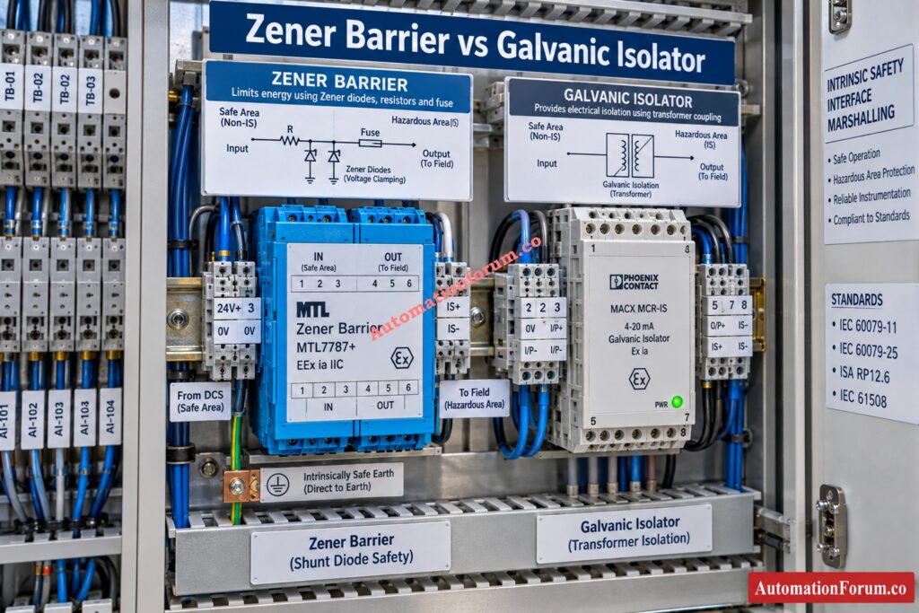
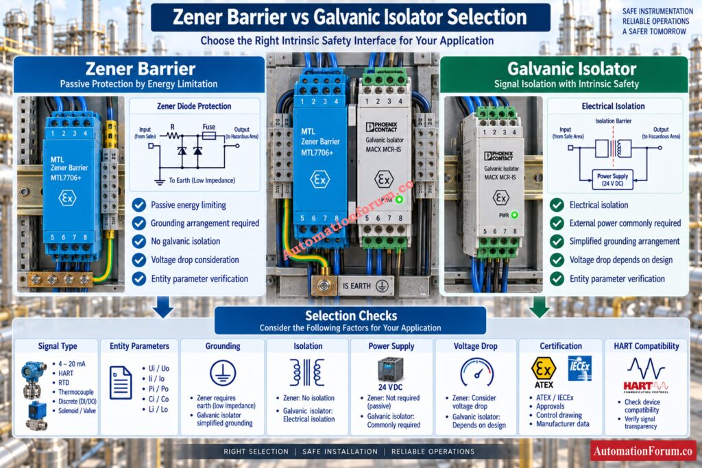
Zener Barrier for Intrinsic Safety Applications
A zener barrier normally uses zener diodes, resistors and a fuse to limit voltage and current. Excess energy is diverted through the grounding arrangement.
Because the circuit contains resistance, a voltage drop must be considered during loop design. A zener barrier also requires the grounding arrangement specified by its certification and installation documentation.
Compare IS And Explosion Proof Protection Before Equipment Selection: Difference Between Intrinsically Safe and Explosion-Proof
Galvanic Isolator for Hazardous Area Instrumentation
A galvanic isolator provides electrical isolation between the safe side and hazardous side while also providing the required energy limitation.
Many galvanic isolators require an external power supply and can also provide signal conditioning. Their isolation can simplify grounding arrangements, but the specific product certification and installation requirements must still be checked.
Calculate Earth Fault Current Before Your IS Loop Fails: IS Barrier Earth Fault Current Calculator | Intrinsic Safety Loop Design Tool
Intrinsic Safety Barrier Selection Procedure
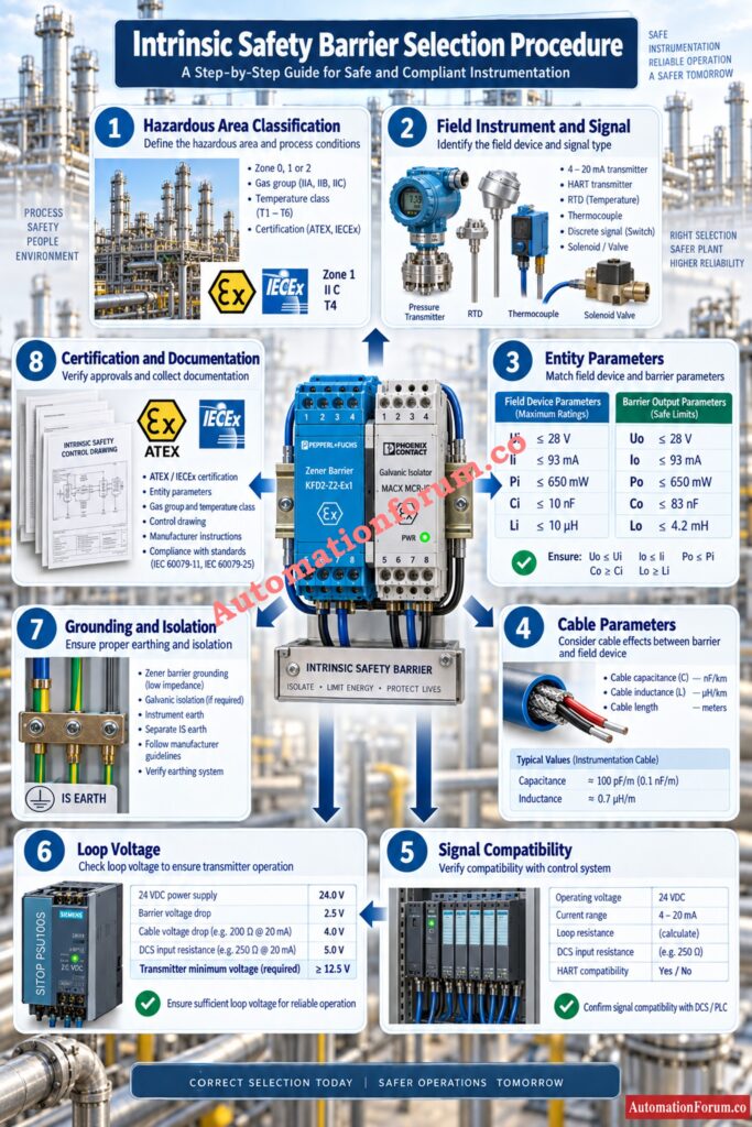
Step 1: Identify the Hazardous Area Classification
- Start with the hazardous area classification and project requirements.
- Check the applicable zone, gas or dust classification, gas group, temperature class, equipment protection requirements and required certification.
- The field instrument and associated apparatus must have compatible certification for the intended installation. Never select a barrier only from a general zone description.
Check Every IS Installation Detail Before Energizing Instruments: Installation Checklist for Intrinsically Safe Instrument (Apparatus)
Step 2: Identify the Field Instrument and Signal Type
Determine exactly what signal the barrier must handle.
Typical applications include:
- 4 to 20 mA transmitter
- Two wire transmitter
- HART transmitter
- Discrete input
- Discrete output
- Solenoid valve
- RTD
- Thermocouple
- Pulse signal
- Frequency signal
A barrier designed for one signal function should not automatically be assumed suitable for another signal function.
Trace PLC Input Failures Before They Disrupt Plant Operations: Top Causes of PLC Input Signal Failure in Plants
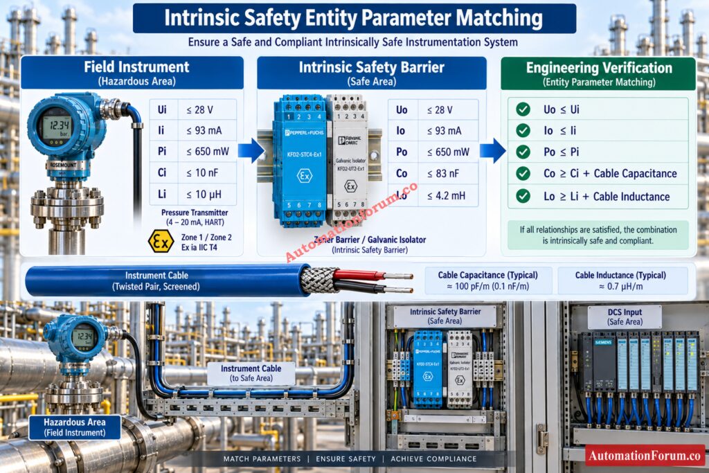
Step 3: Check Intrinsic Safety Entity Parameters
Entity parameters are among the most important checks in IS barrier selection.
For the field instrument, verify:
- Ui
- Ii
- Pi
- Ci
- Li
For the barrier, verify:
- Uo
- Io
- Po
- Co
- Lo
The basic engineering comparison is:
- Uo must be less than or equal to Ui
- Io must be less than or equal to Ii
- Po must be less than or equal to Pi
- The available barrier capacitance must accommodate the instrument and cable capacitance.
- Co must be greater than or equal to Ci plus cable capacitance
- The available barrier inductance must accommodate the instrument and cable inductance.
- Lo must be greater than or equal to Li plus cable inductance
These relationships are commonly used for entity concept verification, but the final acceptance must always follow the certified equipment documentation and applicable installation requirements.
Step 4: Check Cable Capacitance and Inductance
Cable characteristics can affect the intrinsic safety assessment, particularly on long instrumentation runs.
For example, consider a 500 metre cable with:
- Cable capacitance = 80 pF per metre
- Cable inductance = 0.8 microhenry per metre
Cable capacitance is:
500 × 80 pF = 40 nF
Cable inductance is:
500 × 0.8 microhenry = 400 microhenry
If the transmitter has Ci of 5 nF and Li of 100 microhenry, the barrier must provide sufficient Co and Lo for the combined values.
Required capacitance:
5 nF + 40 nF = 45 nF
Required inductance:
100 microhenry + 400 microhenry = 500 microhenry
This demonstrates why cable data should be checked before final barrier selection.
Understand 2oo3 Voting Before Designing Critical Protection Logic: 2oo3 Voting Logic Explained: How it Works, Why it is Used
Step 5: Verify Intrinsic Safety Signal Compatibility
Certification compatibility alone does not guarantee correct operation.
Check:
- Signal type
- Operating voltage
- Current range
- Barrier input and output characteristics
- Loop resistance
- Voltage drop
- Transmitter minimum operating voltage
- DCS or PLC input resistance
- HART communication requirements
A barrier can satisfy the intrinsic safety entity requirements and still cause an operational problem if its voltage drop is too high or its signal characteristics are unsuitable.
HART applications require particular attention to signal transmission through the selected barrier. The manufacturer documentation should confirm HART compatibility for the complete circuit.
Select Intrinsically Safe Cables Without Risking EPC Compliance: Intrinsically Safe Cables for ATEX Zones – Complete Checklist for EPC Engineers
Step 6: Calculate Intrinsic Safety Loop Voltage
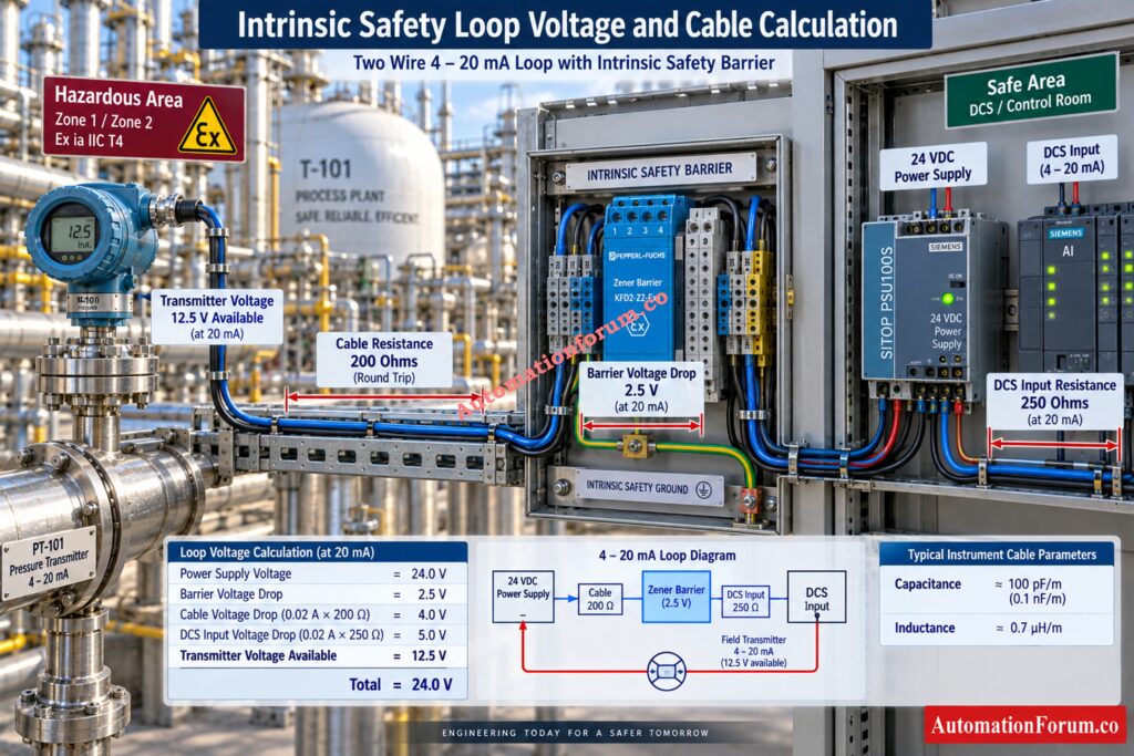
For a two wire transmitter, verify that sufficient voltage remains at the transmitter under maximum loop current.
Consider a simple illustrative circuit:
- Power supply = 24 VDC
- Barrier voltage drop = 2.5 V
- Cable resistance = 200 ohms
- DCS input resistance = 250 ohms
- Maximum current = 20 mA
Cable voltage drop:
0.020 × 200 = 4 V
DCS input voltage drop:
0.020 × 250 = 5 V
Voltage remaining for the transmitter:
24 minus 2.5 minus 4 minus 5 = 12.5 V
The calculated 12.5 V gives a tiny operational margin for a transmitter that needs minimum 12 V at 20 mA.
The actual transmitter requirement must come from its manufacturer documentation. This calculation should be performed during engineering rather than discovered during commissioning.
Calculate PFDavg Correctly Before Confirming Your Required SIL: SIF PFDavg / SIL Verification – Complete Guide + Online Calculator (IEC 61508 / 61511)
Step 7: Check Barrier Grounding and Electrical Isolation
- Grounding is an important distinction between barrier architectures.
- A zener barrier uses a grounding path as part of its energy limiting arrangement. The required grounding system must therefore meet the barrier certification and installation requirements.
- A galvanic isolator uses electrical isolation between circuits and generally does not depend on a dedicated IS grounding path in the same way as a grounded zener barrier.
- Instrument earth, IS earth and safety earth should not be treated as interchangeable terms. The project grounding philosophy and manufacturer installation instructions must be followed.
Identify Cable Differences Before Connecting Hazardous Area Instruments: Difference Between Intrinsically Safe (IS) and Non-IS Cables
Step 8: Verify Intrinsic Safety Certification and Documentation
Before approving the barrier, verify:
- ATEX certification where applicable
- IECEx certification where applicable
- Certificate number
- Protection concept
- Entity parameters
- Gas group
- Temperature class
- Installation requirements
- Manufacturer instructions
- Control drawing
- System certification
- Hazardous area documentation
- Project specifications
A barrier should never be selected only from its product name or signal description. The complete certified loop must be evaluated.
Master Ex Protection Levels Before Selecting Hazardous Area Equipment: Intrinsic Safety Protection Systems: Understanding Ex ia, Ex ib, and Ex ic
Intrinsic Safety Entity Parameters for Barrier Selection
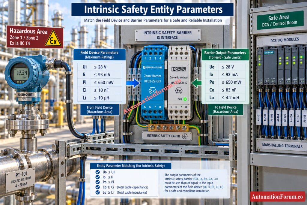
Consider a two wire 4 to 20 mA pressure transmitter installed in a hazardous area and connected to a DCS in a safe area.
What Are Ui, Ii, Pi, Ci and Li?
Illustrative transmitter parameters:
Ui = 30 V
Ii = 100 mA
Pi = 0.70 W
Ci = 5 nF
Li = 100 microhenry
What Are Uo, Io, Po, Co and Lo?
Illustrative barrier parameters:
Uo = 28 V
Io = 93 mA
Po = 0.65 W
Co = 83 nF
Lo = 2 mH
Cable parameters:
Cable capacitance = 40 nF
Cable inductance = 400 microhenry
How to Match Intrinsic Safety Entity Parameters
The entity checks are:
28 V is less than 30 V
93 mA is less than 100 mA
0.65 W is less than 0.70 W
Understand Explosion Proof Protection Before Choosing Hazardous Area Equipment: Exploring Explosion-Proof: Safety in Hazardous Environment
Intrinsic Safety Entity Parameter Calculation Example
Available capacitance after transmitter capacitance:
83 nF minus 5 nF = 78 nF
The cable requires 40 nF, so the capacitance requirement is satisfied in this illustrative example.
Available inductance after transmitter inductance:
2 mH minus 0.1 mH = 1.9 mH
The cable requires 0.4 mH, so the inductance requirement is also satisfied.
These values are illustrative only. Actual selection must use the certified parameters of the exact transmitter, barrier and cable.
Refer the below link for the Intrinsic Safety Entity Parameter Calculator for Reliable Hazardous Area Loop Design
Zener Barrier and Galvanic Isolator Comparison
| Parameter | Zener barrier | Galvanic isolator |
| Basic arrangement | Passive energy limiting circuit | Isolated active interface |
| Isolation | No galvanic isolation | Provides galvanic isolation |
| Grounding | Grounding arrangement is essential | Dedicated IS earth generally not required |
| Power | Normally passive | Commonly requires external power |
| Voltage drop | Must be considered | Depends on the specific module |
| Signal handling | Depends on barrier design | Depends on isolator design |
| Maintenance | Fuse and grounding checks may apply | Power and module health checks may apply |
| Selection focus | Entity values and grounding | Entity values, isolation and power |
GlobalSpec identifies zener barriers as passive devices and galvanic isolators as isolated interfaces, with both available for intrinsic safety applications.
Test Your Intrinsic Safety Knowledge With Real Plant Scenarios: Advanced Quiz on Intrinsic Safety Instrumentation Circuits in Oil & Gas Process Industries
Common Intrinsic Safety Barrier Selection Mistakes
- Selecting Only by 4 to 20 mA: A matching signal range does not prove intrinsic safety compatibility. Always verify entity parameters.
- Ignoring Cable Capacitance: Long cables can consume a significant portion of the permitted capacitance.
- Ignoring Cable Inductance: Cable inductance must be included when verifying the complete intrinsic safety circuit.
- Ignoring Voltage Drop: A barrier can introduce sufficient voltage drop to prevent a two wire transmitter from operating correctly.
- Incorrect Grounding: Wrong grounding can impact on the intended operation of a grounded barrier.
- Ignoring HART Compatibility: Standard analog barriers may not have the signal characteristics required for reliable HART connection.
- Ignoring Certification: Zone, gas group, temperature class and protection requirements must be verified against the actual certification.
- Not Checking the Complete Loop: The transmitter, barrier, cable and DCS or PLC interface must be evaluated together.
Discover The Engineering Reasons Behind Intrinsic Safety Selection: Why Choose Intrinsic Safety (IS) for Hazardous Area Instrumentation?
Intrinsic Safety Barrier Engineering Design Considerations
- Barrier selection should be coordinated with the complete instrumentation design.
- Review the instrument index, I O list, instrument datasheet, hazardous area drawing, cable schedule, junction box design, marshalling arrangement and DCS or PLC I O requirements.
- For SIS, ESD and fire and gas applications, additional project requirements may apply. The selected interface should therefore be consistent with the safety system design, approved architecture and applicable project documentation.
- During commissioning, the same information becomes important for loop checking and troubleshooting. A barrier that was selected correctly on paper can still produce field problems if wiring, grounding, termination or configuration differs from the approved design.
Understand Intrinsic Safety Before Designing Hazardous Area Circuits: What is Intrinsic Safety? Definition, Working Principle, Standards and Applications
Intrinsic Safety Barrier Troubleshooting Guide
| Problem | First check | Engineering verification |
| Low 4 to 20 mA signal | Measure loop voltage | Verify barrier drop and loop resistance |
| Transmitter does not power | Measure transmitter terminal voltage | Compare with minimum operating voltage |
| Intermittent signal | Check terminals and grounding | Inspect cable integrity and barrier condition |
| HART communication failure | Check communicator connection | Verify barrier HART compatibility |
| Incorrect loop current | Measure current at suitable points | Check loop resistance and barrier characteristics |
| Signal loss after installation | Check barrier wiring | Verify terminal assignment and certification |
| Unexpected voltage drop | Measure each section | Calculate complete loop voltage |
| Ground fault | Check grounding arrangement | Verify project grounding philosophy |
| Barrier channel failure | Check channel status | Follow manufacturer diagnostic procedure |
See Why Engineers Rely On Intrinsic Safety Protection: Why select Intrinsic safety?
Intrinsic Safety Barrier Selection Checklist
Before approving an IS barrier selection, verify:
- Hazardous area classification
- Applicable certification
- Signal type
- Ui and Uo
- Ii and Io
- Pi and Po
- Ci and Co
- Li and Lo
- Cable capacitance
- Cable inductance
- Loop resistance
- Voltage drop
- Transmitter minimum voltage
- Grounding requirements
- Isolation requirements
- HART compatibility
- Gas group
- Temperature class
- Manufacturer instructions
- Complete loop verification
Build Stronger Process Safety Through A Clear Shutdown Philosophy: Shutdown Philosophy: Engineering Documentation for Process Safety and Emergency Shutdown Systems
Frequently Asked Questions About Intrinsic Safety Barriers
What is an intrinsic safety barrier?
An intrinsic safety barrier limits voltage, current, and electrical energy entering a hazardous area circuit.
It helps protect intrinsically safe instruments by keeping the available energy below ignition levels.
How do I select an intrinsic safety barrier?
Select an IS Barrier by evaluating the hazardous area, kind of signal, certification, entity specifications and cable characteristics.
Also check voltage loss, grounding, HART compatibility and the whole instrument loop.
Verify SIL Performance Before Finalizing Safety Instrumented Functions: SIL Verification Report (Safety Integrity Level Verification Report)
What is the difference between a zener barrier and a galvanic isolator?
Zener barriers use components like zener diodes to limit the amount of electrical energy and require the grounding configuration specified.
A galvanic isolator offers electrical isolation between the safe area circuits and the hazardous area circuits.
What are Ui, Ii, Pi, Uo, Io, and Po?
Ui, Ii, and Pi define the maximum voltage, current, and power accepted by the field instrument.
Uo, Io, and Po define the maximum voltage, current, and power supplied by the associated apparatus.
Can an intrinsic safety barrier be used with a HART transmitter?
Yes, an intrinsic safety barrier can be used with a HART transmitter when the barrier supports HART communication.
The complete transmitter, barrier, cable, and control system loop must also meet the required compatibility checks.
Design Reliable FISCO Networks Without Missing Critical IS Requirements: Fieldbus Intrinsically Safe Concept (FISCO) Model for Foundation Fieldbus H1 and Profibus PA
What are the different types of intrinsic safety barriers?
Common types are zener barriers and galvanic isolators for certain intrinsically safe instrumentation applications.
Selection is based on the type of signal, isolation, grounding, parameters of the entity, certification and project requirements.
What are intrinsic safety standards?
Intrinsic safety installations are commonly designed with reference to the IEC 60079 series and applicable ATEX or IECEx requirements.
The specific requirements will be determined by the equipment certification, hazardous area categorization and project specifications.
What are the requirements for intrinsically safe circuits?
An intrinsically safe circuit shall limit electrical energy and satisfy applicable certification and entity parameter requirements.
What are intrinsic safety devices?
Intrinsic safety devices are certified equipment designed to operate in hazardous areas while limiting available ignition energy.
Examples include intrinsically safe transmitters, switches, sensors, barriers, isolators, and associated apparatus.
What is an IS barrier?
An IS barrier is an intrinsic safety barrier installed between safe area equipment and an intrinsically safe hazardous area circuit.
It limits electrical energy while providing the required interface between field instrumentation and control systems.
Which is an example of a safety barrier?
A zener barrier used between a safe area DCS and a hazardous area 4 to 20 mA transmitter is a common example.
A galvanic isolator certified for intrinsic safety is another widely used barrier interface.
What are intrinsic barriers?
Intrinsic barriers are interfaces designed to restrict electrical energy in instrumentation circuits connected to hazardous areas.
They help maintain intrinsic safety by controlling voltage, current, and power under specified operating and fault conditions.
Understand SIS SIF And SIL Before Designing Safety Systems: What is SIS, SIF and SIL? An In-Depth Guide to Functional Safety
Conclusion: Intrinsic safety barrier selection
Intrinsic safety barrier selection is a complete engineering verification rather than a simple component selection exercise. The correct barrier must satisfy hazardous area requirements, certification, entity parameters, cable characteristics, voltage requirements, signal compatibility, grounding requirements and control system interfaces.
For instrumentation engineers, the most important practice is to verify the complete loop from the DCS or PLC through the barrier and cable to the hazardous area instrument. This approach reduces commissioning problems and provides a clear technical basis for hazardous area instrumentation design.
GlobalSpec also highlights voltage, current, energy, application type and approval requirements as important considerations when selecting intrinsic safety barriers.
Refer the below link for the Intrinsic Safe Calculation for Instrumentation Design Engineers
