- Why This Distinction Matters for Instrumentation Engineers
- Definitions: Rangeability vs Turndown Ratio in Control Valve Selection
- Key Relationships and Formulas
- Short Numeric Worked Example
- Why Rangeability vs Turndown Ratio Matters in Control Valve Performance
- Installed Vs Inherent Valve Characteristics And Their Impact On Rangeability
- Types of Valves: Typical Turndown and Rangeability Ranges
- Comparison Table: Turndown Vs Rangeability Across Valve Types
- Sizing & Selection Rules – Worked Guidance
- Procurement Checklist & Specification Template
- Impact on Control Loop Performance and Maintainability
- Procurement and Specification Sample
- Common Mistakes and Troubleshooting
- Real Field Case: Oversized Valve Causing Low Flow Instability
- Design Rules Summary for Rangeability vs Turndown Ratio
- Practical Takeaways for Engineers
- FAQ on Rangeability vs Turndown Ratio in Control Valve Selection
Understanding rangeability vs turndown ratio is critical for proper control valve selection. Although these terms are often used interchangeably, they define different performance characteristics that directly impact control stability, maintenance cost and process safety.
Why This Distinction Matters for Instrumentation Engineers
In control valve engineering the terms rangeability vs turndown ratio are often confused. That confusion leads to oversized valves unstable control loops poor controllability at low flow and higher maintenance cost. This article explains precise technical definitions how manufacturers report each metric and why each matters when selecting valve body trim actuator and positioner. The content is written for experienced instrumentation and control engineers who need practical guidance for sizing procurement and troubleshooting.
You will find formulas a digit by digit worked example checklists you can copy into specifications and clear rules for avoiding common design mistakes. All calculations are shown using SI units with notes on imperial conversion where relevant. The objective is to provide engineering clarity so the selected valve not only passes the required flow but also controls it accurately across the full operating range. Additional emphasis is placed on verification testing and commissioning validation to ensure theoretical performance matches field performance.
Definitions: Rangeability vs Turndown Ratio in Control Valve Selection
What Is Turndown Ratio (Definition & Formula)
Turndown ratio is a sizing parameter that defines the ratio between the maximum controllable flow and the minimum controllable flow of a control valve.
Turndown ratio = Qmax ÷ Qmin
If a valve must control from 1.0 cubic meter per hour to 20.0 cubic meters per hour then:
20.0 ÷ 1.0 = 20
Required turndown = 20 to 1
Turndown focuses strictly on flow span and capacity. It answers whether the valve can physically handle both extremes of required process flow under acceptable pressure drop conditions.
What Is Rangeability (Controllability vs Capacity)
Rangeability describes how well a valve maintains a predictable proportional relationship between valve travel and flow across its stroke. It reflects controllability not just capacity. Rangeability depends on trim design leakage class stem friction actuator stiffness and positioner resolution.
How Manufacturers Report Each Metric
Manufacturers usually publish turndown as a ratio derived from Cv or Kv testing. Rangeability is often published for the trim assembly and may assume specific actuator and positioner conditions. A valve can meet turndown requirements but still fail to provide stable control if rangeability is inadequate.
Key Relationships and Formulas
Turndown Ratio Formula and Units
Turndown ratio = Qmax ÷ Qmin
Kv and Cv Relationships (liquid flows)
For liquids Q m3 per hour = Kv × sqrt DeltaP bar
Cv ≈ Kv ÷ 0.865
When to Use Kv vs Cv (SI vs Imperial notes)
Turndown defines the required span. Rangeability defines how effectively that span can be controlled. For procurement always specify both values and define the conditions under which rangeability is validated.
Troubleshoot 4–20 mA Loops Like a Pro: 4-20 mA Loop Troubleshooting with Loop Calibrators : A Practical Guide
Short Numeric Worked Example
Process Conditions and Problem Statement
Process fluid clean water at 20 degrees Celsius
Required flow range 1.0 to 20.0 cubic meters per hour
Turndown Calculation (Step-by-step)
Qmax = 20.0 m3 per hour
Qmin = 1.0 m3 per hour
Turndown = 20.0 ÷ 1.0
Result = 20
Required turndown = 20 to 1
Kv Sizing at Maximum Flow (Arithmetic shown)
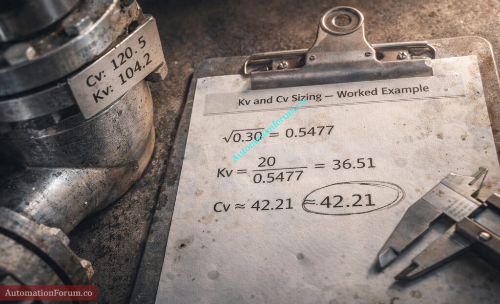
Assume allowable pressure drop across valve at maximum flow = 0.30 bar
Formula
Kv = Q ÷ sqrt DeltaP
sqrt 0.30 = 0.5477225575051661
Kv = 20.0 ÷ 0.5477225575051661
Kv = 36.51483716701107
Kv required ≈ 36.51 m3 per hour per sqrt bar
Convert Kv to Cv (Step calculation)
Cv ≈ Kv ÷ 0.865
Cv = 36.51483716701107 ÷ 0.865
Cv = 42.21368458613997
This valve must provide Kv approximately 36.5 at full opening while still delivering stable controllability at 1.0 m3 per hour. Verification of low travel flow data is essential to confirm rangeability performance.
Selecting the Right Wet Part Materials Made Simple: How to Select the Right Wet Part Materials of Sensors in Process Industries
Why Rangeability vs Turndown Ratio Matters in Control Valve Performance
Confusing rangeability and turndown creates serious control problems.
Low-Flow Accuracy and Nonlinear Gain
Adequate Kv does not guarantee good low flow control. Poor rangeability causes nonlinear gain and sluggish response.
Deadband, Hysteresis and Positioner Effects
Low resolution positioners and high friction increase effective minimum controllable flow leading to offset and instability.
Overshoot, Hunting and Oversized Valves
Oversized valves operate near seat where gain changes sharply. Controller output oscillates causing wear and loop instability.
Mechanical Wear, Erosion and Safety Considerations
Continuous near closed operation accelerates erosion and leakage particularly in abrasive or flashing services.
Minimum controllable flow directly impacts startup procedures relief sizing and emergency control logic.
Evaluating rangeability vs turndown ratio together ensures both capacity and controllability are satisfied.
Calculate Minimum Flow Using Turndown Ratio: How to Calculate Minimum Flow Rate for Flow Meters from Turndown Ratio?
Installed Vs Inherent Valve Characteristics And Their Impact On Rangeability

In control valve engineering the published rangeability value usually represents the inherent characteristic of the valve. However actual field performance depends on the installed characteristic which includes piping resistance pump curves and system pressure variations. Failure to evaluate installed behavior is one of the most common causes of low flow instability.
Why Turndown Ratio Can Make or Break Flow Meter Accuracy: Why Turndown Ratio is Important when Selecting a Flow Meter ?
Inherent Flow Characteristic
The inherent characteristic describes the relationship between valve travel and flow when the pressure drop across the valve remains constant. Laboratory Cv testing is performed under these controlled conditions.
Common inherent characteristics include:
- Linear
- Equal percentage
- Quick opening
Manufacturers typically publish rangeability based on inherent performance under constant differential pressure conditions.
Calibration vs Re-ranging Explained Clearly: Why Calibration Isn’t the Same as Re-ranging in Process Instrumentation
Installed Characteristic
In real systems the pressure drop across the valve does not remain constant. As flow increases friction losses in piping increase and available valve pressure drop decreases. This modifies the effective valve gain and alters controllability.
If the valve only consumes 10 to 20 percent of total system pressure drop at design flow the installed characteristic may become highly nonlinear at low travel.
Step-by-Step Control Valve Datasheet Preparation: How to Prepare Control Valve Datasheets: A Step-by-Step Procedure for EPC Instrumentation Engineers
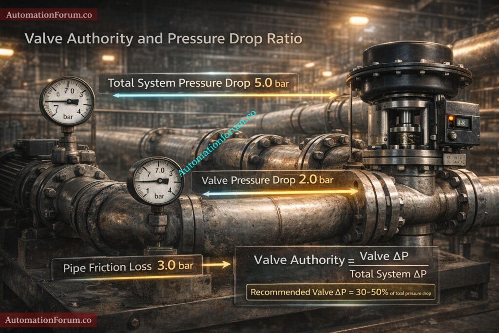
Why Pressure Drop Ratio Changes Effective Rangeability
Pressure drop ratio:
Valve DeltaP ÷ Total System DeltaP
Design rule:
Valve pressure drop at normal flow should typically be 30 to 50 percent of total available pressure drop for stable control.
Ignoring installed behavior often reduces practical 50 to 1 rangeability to less than 15 to 1 in actual plant conditions.
Control Valve Selection for Harsh Process Conditions: Control Valve Selection and Recommended Practices for Harsh Process Conditions
Types of Valves: Typical Turndown and Rangeability Ranges
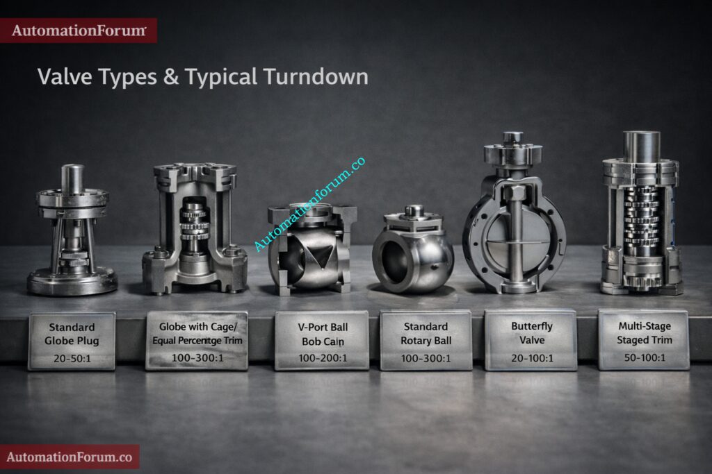
Different valve trims provide different performance characteristics.
Globe Valve Standard Plug
Practical turndown 10 to 20 to 1
Suitable for moderate range loops
Limited extreme low flow precision
Globe Valve Cage / Characterized Trim
Practical turndown 20 to 50 to 1
Improved rangeability
Common choice for critical process control
Supports anti cavitation staging
V-Port Ball / V-Notch
Practical turndown 20 to 70 to 1
High rangeability
Excellent for wide liquid flow ranges
Check erosion resistance
Standard Rotary Ball and Butterfly Valve
Practical turndown 5 to 10 to 1
Not suitable for tight modulation
Often used for coarse control
Practical turndown 5 to 15 to 1
Economical large bore solution
Limited low flow control accuracy
Multi-Stage / Staged Trims (Severe Service)
Practical turndown 50 to 200 to 1
Used for severe service high pressure drop cavitation control
Actual performance depends on actuator sizing positioner quality and installation conditions.
Use the Equal Percentage Valve Flow Calculator: Equal Percentage Control Valve Flow Calculator
Comparison Table: Turndown Vs Rangeability Across Valve Types
The following comparison summarizes typical performance ranges under clean liquid service conditions. Actual values vary by manufacturer and trim design.
| Valve Type | Practical Turndown | Practical Rangeability | Low Flow Stability | Severe Service Capability |
| Globe Standard Plug | 10 to 20 to 1 | Moderate | Fair | Moderate |
| Globe Cage Equal Percentage | 20 to 50 to 1 | High | Good | Good |
| V Port Ball | 20 to 70 to 1 | High | Very Good | Moderate |
| Standard Rotary Ball | 5 to 10 to 1 | Low | Poor | Limited |
| Butterfly Valve | 5 to 15 to 1 | Low | Fair | Limited |
| Multi Stage Severe Service Trim | 50 to 200 to 1 | Very High | Excellent | Excellent |
Selection must consider actuator stiffness stem friction and positioner resolution since trim capability alone does not guarantee system rangeability.
Proper Control Valve Sizing for Maximum Efficiency: How to Properly Size Control Valves for Maximum Efficiency?
Sizing & Selection Rules – Worked Guidance
Practical Selection Checklist (Numbered)
1 Define fluid properties temperature density viscosity and pressure.
2 Identify minimum and maximum flow including startup conditions.
3 Select allowable pressure drop.
4 Calculate Kv using Kv = Q ÷ sqrt DeltaP.
5 Compute turndown Qmax ÷ Qmin.
6 Add safety margin typically 20 percent.
7 Select trim with rangeability exceeding required turndown.
8 Size actuator with at least 150 percent torque margin.
9 Specify digital positioner with low deadband and high resolution.
10 Require factory performance verification.
Worked Logic Example
From the earlier example required turndown is 20 to 1.
Add 20 percent margin
20 × 1.2 = 24
Specify minimum turndown 25 to 1.
Evaluation
- Standard globe trim may not meet requirement.
- Cage equal percentage trim with 40 to 1 turndown and high rangeability is suitable.
- V port ball trim is suitable for clean liquids but erosion must be evaluated.
Actuator and positioner
Actuator must overcome maximum differential pressure plus friction with margin. Digital positioners with resolution better than 0.1 percent travel and hysteresis below 0.2 percent are strongly recommended to realize trim rangeability.
Control Valve Codes and Standards You Must Know: Codes and Standards for Control Valve Selection in Industrial Applications
Procurement Checklist & Specification Template
Required flow range
1.0 to 20.0 cubic meters per hour
Calculated Kv
Minimum 36.51 m3 per hour per sqrt bar
Required turndown
Minimum 25 to 1
Required rangeability
Minimum 25 to 1 preferred 50 to 1
Trim type
Cage equal percentage or V port
Actuator
150 percent torque margin including fail safe conditions
Positioner
Digital resolution 0.1 percent or better hysteresis 0.2 percent or better
Testing
Factory Cv test leakage test functional control test at minimum and maximum flow
Why Measuring Cv Is Critical for Valve Sizing: Why Measuring Control Valve Cv is Essential for Proper Valve Sizing ?
Impact on Control Loop Performance and Maintainability
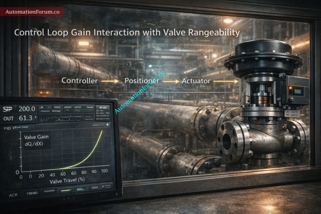
- Insufficient turndown forces the valve to operate near closed position where gain is unstable. This increases controller output movement wear and oscillation.
- Good rangeability improves loop tuning reduces hunting and enables predictive diagnostics.
- Maintenance intervals shorten when valves operate continuously at very low openings especially with erosive or cavitating fluids.
- Performance can be improved by selecting better trims using valve staging upgrading positioners and applying appropriate control strategies such as split range or cascade control.
Convert Cv to Cg for Gas Valve Sizing: Cv to Cg for Gases Conversion Calculator: Control Valve Sizing
Procurement and Specification Sample
- Valve shall control process flow from 1.0 to 20.0 cubic meters per hour.
- Required Kv greater than or equal to 36.51 m3 per hour per sqrt bar.
- Valve trim shall provide minimum turndown 25 to 1 and demonstrated rangeability greater than or equal to 25 to 1.
- Acceptable trims include cage equal percentage or V port with staging for high DeltaP. Actuator shall be sized with 150 percent torque margin.
- Digital positioner required with resolution less than or equal to 0.1 percent travel and hysteresis less than or equal to 0.2 percent span.
- Factory testing shall include Cv curve seat leakage and functional control testing at low and high flow.
Quick Kv to Cv Conversion Tool: Control Valve Kv to Cv Conversion Calculator
Common Mistakes and Troubleshooting
- Oversized valve causing oscillation resize or stage valves.
- Incorrect trim selection replace with characterized or staged trim.
- Low positioner resolution upgrade to digital high resolution device.
- Ignoring installed characteristic include piping effects in design.
- Missing verification testing require documented factory data.
- Undersized actuator recalculate torque and include safety margin.
Understanding Control Valve Flow Coefficient Cv: Control Valve Flow Coefficient (Cv) in Industrial Applications
Real Field Case: Oversized Valve Causing Low Flow Instability
A refinery cooling water control valve was originally sized for 100 cubic meters per hour based on maximum pump capacity. However normal operating flow was only 15 cubic meters per hour.
The installed valve operated at approximately 5 percent travel during steady state operation. Operators reported constant oscillation and hunting despite multiple PID tuning attempts.
Investigation revealed:
- Excessive Cv relative to required flow
- High valve gain at low travel
The valve was replaced with a smaller equal percentage cage trim sized for 40 cubic meters per hour maximum flow.
After replacement:
Operating travel went up to 35 to 45 percent.
- Loop stabilized immediately
- Oscillation eliminated
- Actuator wear reduced significantly
This scenario shows that just achieving turndown requirements is not enough to ensure steady controllability. You need to do a proper rangeability and installed characteristic analysis.
Streamline Your Flowmeter Selection Process: Streamlining Your Flowmeter Selection Process: Tips and Insights
Design Rules Summary for Rangeability vs Turndown Ratio
- Turndown sets the flow span that is needed.
- Rangeability tells you how much you can control within that range.
- Always look at the installed characteristic, not just the intrinsic data.
- Keep the valve DeltaP is between 30% and 50% of the overall system pressure drop.
- Add at least 20% to the calculated turndown as a design margin.
- Set the actuator torque margin to at least 150%.
- Require written proof of factory Cv and functional testing
- Don’t keep going if you’re less than 10% of the way there.
Following these principles ensures stable long term performance and reduced life
Practical Takeaways for Engineers
Rangeability and turndown ratio are connected, but they are not the same thing. Turndown sets the flow span that needs to be regulated, and rangeability shows how well that span can be controlled. To choose the right control valve, you need to look at the valve trim actuator and positioner as one control element. To make sure that the process works well, is stable, and lasts a long time, there must be clear requirements, enough safety margins, and proof that the factory tested it.
Key Factors That Affect Control Valve Performance: What are the factors that affect the performance of the Control Valve?
FAQ on Rangeability vs Turndown Ratio in Control Valve Selection
What is the difference between rangeability and turndown ratio?
The turndown ratio tells you how much flow a valve can tolerate between its highest and minimum flow.
Rangeability tells you how well and consistently the valve can control flow within that range.
What is rangeability in a control valve?
The ratio of a valve’s greatest controllable flow to its smallest stable controllable flow is called rangeability.
It shows how well the valve can keep stable, proportionate control throughout its stroke.
Why is turndown ratio important?
The turndown ratio makes sure that the valve can handle the process’s required flow range.
Too little turndown causes valves to be too big, the system to be unstable, and poor low-flow control.
How do you calculate rangeability?
To get rangeability, you divide the maximum controlled flow by the minimum controllable stable flow.
Rangeability = Qmax ÷ Qmin under specified test and installation conditions.