- What is Cv?
- Practical Applications of Cv Measurement
- Frequently Asked Questions (FAQ) on Control Valve Cv
- What Is the Cv Range for Stem-Guided and Cage-Guided Valves?
- Other Consideration for the Control Valve Engineers
- Selecting a Control Valve
- Avoiding Common Mistakes during Control valve CV Calculation
- Understanding Control Valve Cv Charts: Key Parameters and Applications
- Key Standards and Regulations for Control Valve Cv Charts
The Cv which stands for the control valve flow coefficient is a parameter this is paramount in the dynamic control valve field. An appreciation and quantification of CV enables accurate valve performance and system sizing together with fluid flow management. This guide aims to familiarize the reader with what Cv is, how it can be determined and how it may be used in valve design and specification. Furthermore, we provide answers to frequently asked questions concerning the control valve Cv.
What is Cv?
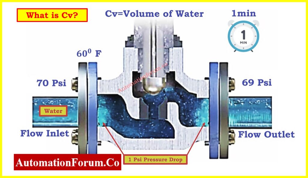
Valve flow coefficient or Cv is another measure that describes the ability of a valve to passing a fluid through it. Cv is referred to as the amount of water in gallons per minute at 60°F passing through an orifice with pressure drop of one psi across the valve. This value is measured under standard conditions in order to maintain comparability in valve comparison and valuation.
Cv Formula
The equation to calculate Cv is:

Where:
- Q= Flow rate in gallons per minute (GPM)
- ?P= Differential pressure across the valve in psi
- SG= Specific gravity of the fluid (1 for water at 60°F)
For example, If the flow rate (Q) is 10 GPM and the pressure drop (?P is 4 psi for water (SG=1):

The valve requires a Cv of 5 to handle a flow rate of 10 GPM with a 4 psi pressure drop. This calculation helps engineers determine the appropriate valve size for the system.
Why we Measure Control Valve Flow Coefficient (Cv)?
1. Standardized Comparison Over Valves
Cv enables engineers to distinguish flow capacities of various brands and models of valves. Cv has made the decision process for valves to be used in various industries simpler because it acts as a universal unit of measurement.
2. Proper Valve Sizing
One should ensure that the valve that is selected is not too big or small as this leads to inefficiency. An oversized valve may cause control hysteresis and an undersized valve may cause flow difficulties and pressure losses.
3. Preventing Cavitation and Choked Flow
Cavitation and choked flow are two major concerns that need to be considered during the design and analysis of the differential pressure systems.
- Cavitation on the other hand is the phenomenon that arises when the pressure of a liquid gets below its vapor pressure then vapor bubbles begin to form and burst. This can cause wear of the valve trims and also lead to a short lifespan of the system.
- Choked Flow occurs when flow is again limited by the formation of vapor bubbles in the pipe. It helps to size the valve by measuring Cv to avoid such problems.
4. System Efficiency and Performance
Understanding Cv enables engineers to determine how a valve will impact the system pressure and flow. This makes running of the organization smooth and also saves on bills that the organization may incur when using energy.
Refer the below link for the Control Valve Cv Calculation Excel Tool for Liquid, Gas, and Steam Services
Practical Applications of Cv Measurement
Example 1: Low Pressure Gas Application
- Conditions: Pressure < 300 psi, Cv ? 3
- Solution: A low-pressure regulator or control valve is suitable.
Example 2: Low Flow, High Pressure Drop
- Conditions: Pressure < 300 psi, Cv < 3
- Solution: A stem-guided high-pressure control valve is ideal for these requirements.
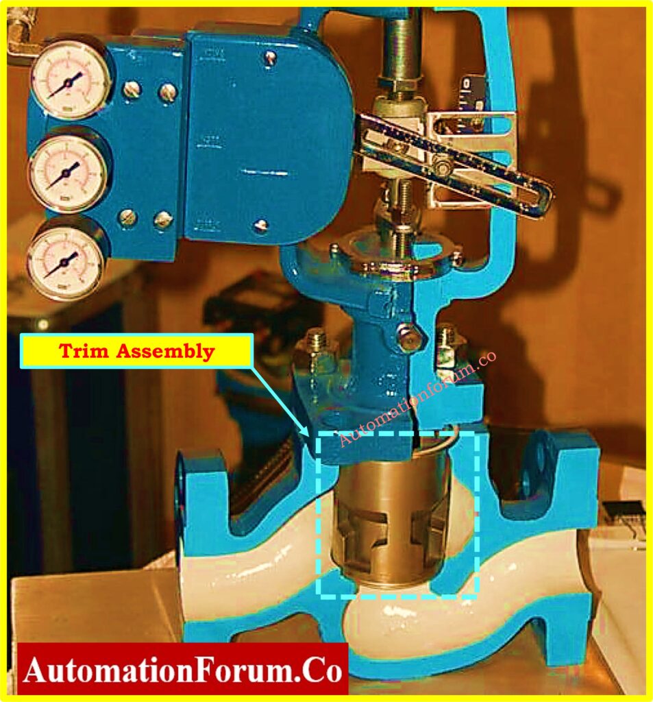
Valve Trim Options and Flexibility
Further flexibility has still been achieved in modern control valves as valve trim swaps are possible. Valve trims are replacement parts of the valve through which flow capacity or ‘Cv’ is regulated in response to changes in the system. Of special use is the ability to adjust the valve for changing conditions of operation without having to replace the valve in its entirety.
Advantages of Trim Swaps
- Cost-Effectiveness: RIt means expenses are cut when only trim is replaced instead of the valve as a whole.
- Minimized Downtime: Trim sizes are easier and less time-consuming to change than the valve since it requires replacement.
- Enhanced Versatility: Multiple flow requirements can be met by a single valve body based on the trim which can be easily changed..
- Extended Equipment Lifespan: Correct valve trims also safeguard the valve from problems such as cavitation and wear; hence, the valve works optimally in the future..
Practical Example
If system parameters change, for instance there is an increase in flow demand or shift in pressure demand, engineers can resize the valve by adding a new trim with a higher or lower value of Cv. This ensures that need of the valve is met in the operations without having to introduce new piping or make drastic changes.
Frequently Asked Questions (FAQ) on Control Valve Cv
What Is Cv in a Control Valve?
Cv stands for conversion factor that indicates how much flow a given valve can handle. The flow rate is the amount of water that was able to move through the valve head at a pressure drop of one psi while the temperature was 60 degrees Fahrenheit.
How Is Cv Calculated?
The flow coefficient (Cv) is calculated using the formula:

Where:
- Q is the gallons per minute (GPM) flow rate.
- ?P is the pressure differential in psi across the valve.
- SG is the Specific gravity of the fluid (dimensionless, 1 for water at 60°F)
What Is the Unit of Cv?
Cv is measured in gallons per minute (GPM) of water at a pressure drop of one psi at a temperature of sixty degrees Fahrenheit.
What Does CV Represent in a Ball Valve?
Cv indicates the number of gallons per minute a ball valve can pass under standard conditions. This value varies based on the valve’s design and size.
What Is Rated CV vs. Calculated Cv?
- Rated Cv is the flow coefficient that occurs when the valve is completely open.
- Calculated Cv: The Cv value at specific conditions, considering pressure drop, flow rate, and fluid properties.
Click here for Relationship Between Cv and Kv in Control Valves
Can Cv be Changed on a Control Valve?
Yes, by swapping the valve trim. This is common in high-pressure control valves that offer multiple trim sizes for different Cv requirements.
Why Is Cv Important in Valve Sizing?
Cv is the factor through which the right valve size for correct flow and efficiency is decided. It would be wrong to think that a small mistake in Cv can be responsible for such operational problems as cavitation or a high pressure drop..
What Is the Cv Range for Stem-Guided and Cage-Guided Valves?
- Stem-Guided Valves: Cv ranges from 0.34 to 21, which is most appropriate for low flow and high-pressure drop applications.
- Cage-Guided Valves: Cv value range from 28.6 to 1,091, ideal for handling high flow and pressure conditions.
Other Consideration for the Control Valve Engineers
In the selection of control valves and during the process of system revising, engineers have to consider several factors and make certain chances to improve the system.
Selecting a Control Valve
It is not only the valve flow characteristics that count when selection is under way. Engineers must evaluate the operational context and potential future changes:
- Use of Tools and Software: The majority of modern tools, such valve sizing software, let engineers enter system characteristics (such as temperature, pressure drop, flow rate, and fluid properties), and the software recommends the right valves based on these. These tools guarantee proper numerical computations of Cv values and instant cross-sectional comparisons of various types and sizes for valves.
- Medium and Environment Considerations: Such parameter as corrosiveness, viscosity and presence of solid particles should be considered to determine compatibility of the valve material and construction with the media. For instance, while a valve well suited for operating with steam may have somewhat dissimilar requirements as a valve that has to deal with abrasive slurry.
- Temperature and Pressure Ratings:This is important to avoid failures during the operation, by making sure that the selected valve can operate under the maximum pressure and temperature of the system.
Adapting to Changing Conditions for Future
None of the control valves can be rigid especially in respect to future changes in the system. Modern engineering practices emphasize versatility in valve design:
- Trim Swapping for Flexibility: Some valves have interchangeable trims which enable engineering professionals to change the Cv without making changes to the valve itself. For example When there is a need to transform a system that has more flow demand than before, one can just install a trim with a higher Cv. On the other hand, where the flow is low, exact control is achieved where a lower Cv trim is used.
- Accommodating System Upgrades: Valves with adjustable trims are useful where new components or additional processes are incorporated to a system since the flow characteristics of the existing valves can be modified to suit the new conditions.
- Mitigating Wear and Tear: However, in the long run the performance of the valve may be affected by any of the system dynamics for example pressure rises or change in types of fluids among others. Interchangeable trims are useful when recalibrated on a regular basis to achieve maximum output..
Avoiding Common Mistakes during Control valve CV Calculation
Even with advanced tools and guidelines, engineers should remain vigilant against common pitfalls in valve selection and application:
Oversized Valves:
- Consequences: Oversized valves often operate at lower-than-intended openings, leading to “hunting,” where the valve continuously adjusts to meet flow demands. This can cause control instability, reduced efficiency, and mechanical wear.
- Solution: Use precise Cv calculations to ensure the selected valve matches the system’s operating conditions.
Undersized Valves:
- Consequences: An undersized valve restricts flow, causing excessive pressure drops and potentially leading to cavitation or insufficient system performance.
- Solution: Ensure the calculated Cv falls within the operational range of the valve, accounting for both maximum and minimum flow conditions.
Ignoring System Dynamics:
- Consequences: Issues like rapid pressure changes, two-phase flow, or varying fluid temperatures can introduce unexpected stresses on the valve.
- Solution: Factor in potential variations during the design phase and choose valves with built-in tolerances for such conditions.
Click here for Control Valve Kv to Cv Conversion Calculator
Understanding Control Valve Cv Charts: Key Parameters and Applications
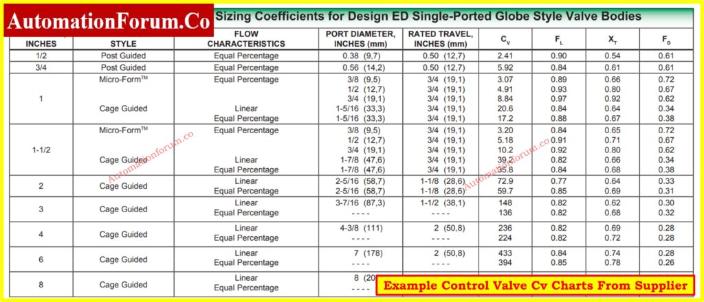
The control valve Cv chart is an essential tool for sizing and selecting valves in process control systems. Here’s a breakdown of the key elements and how they are used:
1. Cv (Flow Coefficient):
- Definition: Cv represents the valve’s flow capacity. It is the volume of water (in gallons per minute) that passes through the valve with a pressure drop of 1 psi.
- Usage: Higher Cv values indicate higher flow capacities, useful for selecting a valve size for specific flow conditions.
2. Flow Characteristics:
- Linear: The flow rate changes linearly with valve travel.
- Equal Percentage: The flow rate changes exponentially, giving finer control at low openings and larger changes at high openings. Common for throttling applications.
3. Port Diameter & Rated Travel:
- The port diameter (in inches/mm) refers to the valve opening through which the fluid flows.
- Rated travel is the valve’s maximum stroke or movement, determining how much the valve can open.
4. FL (Liquid Pressure Recovery Factor):
- Measures the pressure recovery of the valve. Lower values indicate a higher tendency for cavitation (formation of vapor bubbles in liquid flow).
5. XT (Pressure Drop Ratio Factor):
- Indicates the choked flow limit for liquids. It helps determine the maximum allowable pressure drop to avoid cavitation.
6. FD (Valve Style Modifier):
- A correction factor for specific valve designs that affect flow capacity. Lower values suggest more restrictive designs.
Refer the below link for the Cv to Cg for Gases Conversion Calculator: Control Valve Sizing
Key Standards and Regulations for Control Valve Cv Charts
ANSI/ISA S75.01.01 : Flow Equations for Sizing Control Valves
- Governs the calculation of Cv for control valves based on fluid properties, flow rate, pressure drop, and valve type.
- Defines standardized methods for presenting Cv values in charts.
IEC 60534-2-1: Industrial-Process Control Valves – Flow Capacity
- Provides guidelines for determining valve sizing coefficients, including Cv.
- Standardizes the testing and calculation methods for determining flow characteristics.
API Standard 526: Flanged Steel Pressure-Relief Valves
- Includes Cv data for relief valves but can be referenced for control valve flow capacity in certain cases.
Click here for Codes and Standards for Control Valve Selection in Industrial Applications
ASME B16.34: Valves – Flanged, Threaded, and Welding End
- Addresses the design of valves, including considerations for flow capacity and Cv calculation.
MSS SP-88: Diaphragm Valves
- Provides Cv charts and information specific to diaphragm valves.
BS EN 60534-2-3: Noise Prediction Method for Hydraulic Valves
- Offers Cv charts with considerations for noise levels in control valves under specific operating conditions.
Click here for Control valve Cv to Kv Conversion Calculator