- What is Loop checking:
- Loop testing procedure:
- Earthing and Continuity test:
- Insulation resistance test:
- Polarity test:
- Fault loop impedance test:
- What is loop checking in DCS?
- How to conduct a loop test?
- How to test loop impedance using a multi-function tester?
- Which one is the checking loop?
- What is an instrument loop?
- What is a calibration loop?
- How to perform loop checking?
- What is the difference between hot and cold loop checking?
What is Loop checking:
Loop checking is the final process before the commissioning of the processing system. Loop checking is the process that confirms the components wired correctly and also helps to ensure that the system is functioning as designed.
The loop checking checks the connection between each component in the control loop. A control loop consists of transmitter/sensor, process controller, final control element.
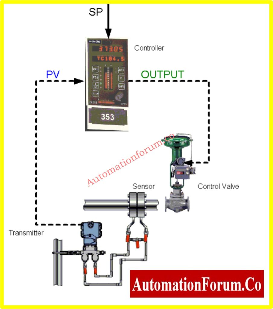
Before start, the loop check include, first list the number of loops, test actions, the procedure for documenting the check and plan should specify the type and characterization of signal. For example, differential flow meter generates a signal that has a square root relationship between flow rate and differential pressure.
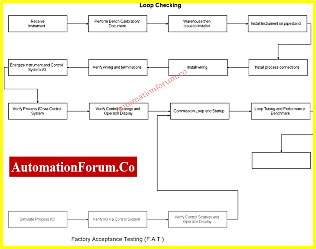
A factory acceptance of loop testing can be charted as shown below:
Loop testing procedure:
For loop checking the test to be carried out while there is no electric connection otherwise, the circuit to be tested should be isolated from the electric supply.
Earthing and Continuity test:
Earth resistance tests are required to confirm that the installed earthing system will cause the circuit protection devices to operate and maintain the integrity of the cable if there is a fault between the active parts and the exposed conductive parts.
The resistance from any point of the electric installation should be earthed. The resistance from the earthing electrode to the point where the main earthing conductor is connected to the neutral conductor of the supply system shall not exceed 5 ohms.
- Ensure that the electricity supply has been disconnected
- Connect an insulated copper conductor of suitable length(long lead) to one terminal of the ohm meter.
- Connect a standard length test lead to the other terminal of the ohm metre(short lead
- Connect the two leads together and zero the multimeter or if this is not possible. Record the resistance of the test lead
Main earth conductor:
- Connect the short lead to the earth electrode and measure the earth resistance of the main earthing conductor
- The resistance shall not exceed 5 ohms for the main earthing conductor
Earth continuity test:
- Using the long lead and zeroed meter, measure for each circuit, the earth conductor resistance from the circuit extremity to the switchboard.
- To confirm the measured values are less than those values as provided by table
- This test is applicable to all circuits, including socket outlets circuit, lighting circuits and fixed equipment circuits.
Insulation resistance test:
The insulation resistance tests to ensure there is no current flow between conductor and ground or insulation surface. If there is no current flow the wire could prevent electric shock hazards, fire hazards and equipment damage.
Test procedure:
- Ensure all protective device in the circuit is switched ON.
- Set the insulation tester to megaohms
- Connect an insulation tester cable to the main earth bar and the other cable to the active and neutral connected together. Do not perform tests between assets and neutrals.
- Measure the insulation resistance of the total installation, if the resistance is greater than 1 megaohm then the normal to work.
- If resistance is less than 1 megaohm disconnect the appliances. Then test the circuit separately to ensure that the insulation resistance of both the circuit and the appliances complies with the following
- Not containing a heating element- is not less than1 mega ohm or
- Containing a heating element-is not less than 0.01 mega ohm
Polarity test:
Polarity tests are carried out to ensure that the correct connection of the active, neutral and ground conductors to the electrical equipment ensures that the switches are not installed in neutral conductors.
Test procedure:
- Isolate the active conductors by turning the main switch OFF and tagging
- Confirm the consumer and sub main cables by simply testing from the point of distribution board to the main switch board using an ohm meter and long test loads. Test result= 0 ohms
- Confirm the switching of the active conductors using an ohm meter with the long cable connected to the active conductor on the board and the short wire connected to the terminals of the switch as follows
- Switch ON = 0? for both terminals, Switch OFF = 0? for one terminal and infinite for the other terminal.
- With the MEN link in place, confirm the polarity of the sockets using a 10? resistor and an ohm meter. Connect the 10? resistor between the active circuit conductor and the neutral bus, then connect the multimeter cable to the ground terminal and the second cable to the active terminal. Test the resistance value for.
Fault loop impedance test:
This test is performed to confirm that the impedance value of the fault loop of each circuit will be low enough to guarantee the operation of the protection device during a fault.
Test procedure
- Energize all circuits
- Using the fault loop impedance meter, proceed to the equipment to be tested and measure the impedance of the ground loop at this point. Repeat for other elements in the circuit
- The measured value must be less than the maximum values as in the Wiring Rules
- If an RCD works during the test, the results of the test can be considered satisfactory.
What is loop checking in DCS?
In a Distributed Control System (DCS), loop checking is the process of checking the whole control loop, from the field instrument to the DCS, before it goes live. It makes sure that all of the following are working correctly: signal continuity, alarm functionality, calibration range, setpoints, and custom control signals.
How to conduct a loop test?
A loop test is when you check each part of a control loop to make sure it works well. Common steps include reviewing the paperwork, making sure the instrument is in the right place, doing visual inspections, testing the wiring for continuity, and making sure the signal is sent to the control system.
How to test loop impedance using a multi-function tester?
- On the MFT-Pro, choose the Earth Fault Loop test mode.
- Get to the side of the installation where the power comes in.
- Attach the first test lead to the active terminal.
- Attach the second test lead to the neutral terminal.
Which one is the checking loop?
In process control, the “checking loop” is the loop that is being verified before it is put into service. Loop checking makes sure that every device in the loop is wired correctly, installed correctly, and works as it should.
What is an instrument loop?
An instrument loop is a group of connected devices, like transmitters, controllers, and final control elements, that work together to measure and regulate a process parameter.
What is a calibration loop?
Loop calibration checks that the whole measurement chain, from the sensor to the wire to the receiving device (such a recorder or DCS input), is correct. Changes are made to make sure the loop reaches the appropriate levels of accuracy.
How to perform loop checking?
Typical steps include:
- Going over loop drawings, calibration certificates, and the setup of the control system.
- Locating the instrument in the field.
- Checking visually for proper installation, marking, and wiring.
- Checking the correctness of signals and testing electrical connections.
What is the difference between hot and cold loop checking?
- Cold loop checking: This is done when the system is turned off and checks the wiring and signal routes without any live process signals.
- Hot loop checking: Done with the system on and working to make sure that live process signals are being processed and shown accurately in the control system.
.)