The valve actuator is a part of the control valve assembly fitted to it.
- In any control loop, the valve actuator receives a control signal for the system to move the valve to either a fully open or fully closed position or to remain in an intermediate position depending upon the control signal used.
- The control valve operation involves the positioning of these moveable parts such as a plug, ball, or vane relative to the stationary seat of the valve.
The two basic functions performed by valve actuator are:
- To drive the moveable parts of the valve to the required position through the control signal sent by the controller.
- To provide default positioning of the valve when drive power is not available i.e. to open or close the valve or to hold steady in the current position.
What are the common types of actuators used in control valves?
An actuator provides the power to operate the valve parts under normal flow conditions.The common types of actuators used are classified on the basis of the type of supply power applied to them, and the type of movement.
1. Pneumatic Actuators :
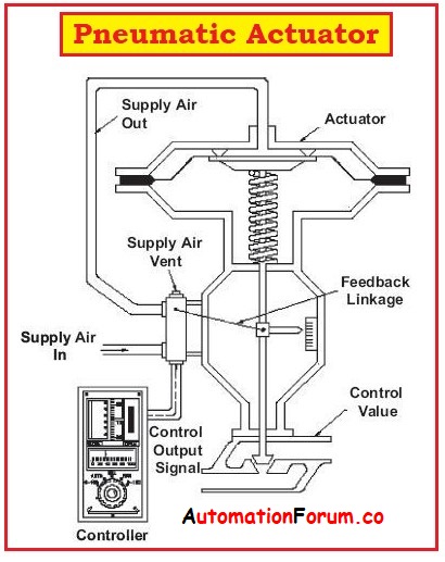
- These pneumatic actuators are the most common and are widely used actuation methods.
- These actuators are known as fluid-powered actuators.
- In this type, the air supply is used to drive the actuators typically the supply air is 3psi to 15psi.
- These pneumatic actuators are versatile and these are used where electric power supply is not available.
- The pneumatic actuators for valve operation use the cylinder coupled mechanism. In this, the linear motion generated in the cylinder is converted to the quarter turn motion.
- These actuators are quarter turn and multi-turn.
- For most applications, these actuators can deliver the required forces with adequate travel speed.
- The cylinder is moved using pressurized air in the case of pneumatic actuators.
- On loss of drive power, these actuators provide a fail-safe response by including spring sets in their design.
- These actuators are inherently safe against explosion hazards.
- The common designs include pistons, diaphragms, or rotary vanes.
- In addition, an opposing spring allows for positive shut-down in case of emergencies
2. Hydraulic Actuators :
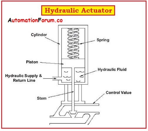
- The hydraulic actuators use the liquid pressure to move the valve mechanism.
- The piston is more preferred than the diaphragm in the case of hydraulic actuator designs for converting the fluid pressure into mechanical force.
- These hydraulic actuators are used in large isolating valves in gas pipelines because these actuators generate a huge amount of mechanical force.
- Due to the non-compressibility of hydraulic oil, these actuators exhibit a stable positioning.
- Some actuator designs are called Electro-hydraulic valve actuators because of the combination of hydraulic (fluid) and electric power.
- An Electro-hydraulic valve consists of an electrically driven hydraulic unit that supplies pressurized fluid.
- For isolated locations,electro-hydraulic actuators are ideal where there is a need for precise control of valve plug position due to the unavailability of pneumatic supply pressure.
- These actuators have a wide range of capabilities, the smaller actuators deliver a few inch pounds of torque and the larger actuators deliver a million-inch pounds of torque.
- Hydraulic actuators are used in heavy loads like large construction equipment often operated by hydraulic pressure.
- Hydraulic actuators are cost higher compared to pneumatic and electric actuators.
- These actuators tend for fluid leakage.
3. Electric Actuators :
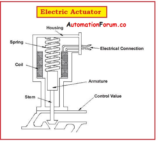
- These actuators use an electric supply and gear reduction system to drive the valve in linear or rotational travel for large isolating valves.
- They can be used for ON-OFF control in larger applications.
- These actuators are found in power plants, the process industries like the pharmaceutical industry, sugar industry, distilleries, and so on.
- These actuators are capable of the quick opening of the valve.
- These actuators are powered by single-phase or three-phase electric motors to drive gears and spurs that engage the valve stem for the opening or closing of the valve.
- These valves for manual operations include a declutching mechanism and a hand wheel in case of power failure.
- For quarter turn the final control element is positioned only in one quadrant that offers 90 degrees of rotation.
- These actuators are compact and require less power and can be used for smaller valve applications.
- For fail-safe operation, these actuators can be configured with an emergency power supply such as a battery.
The operation of pneumatic and hydraulic actuators is similar to each other but differs slightly in cylinder movement.
But the difference is that in hydraulic actuators the cylinder movement is done by incompressible fluid from the pump, while.
In pneumatic actuators, the cylinder movement is done by compressed air by compressors to drive large equipment that has large bore cylinders.
4. Diaphragm Actuators :
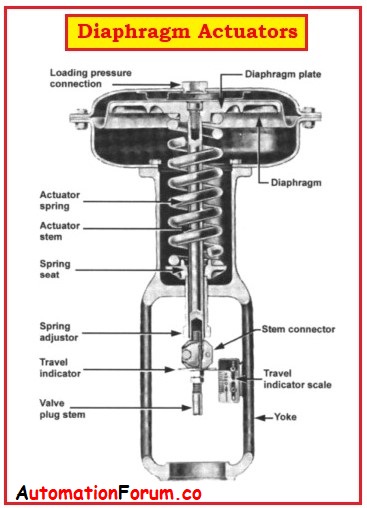
- These diaphragm actuators are common types of pneumatic actuators.
- For sealing the pressure chamber these actuators use a flexible diaphragm to deliver a substantial drive force for a relatively low pressure due to the large cross-sectional area.
- The large actuating force is generated from a diaphragm actuator with relatively small pressure and a large area.
- These actuators use the diaphragm chamber principle.
Classification of diaphragm actuators :
The diaphragm actuators are broadly classified into:
(1) Linear diaphragm actuators
(2) Rotary diaphragm actuators
The rotary diaphragm actuators have a crank arm and pinion gear for converting linear motion to a rotatory motion at the range of 90 degrees.
How does a diaphragm actuator work ?
In the case of direct-acting actuators, an instrument air enters the upper area of the diaphragm and pushes the diaphragm downwards.
The air pressure transferred to the diaphragm controls the spring torque that is located under the diaphragm and pushes the valve stem downwards for closing the valve.
What are the different types of linear actuators?
There are three different types of linear actuators used
- Hydraulic actuators,
- Pneumatic actuators, and
- Electro-mechanical actuators.
Where is the linear actuator used ?
- The linear actuators are used to push or pull the body using the same force.
- The linear actuators are used for lifting, lowering, sliding, adjusting, and tilting objects.
- The linear actuators in robotics are used to control repetitive movements.
- The linear actuator controls the force applied and the rate of acceleration.
What is the importance of linear actuators ?
- The linear actuators make movement possible in robotics applications.
- These linear actuators allow the robotic machinery to interact with its environment through wheels, clamps, arms, and legs.
What is the lifting capacity of a linear actuator ?
The lifting capacity depends upon the actuator but ranges from 5 kg to 1000 kg.
Why are linear actuators so expensive ?
The high force linear actuators are more costly than small or micro linear actuators because high force linear actuators have a larger motor with large gearing and require more power supply.
What is a mechanical linear actuator ?
The mechanical linear actuators translate rotary motion to linear motion these actuators derive the power from an external source.
What does a rotary actuator do ?
- A rotary actuator is a type of pneumatic cylinder that provides a turning or angular movement,
- These actuators allow a stroke in an oscillating motion through a defined angle.
- These are highly durable and provide high torque.
Direct Acting and Reverse Acting Actuators :
Pneumatic diaphragm actuators receive air supply as a signal from a controller or positioner.
These are used for sliding stem control valves like globe-style valves. The pneumatic actuation system is accomplished in two ways as
- Direct Acting.
- Reverse Acting
Direct Acting Diaphragm Actuators :
In direct acting, the air pressure pushes the diaphragm in the downward direction and the diaphragm extends the actuator stem which in turn closes the valve. The valve stem is retracted by a compression spring when the air pressure from the valve is released. In this case, the valve is nominated as an Air to close. Fail Open (ATC – FO) valve.
Reverse Acting Diaphragm Actuators :
In reverse acting the air pressure pushes the diaphragm in the upward direction and the diaphragm pulls up the actuator stem which in turn opens the valve. The stem is pushed down by the compression springs when the air pressure from the valve is released. In this case, the valve is nominated as an Air to Open. Fail Close (ATO – FC) valve.
Field – Reversible Multi-Spring Actuators :
The actuators can be gathered for direct acting or reverse acting by altering the air pressure connection points to the top or bottom of the valve actuator.
Piston Actuators :
The compressed air in the piston actuator is supplied to the cylindrical chamber containing a solid piston to drive a piston rod. This piston rod is coupled to the valve stem by a coupling mechanism.
What are the types of piston actuators ?
There are two types of piston actuators: single-acting and double acting.
- Single-acting actuators drive the piston against the spring.
- The double-acting actuators have two cylinders,
Instrument air is supplied to the drive side and the opposing side is vented to the air return circuit.
Considerations in Choosing a Valve Actuator :
Compatibility:
Here are a few important factors to be considered for choosing the appropriate valve actuators for particular applications.
- The compatibility factors define the source of power that is available.
- Depending upon the available source of energy the choice is made in some locations electrical supply may not be available, and there is the choice of using a pneumatic or hydraulic valve actuator.
- Electric actuators require an electric supply of 110 VAC to operate.
- Pneumatic actuators require an instrument air supply in the range of 40 and 120 psi
Temperature Range:
- The operating temperature varies for various actuators
- Pneumatic actuators operate at a temperature range of -20°C to 120 °C.
- Electric actuators operate at a temperature range of -40°C to 65°C.
Hazardous Areas:
- In toxic environments or hazardous environments, pneumatic actuators are often preferred due to their explosion-proof nature.
- Electric actuators used in hazardous or toxic environments must have a NEMA VII enclosure to protect them from explosions.
Sizing and Force:
- Force is the physical quantity that refers to the total torque required for the valve, which means the total force required for the valve to move the closure element from the open to the close position.
Supply pressure:
- It is the most important sizing factor to be considered.
- An actuator must develop enough torque for operating the valve at the minimum or maximum pressure applied.
- The actuator must be for the maximum potential pressure.
- The regulators and safety relief valves are oversized.
Speed:
- The speed instructs the power requirements of the actuator.
- It consumes maximum power for the full opening and closing of the valve within a short period.