- Step by Step Calibration Procedure for Mass Flow Controller
- Step 1: Tools Required for Mass Flow Controller Calibration
- Step 2: Safety Precautions
- Step 3: Prepare Calibration Setup for Mass Flow Controller
- Step 4: Calibration Procedure of Mass Flow Controller
- Step 5: Recording Calibration with Linearity Check
- Step 6: Completion of Calibration
- Step 7: Calibration Report Preparation and Validation
- Calibration Standards for Mass Flow Controller
Step by Step Calibration Procedure for Mass Flow Controller
The detailed procedure outlined below provides a step-by-step guide for calibrating a Mass Flow Controller (MFC) using a standard portable reference mass flow meter (MFM), applicable in either the process area or a flow calibration lab.
Step 1: Tools Required for Mass Flow Controller Calibration
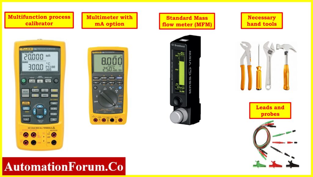
- Standard Multimeter with mA option
- For supplying a 4 to 20 mA signal, use a loop calibrator or multifunctional calibrator for simulating the setpoint.
- Reference standard Mass Flow Meter(MFM).
- Test leads and probes.
- Standard fittings for connecting reference Mass Flow Meter(MFM).
- Standard tools.
- Soft Cloth for cleaning.
Step 2: Safety Precautions
- For information on fundamental safety, general recommendations, and calibrating operations in process industries, please click the link provided below. Basic Safety and General Considerations for Process Industries Calibration Process
- In order to configure the mass flow controller in manual mode for the control loop and MOS mode for the ESD loop, consult the panel operator.
- Identify the Mass Flow Controller: Locate the specific mass flow controller you wish to calibrate. Verify that it is the correct MFC for the task and make a note of any relevant information, such as the manufacturer, model number, flow range, gas type, etc. Alway refer the instrument data sheet of the mass flow controller
- Turn off the Power Source with help of instrument loop diagram : Ensure that the power supply to the MFC is turned off at the source. This may involve turning off a breaker, unplugging wires, or taking any necessary precautions to cut off the electrical power.
- Depressurize the System: Depending on the type of system and process, you may need to depressurize it before disconnecting and calibrating the the MFC. Follow the appropriate steps for depressurization, such as venting the pressure or isolating the system.
- Unplug Electrical Connections: Carefully disconnect the electrical connections from the MFC. Be sure to follow safety precautions, such as wearing insulated gloves, and avoid damaging the wires or connectors.
- Disconnect gas tube Connections: Remove the process gas connections from the MFC. This might involve removing fittings, releasing clamps, or any other type of connection. Be careful not to damage any fittings or tubing during this process.
- Always adhere to the manufacturer’s guidelines and any regional safety standards when working with MFCs or other process equipment. Safety should be a top priority.
- To prevent unintentional startup or operation, follow all applicable lockout/tagout protocols. Ensure that the MFC is kept separate from the process and properly labeled to indicate its disconnected status.
- Modify the Procedure as Needed: Be aware that specific equipment and process areas may require modifications to this general procedure. Always adapt your approach based on the unique circumstances and equipment you are working with.
How do you Calibrate a Mass Flow Controller ?
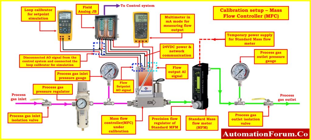
Step 3: Prepare Calibration Setup for Mass Flow Controller
- It is necessary to install the mass flow controller calibration equipment in a location free from electromagnetic interference and vibrations. Additionally, the area needs to be well-lit and ventilated.
- Gather all of the equipment and tools that are required for calibration.
- Identify and locate the outlet of the mass flow controller (MFC) from which the process gas flows.
- Carefully disconnect the tubing from the outlet of the MFC to prepare for the calibration.
- Using standard fittings and tubing, install a standard reference mass flow meter in series with the mass flow controller.
- Ensure that the standard reference meter is securely connected and properly calibrated to provide accurate readings.
- Set up a temporary power connection to the standard reference mass flow meter. This is essential for the reference meter to function during calibration.
- Follow any specific wiring diagrams or instructions provided by the manufacturer of the reference meter to ensure proper power connection.
- To measure the actual flow output from the mass flow controller, install a multimeter in the milliampere (mA) range in series with the MFC’s flow output.
- This allows you to monitor the MFC’s output signal during the calibration.
- Disconnect the set point signal (AO) of the mass flow controller. This signal usually controls the desired flow rate.
- Connect a loop calibrator or multifunction calibrator to simulate a high flow set point. This step is essential to determine how well the MFC performs at maximum flow.
- While calibrating, either use the calibrator to simulate a high set point command or set the high setpoint from the control system control room (if available) to keep the control valve of the mass flow controller fully open.
- Ensuring that the control valve is fully open at the high flow setpoint helps test the upper range of the MFC.
- Once all the connections are in place, double-check that all fittings are tight and secure in the process connections to prevent any process gas leaks. Gas leaks can affect calibration accuracy and pose safety risks.
- With the setup in place and all connections secured, you can proceed with the calibration process.
How do you calibrate a thermal mass flow meter?
Step 4: Calibration Procedure of Mass Flow Controller
- Switch on and Verify the power supply for both the mass flow controller and reference mass flow meter.
- Configure the standard mass flow meter to the specific gas type, pressure, and flow range as specified in the data sheet of the mass flow controller.
- This step ensures that the calibration aligns with the expected operational conditions.
- Prepare the reference mass flow meter by fully closing the precision regulator. Simultaneously, open the inlet and outlet gas process valves.
- By doing this, you establish the initial conditions for the calibration process and enable the gas circuit to function properly.
- Utilize a loop calibrator or make adjustments from the control room to set a high set point for the mass flow controller.
- This action ensures that the control valve of the mass flow controller remains fully open, allowing you to test its performance across its entire range.
- Verify that the pressure settings are in accordance with the prevailing process conditions.
- If necessary, make adjustments using an installed inlet regulator and pressure gauge to ensure the pressure aligns with your specific requirements.
- With the gas circuit active, switch on the multimeter. The multimeter should display a reading of 4mA, while the mass flow reading in the control room should register zero. If not, fine-tune the mass flow controller’s zero adjustment parameter until it reaches the desired 4mA output and the control room display reads zero.
- To assess the full operational range of the mass flow controller, use the reference mass flow meter’s precision regulator.
- Adjust the mass flow rate to reach 100% of the mass flow controller’s specified range. Ensure that the multimeter now displays 20mA, and the control room’s mass flow reading also indicates 100% of the range.
- Should any discrepancies or errors arise in the mass flow rate readings, address them by adjusting the span adjustment in the mass flow controller. This step ensures that the mass flow controller’s performance is accurate and reliable across the entire range.
- Always keep in mind that the specific calibration procedure may differ based on the manufacturer’s design and the characteristics of the reference mass flow meter and mass flow controller. It’s imperative to consult the manufacturer’s instructions for both devices to execute a precise calibration.
Step 5: Recording Calibration with Linearity Check
- Linearity checks at 0%, 25%, 50%, 75%, and 100% in both upscale and downscale directions.
- Recalibrate if output values fall outside acceptable range.
- Consider repair or replacement if significant deviations occur.
- No additional calibration needed if all values are within accepted limits.
- Document results in the “as found/as left” columns of the calibration report.
Step 6: Completion of Calibration
- Attach the calibration label to the mass flow controller after successful calibration.
- Clean the mass flow meter and associated accessories when the calibration is complete, store them securely, and record calibration data for future reference.
- Disconnect loop calibrators, multimeter, and other setup equipment.
- Reinstall the mass flow controller in the processing area securely to prevent leaks.
- Ensure the calibration workspace is left clean and organized.
- Remove equipment isolation.
- Restore the bypassed or inhibited signal of the mass flow controller to its normal level.
- Put the mass flow controller back into service and verify its proper functioning at different setpoints.
Step 7: Calibration Report Preparation and Validation
The next picture shows that the mass flow controller sample report of calibration was done in workshop with a loop calibrator and standard mass flow meter as the reference.
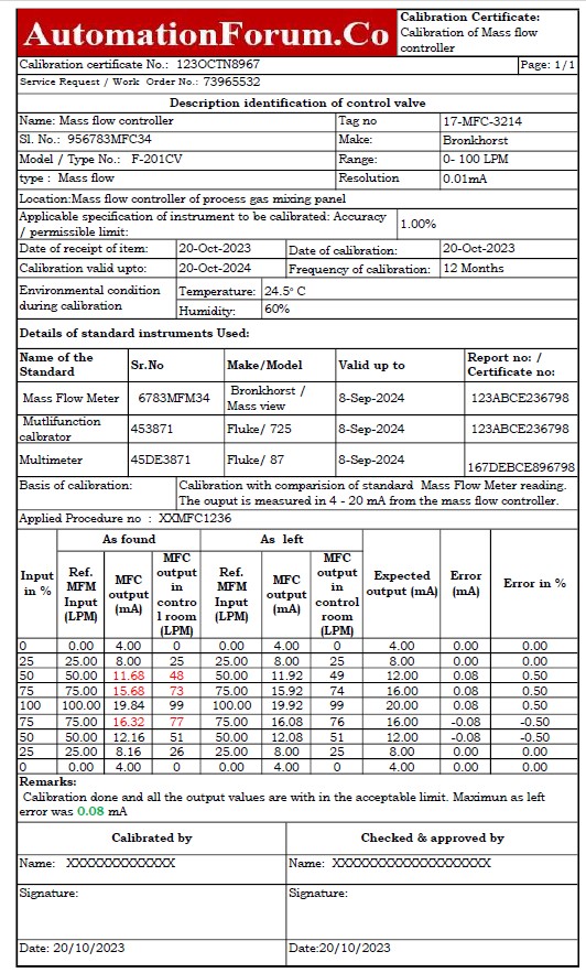
The Excel template that was used to make the mass flow controller calibration report can be downloaded from the link below.
Click here for more about Mass Flow controller
Click here for Troubleshooting of Mass Flow controller
Calibration Standards for Mass Flow Controller
To ensure precise measurements in a range of industrial applications, follow our carefully designed Thermal Mass Flow Controller calibration method, which meets NIST requirements.
When calibrating Thermal Mass Flow Controllers, adhere to recognized standards such as ISO 17025 and ASME MFC-6M for performance criteria, testing methods, and calibration procedures. Additionally, refer to the manufacturer’s documentation for model-specific guidelines and recommendations to achieve accurate and reliable flow measurements.
Click here for more Calibration Procedure