
- Pressure Relief Valve Sizing Calculator for PRV and PSV Orifice Calculation
- What Is a Pressure Relief Valve Sizing Calculator?
- Why Pressure Relief Valve Sizing Is Important
- What Information Is Required for Pressure Relief Valve Sizing?
- How the Pressure Relief Valve Sizing Calculator Works
- Gas and Vapor Pressure Relief Valve Sizing
- Liquid Pressure Relief Valve Sizing
- Steam Pressure Relief Valve Sizing
- How Backpressure Affects Pressure Relief Valve Sizing
- How Critical Flow and Choked Flow Affect PRV Sizing
- Standard API 526 Pressure Relief Valve Orifice Sizes
- Pressure Relief Valve Sizing Calculation Example
- How to Interpret Pressure Relief Valve Sizing Calculator Results
- Important Engineering Checks Before Selecting a PRV
- Common Pressure Relief Valve Sizing Mistakes
- Common Problems When Pressure Relief Valve Sizing Results Look Incorrect
- Pressure Relief Valve Sizing for EPC Projects
- Pressure Relief Valve Sizing Applications in Process Industries
- Pressure Relief Valve Sizing Best Practices
- Frequently Asked Questions About Pressure Relief Valve Sizing
- Conclusion: Pressure Relief Valve Sizing Calculator for Engineering Screening
Pressure Relief Valve Sizing Calculator
Pressure Relief Valve Sizing Flow
1. Service & Process Conditions
2. Fluid Properties
Pressure Relief Valve Sizing Results
Step by Step Calculation
API 526 Orifice Screening
| Parameter | Value |
|---|
API 526 Standard Orifice Reference
Calculation Basis Used In This Tool
The equations above follow the calculation structure presented by the referenced Pressure Relief Valve Sizing calculator. The implementation separates gas/vapor, liquid and steam screening paths and displays the assumptions used for each calculation.
Engineering Checks
Pressure Relief Valve Sizing Calculator for PRV and PSV Orifice Calculation
Pressure relief valve sizing is a critical engineering activity in process plants because the relief device must safely handle the required relief load during an overpressure scenario. Proper sizing requires more than checking set pressure or valve connection size. Relief load, relieving pressure, temperature, fluid properties, backpressure, discharge coefficient, and required orifice area must all be considered.
This Pressure Relief Valve Sizing Calculator provides a practical engineering screening method for gas or vapor, liquid, and steam services. It calculates the required relief orifice area and compares the result with standard API 526 orifice sizes.
The calculator can be used for process design, EPC engineering, design review, commissioning preparation and preliminary PRV or PSV selection. The final valve selection is determined by applicable standards, certified manufacturer data, project requirements, and engineering assessment.
What Is a Pressure Relief Valve Sizing Calculator?
What Does a PRV Sizing Calculator Calculate?
A pressure relief valve sizing calculator determines the required effective discharge area needed for a pressure relief valve to discharge the required relief load under specified relieving conditions.
What Does a PSV Sizing Calculator Calculate?
The attached calculator provides three calculation paths:
- Gas or vapor
- Liquid
- Steam
It accepts process conditions such as set pressure, overpressure, backpressure, atmospheric pressure, flow rate, temperature, molecular weight, specific heat ratio, compressibility factor, discharge coefficient, and other correction factors.
The calculated area is then compared with the standard orifice areas represented in the calculator.
Calculate accurate Cv values before selecting control valves: Control Valve Sizing Calculator: Complete ISA S75.01 Cv Calculation Guide for Instrumentation Engineers
Why Pressure Relief Valve Sizing Is Important
- An undersized pressure relief valve may not discharge the required relief load. This can allow pressure to continue increasing in protected equipment.
- Oversizing also requires engineering attention because unsuitable valve capacity and operating conditions can contribute to unstable operation or cycling.
- During relief system design, the engineer should first establish the governing relief scenario. Typical scenarios can include blocked outlet, control valve failure, cooling failure, external fire, thermal expansion, tube rupture, utility failure, pump deadhead, compressor pressure increase, or steam system overpressure.
- The calculator does not determine the relief scenario or relief load. The engineer must establish these values before performing the sizing calculation.
Refer the below link for the Understanding Rangeability vs Turndown Ratio in Control Valve Sizing
What Information Is Required for Pressure Relief Valve Sizing?
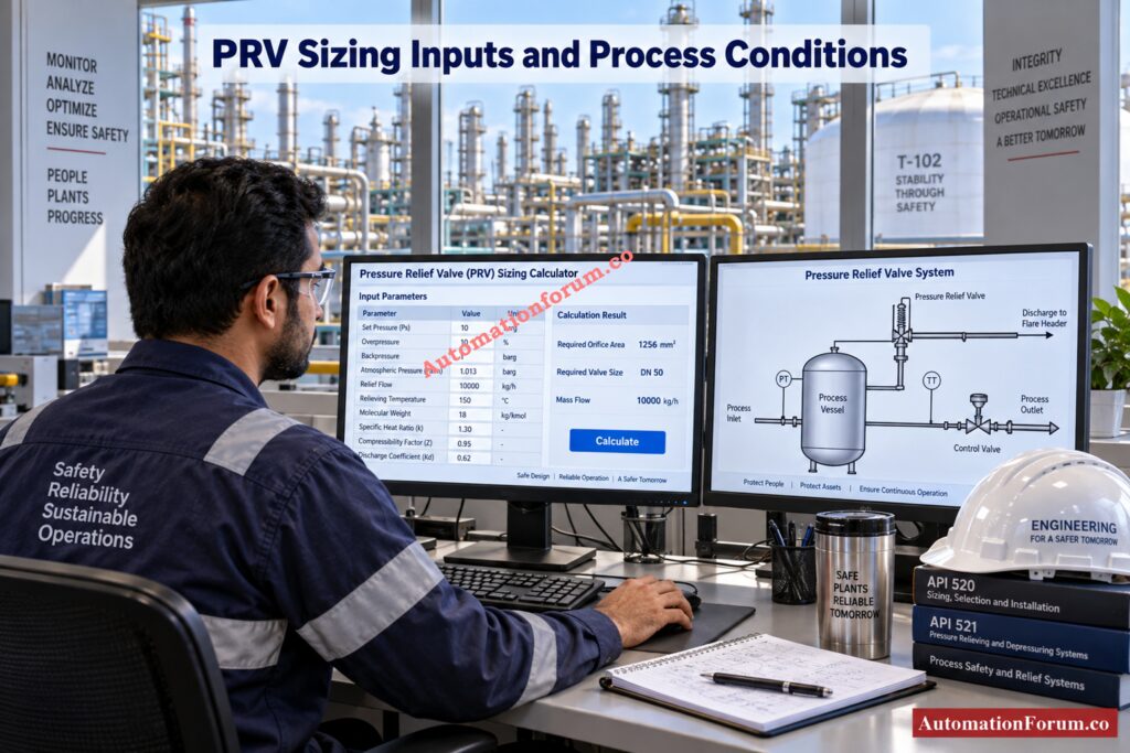
- The calculator needs different information for each service.
- For gas or vapor service, important inputs include relief mass flow, set pressure, overpressure, backpressure, atmospheric pressure, molecular weight, relieving temperature, specific heat ratio, compressibility factor, discharge coefficient, backpressure factor, and combination factor.
- For liquid service, the calculator additionally uses liquid flow, specific gravity, viscosity, and liquid discharge coefficient.
- For steam service, the calculator uses the steam relief flow and pressure conditions together with the correction structure incorporated into the tool.
Solve critical flow sizing problems with practical engineering tools: Control Valve Sizing Calculation Worksheet for Critical and Sub-Critical Flow: Excel Tool
How the Pressure Relief Valve Sizing Calculator Works
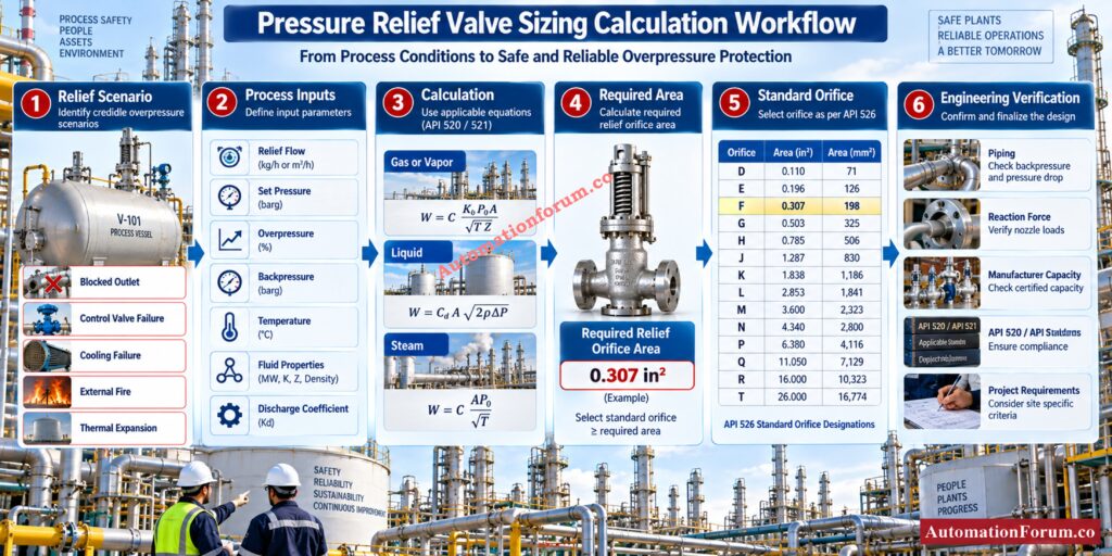
The calculation begins by converting the entered gauge pressures into absolute pressures.
The calculator uses:
P1 = Pset × (1 + Overpressure / 100) + Patm
Here, P1 is the absolute relieving pressure.
Backpressure is converted using:
P2 = Pback + Patm
The pressure ratio is then:
r = P2 / P1
Using absolute pressure is important because compressible fluid relief calculations depend on the absolute pressure relationship across the relief device. This conversion is explicitly done by the calculator before computing the area needed.
Verify valve Cv before making critical sizing decisions: Why Measuring Control Valve Cv is Essential for Proper Valve Sizing ?
Gas and Vapor Pressure Relief Valve Sizing
For gas or vapor service, the calculator evaluates if the flow is critical or subcritical by comparing the actual pressure ratio to the critical pressure ratio.
The critical pressure ratio is calculated as:
rCF = (2 / (k + 1)) ^ (k / (k − 1))
The gas expansion coefficient is calculated as:
C = 520 × √[k × (2 / (k + 1)) ^ ((k + 1) / (k − 1))]
The required orifice area is then calculated using:
A = W / (C × Kd × P1 × Kb × Kc) × √(T × Z / M)
where W is the needed mass flow; Kd is the discharge coefficient; Kb is the backpressure factor; Kc is the combination factor; T is the absolute temperature; Z is the compressibility and M is the molecular weight. These variables are directly represented in the calculator.
When the pressure ratio is below the calculated critical ratio, the calculator identifies the condition as critical or choked flow. Otherwise, it identifies the condition as subcritical flow.
Convert gas valve coefficients accurately for better sizing: Cv to Cg for Gases Conversion Calculator: Control Valve Sizing
Liquid Pressure Relief Valve Sizing
Liquid relief sizing follows a different calculation path because liquid flow behaviour differs from compressible gas flow.
The calculator first determines the pressure differential:
ΔP = P1 − P2
The uncorrected area is calculated as:
Au = Q / (38 × Kd × Kb × Kc) × √(G / ΔP)
The calculator then determines Reynolds number:
Re = Q × 2800 × G / (μ × √Au)
The viscosity correction factor is:
Kv = [0.9935 + 2.878 / √Re + 342.75 / Re^1.5]⁻¹
The final corrected area becomes:
A = Au / Kv
This correction is important because liquid viscosity affects the flow behaviour through the relief valve. A higher viscosity can increase the required effective area. The calculator therefore should not be treated as a simple pressure differential calculation for liquid services.
Size liquid control valves faster without repeated calculations: Control Valve Sizing Excel tool Without Iteration: Liquid Application
Steam Pressure Relief Valve Sizing
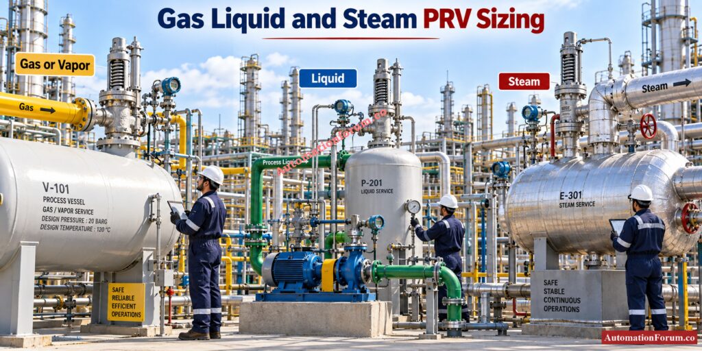
Steam uses a separate calculation structure in the calculator.
The tool uses a Napier style relationship based on the entered relieving pressure, relief flow, discharge coefficient, backpressure factor, combination factor, superheat correction, and high pressure factor.
The calculator currently represents:
Ksh = 1
KN = 1
The resulting area is calculated using the steam relationship incorporated into the tool.
For actual steam PSV selection, engineers should verify the required correction factors against the applicable current standard and certified manufacturer information rather than assuming the screening values are suitable for every service.
Refer the below link for the Top 10 Control Valve Sizing Software Used in Process Industries
How Backpressure Affects Pressure Relief Valve Sizing
- Backpressure is the pressure acting at the valve outlet. It can influence the flow capacity and therefore the required relief area.
- The calculator converts backpressure into absolute pressure and uses it to establish the pressure ratio. It also provides a backpressure factor input called Kb.
- Valve type is important because conventional, balanced bellows, and pilot operated valves have different application limitations. The calculator therefore allows the engineer to identify the valve type before evaluating the result.
- During a design review, backpressure should be checked against the complete discharge system rather than considering only the nominal outlet pressure.
Calculate gas PSV capacity before final relief valve selection: Pressure Safety Valve Sizing Excel Tool for Gas Applications
How Critical Flow and Choked Flow Affect PRV Sizing
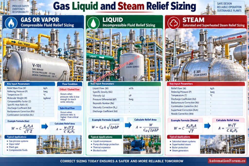
- Critical flow occurs when the downstream pressure is sufficiently low compared with the upstream relieving pressure for the flow to reach the critical condition.
- Under this condition, reducing downstream pressure further does not increase the mass flow through the restriction in the same manner as subcritical flow.
- The calculator calculates the critical pressure ratio and compares it with the actual pressure ratio. This determines whether the displayed gas result is classified as critical or choked flow or subcritical flow.
Calculate pneumatic valve air demand before system design: Air Consumption Calculator for Pneumatic Control Valves, Actuators and Instrument Air System Sizing
Standard API 526 Pressure Relief Valve Orifice Sizes
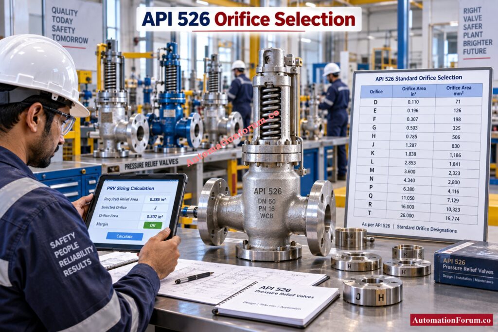
After calculating the required area, the calculator compares it with the standard orifice areas included in the tool.
The represented API 526 series is:
| Orifice | Area in square inches |
| D | 0.110 |
| E | 0.196 |
| F | 0.307 |
| G | 0.503 |
| H | 0.785 |
| J | 1.287 |
| K | 1.838 |
| L | 2.853 |
| M | 3.600 |
| N | 4.340 |
| P | 6.380 |
| Q | 11.050 |
| R | 16.000 |
| T | 26.000 |
The calculator selects the first listed standard orifice having an area equal to or greater than the calculated requirement.
This is an initial orifice screening function. Final valve selection must also consider certified valve capacity, manufacturer data, installation conditions, applicable standards, and project specifications.
Prevent compressor surge with properly sized anti surge valves: Anti-Surge Control Valve Selection and Sizing – Complete Engineering Guide
Pressure Relief Valve Sizing Calculation Example
Consider a gas service with the following calculator inputs:
- Set pressure: 100 psig
- Overpressure: 10 percent
- Backpressure: 5 psig
- Atmospheric pressure: 14.7 psia
- Relief flow: 50,000 lb/hr
- Molecular weight: 16.04
- Relieving temperature: 150°F
- Specific heat ratio: 1.31
- Compressibility factor: 1
- Discharge coefficient: 0.975
- Backpressure factor: 1
- Combination factor: 1
The relieving pressure becomes:
P1 = 100 × 1.10 + 14.7 = 124.7 psia
The absolute backpressure becomes:
P2 = 5 + 14.7 = 19.7 psia
Therefore:
r = 19.7 / 124.7 = approximately 0.158
The calculator identifies this as a critical or choked gas flow condition for the entered gas properties.
Using the calculator methodology, the required area is approximately 7.41 square inches. The next available standard orifice in the calculator is Q, with an area of 11.05 square inches.
This result is a screening result. An engineer should not issue the final PSV specification from this calculation alone.
Calculate actuator torque before valve selection goes wrong: Valve Actuator Sizing Calculator – Complete Engineering Guide
How to Interpret Pressure Relief Valve Sizing Calculator Results
The result provides several useful engineering outputs:
- Required relief orifice area
- Relieving pressure
- Backpressure
- Flow regime
- Reaction force
- Selected standard orifice
The calculator also displays the calculation steps so an engineer can review the intermediate values rather than relying only on the final area.
Detect cavitation risks before they damage your control valve: Control Valve Cavitation Calculator
Important Engineering Checks Before Selecting a PRV
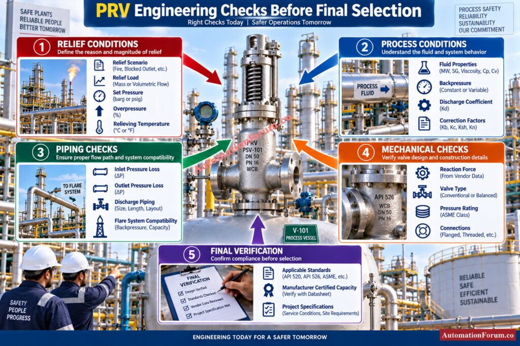
Before accepting a calculated area, verify the following:
- Correct governing relief scenario
- Required relief load
- Set pressure
- Allowable overpressure
- Relieving temperature
- Relieving pressure
- Backpressure
- Fluid properties
- Discharge coefficient
- Correction factors
- Inlet pressure loss
- Outlet pressure loss
- Reaction force
- Discharge piping
- Flare system compatibility
- Applicable codes and standards
- Manufacturer certified capacity
- Project specifications
The calculated required area is only one part of PRV engineering. Sizing, valve selection, valve specification, installation, and certification are separate engineering activities.
Calculate valve leakage accurately before accepting shutdown performance: Control Valve Leakage Calculator
Common Pressure Relief Valve Sizing Mistakes
- Using Gauge Pressure Directly: Forcompressible flow calculations, you must use absolute pressure. Know the ambient pressure. Convert gage pressure. Compute.
- Entering the Wrong Relief Load: The corresponding relief load must be for the controlling situation. A technically sound computation with a wrong relief load nonetheless gives a wrong result.
- Ignoring Backpressure: Inspect all of the discharge path including headers, pipes, fittings and flare systems as applicable.
- Using Incorrect Fluid Properties: The molecular weight, specific heat ratio, compressibility, specific gravity and viscosity should be representative of the actual relieving circumstances.
- Misinterpreting the API 526 Orifice: The selected letter is a consequence of screening from the standard areas indicated in the calculator. It is not a valve specification in itself and comprehensive.
Select control valves confidently for severe process conditions: Control Valve Selection and Recommended Practices for Harsh Process Conditions
Common Problems When Pressure Relief Valve Sizing Results Look Incorrect
If the area computed is too large or too tiny, examine the input data first.
Check the flow units, pressure units, atmospheric pressure, relieving temperature, molecular weight, specific heat ratio, compressibility factor, set pressure, overpressure and backpressure.
Check liquid specific gravity, viscosity, liquid flow and liquid discharge coefficient specifically for liquid service.
Also confirm that the selected relief scenario actually produces the entered relief load. During commissioning or troubleshooting, comparing the calculator inputs with the approved process datasheet and relief study is often the fastest way to identify an incorrect result.
Pressure Relief Valve Sizing for EPC Projects
- In an EPC project, PRV sizing normally begins with the process relief scenario and required relief load. The resulting sizing calculation supports the valve datasheet and equipment specification.
- Valve selection then considers the valve type, certified coefficients, backpressure limitations, materials, temperature range, pressure rating, inlet and outlet connections, discharge arrangement, and project specifications.
- A conventional valve, balanced bellows valve, and pilot operated valve should not be treated as interchangeable simply because their calculated areas appear similar.
Identify control valve failure modes before plant problems escalate: What Are the Most Common Failure Modes of Control Valves?
Pressure Relief Valve Sizing Applications in Process Industries
- Pressure relief valve sizing is important for process vessels, separators, reactors, heat exchangers, compressors, pumps, storage vessels, refinery systems, petrochemical units, chemical plants, gas processing systems, steam systems, and hydrocarbon facilities.
- During a plant design review, engineers may encounter relief scenarios such as blocked outlet, control valve failure, external fire, cooling failure, thermal expansion, tube rupture, utility failure, pump deadhead, or compressor pressure increase.
- Each scenario requires an appropriate engineering assessment before the relief load is entered into the sizing calculator.
Stop closed valves from passing and causing process problems: Control Valve Passing Even When Fully Closed: Causes, Symptoms, Troubleshooting and Solutions
Pressure Relief Valve Sizing Best Practices
- Start with the governing relief scenario.
- Use the actual required relief load.
- Convert pressure values correctly.
- Use relieving temperature and fluid properties.
- Backpressure read attentively.
- Apply relevant correction and discharge factors.
- Compare the computed area with the corresponding standard orifice sizes.
- Check discharge and inlet pipes.
- Verify reaction forces.
- Confirm manufacturer certified capacity.
- Complete the final design using the applicable current standards and project requirements.
Check liquid relief capacity before final safety valve selection: Pressure Safety Relief Valve Basic Sizing Tool – Liquid Applications
Frequently Asked Questions About Pressure Relief Valve Sizing
How do I calculate the PRV sizing of a valve?
The PRV sizing determination of the needed discharge area is based on relief flow, relieving pressure, temperature, fluid characteristics, and correction variables.
Then the final area is compared with an appropriate standard orifice size for the selected pressure relief valve.
How do I calculate the size of a relief valve?
Determine the required relief area by applying the appropriate gas, liquid, or steam sizing method and the controlling relief scenario.
Compare the computed area to the standard orifice and then check the valve capacity against manufacturer data.
What is the 3% rule for pressure relief valves?
The 3% rule generally means minimizing the pressure loss in the PRV input piping to about 3% of set pressure.
This check reduces the danger of unstable valve operation and should be checked against the applicable standard and project criteria.
How to size a PRV valve?
To size a PRV, find the relieving load necessary, set pressure, overpressure, relieving temperature, backpressure, and fluid characteristics.
Calculate needed area using appropriate sizing equation, confirm orifice size, valve type, piping and verified capacity.
Prepare accurate valve datasheets without missing critical details: How to Prepare Control Valve Datasheets: A Step-by-Step Procedure for EPC Instrumentation Engineers
How do you size a PSV?
Sizing the PSV requires the controlling overpressure situation, needed relief load, relieving conditions, fluid parameters, and applicable correction factors.
The computed discharge area is then utilized for preliminary orifice selection and final verification against approved manufacturer data.
What is pressure relief valve sizing?
Sizing a pressure relief valve involves determining the discharge area required to properly pass the requisite relief load during an overpressure event.
It is calculated as a function of the fluid service, the relieving conditions, the valve coefficients and applicable technical criteria.
What is the difference between PRV and PSV sizing?
Sizing of both PRV and PSV determines the required relieving capacity and discharge area to protect pressurized equipment.
Terminology varies by industry, application and engineering criteria.
Why is absolute pressure used in PRV sizing?
Absolute pressure is important because gas and vapor sizing calculations depend on the pressure ratio between upstream and downstream conditions.
Using gauge pressure directly can produce an incorrect relieving pressure and therefore an incorrect required orifice area.
Master leakage testing requirements before approving control valves: Control Valve Leakage Testing, Types, and Calculation Standards
How is required relief valve area calculated?
Required relief area is calculated using service specific equations for gas or vapor, liquid, or steam conditions.
The calculator applies flow rate, pressure, temperature, fluid properties, discharge coefficients, and relevant correction factors.
What is critical flow in a pressure relief valve?
Critical flow occurs when the downstream pressure is sufficiently low compared with the relieving pressure for the flow to reach the critical condition.
The calculator identifies critical or choked flow by comparing the actual pressure ratio with the calculated critical pressure ratio.
How does backpressure affect relief valve sizing?
Capacity correction may be required for the effect of backpressure on pressure difference and flow behavior via the pressure relief valve.
The effect is dependent on the type of valve, the discharge conditions and the relevant correction factor.
How is an API 526 orifice selected?
The calculated required relief area is compared with the standard API 526 orifice areas represented in the calculator.
The calculator identifies the first listed orifice having an area equal to or greater than the calculated requirement.
Why is liquid viscosity important?
Liquid viscosity influences both the Reynolds number and the viscosity correction factor used in liquid relief valve sizing.
The higher viscosity can affect the flow behavior and raise the corrected needed discharge area.
What information is required before sizing a pressure relief valve?
The engineer needs the governing relief scenario. Required relief load. Set pressure. Overpressure. Temperature. Backpressure. Fluid characteristics.
Valve coefficients, correction factors, piping conditions, applicable standards, and manufacturer data are also required for final selection.
Conclusion: Pressure Relief Valve Sizing Calculator for Engineering Screening
A Pressure Relief Valve Sizing Calculator can significantly simplify preliminary PRV and PSV orifice calculations when the engineering inputs are properly established. The attached calculator provides separate calculation paths for gas or vapor, liquid, and steam services and performs initial API 526 orifice screening.
For instrumentation, process, EPC, commissioning, and maintenance engineers, the important point is that the calculated orifice area is not the entire relief system design. The governing relief scenario, relief load, relieving conditions, backpressure, piping, valve type, certified capacity, applicable standards, and manufacturer data must all be reviewed before final selection.
The calculator should therefore be used as a practical engineering screening and verification tool, followed by formal PRV or PSV sizing and certification using the applicable current requirements. The calculation structure and limitations are explicitly identified in the attached calculator.
Restore stuck control valves before they disrupt production: How to do maintenance on struck control valve?
