This design guide aims to help readers understand the basic concepts behind the design and sizing of pressure relief valves for liquid flow. Pressure safety valves are critical for process safety, often serving as the last line of defense against explosions. Therefore, their design should be entrusted to reputable companies. The valve supplier must be consulted to clearly define the application, valve position, and other relevant factors. This collaboration allows the supplier to advise the plant operator properly and finalize the valve design.
This guide does not cover the selection and calculation of the design scenario, which involves identifying the process events that lead to the maximum flow released through the valve. Determining the required flow involves conducting a risk analysis and process calculations.
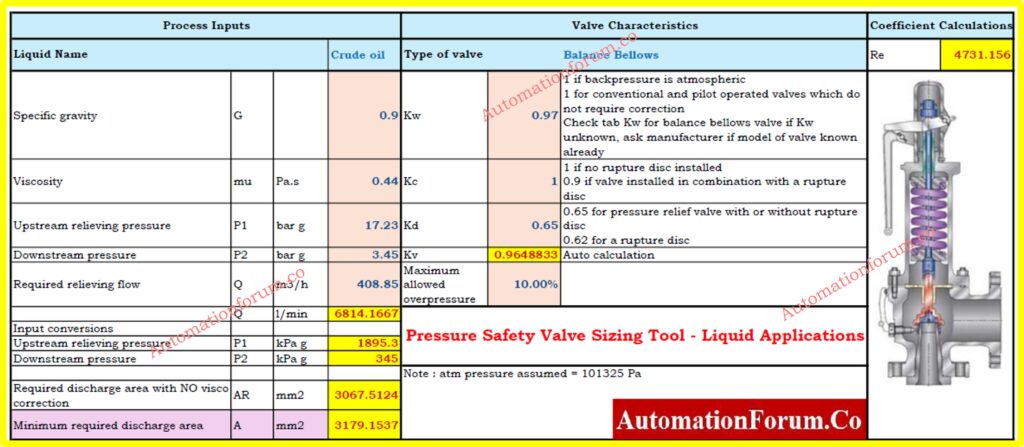
Safety Valve Sizing – Liquid Service
For liquid applications, the following formula can be used to size a pressure safety valve. Warning: This formula is not valid for gases. For gas applications, please refer to the appropriate guidelines.
The calculations provided here are derived from API520 and adapted from various sources, specifically for liquid applications. Different services, such as gas or low-pressure/vacuum valves, require different calculation codes. For example, API has separate standards for gas service, while ASME and ISO have their own guidelines.
Formula and Calculation for Pressure Safety Valve (Liquid)
For liquid applications, the following formula can be used to size a pressure safety valve. Warning: This formula is not valid for gases. For gas applications, please refer to the appropriate guidelines.
Click here for Pressure Safety Valve Sizing Excel Tool for Gas Applications
Equation for calculating Required Discharge Area
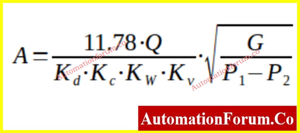
Where:
- P1 = Upstream relieving pressure in kPa g (set pressure + allowable overpressure)
- P2 = Backpressure in kPa g
- A = Required effective discharge area of the safety valve in mm²
- Q = Required flow through the valve in l/min
- G = Specific gravity of the liquid (water under ordinary conditions) at the flowing temperature
- Kd = Coefficient of discharge. Typically, manufacturer data should be used, but for a first approximation:
- Kd = 0.65 for a pressure relief valve, with or without a rupture disc upstream
- Kd = 0.62 for a rupture disc
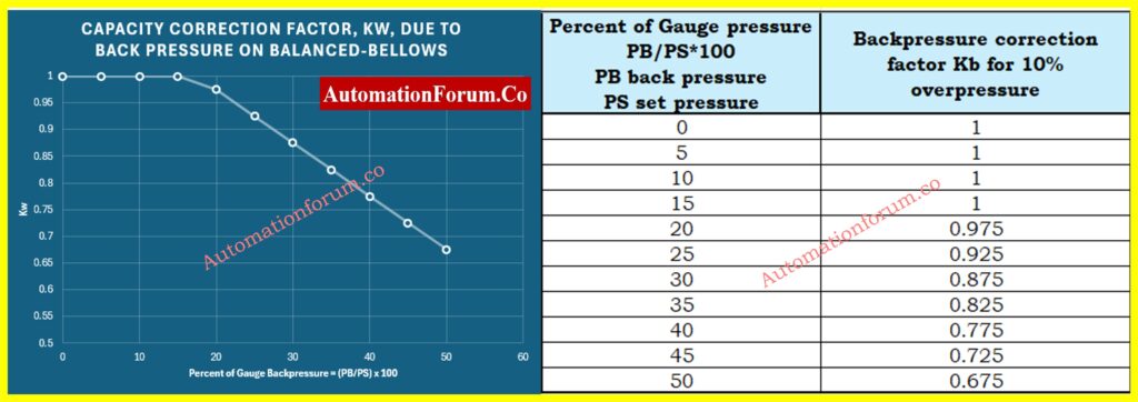
- Kw = Capacity correction factor due to back pressure:
- Kw = 1 for atmospheric back pressure
- Kw is not used for conventional and pilot-operated valves (no correction required)
- Kw should be estimated from tables and charts for balance bellow valves (see figure 1)
- Kc = Compensation factor in the event that the valve is inserted before a rupture disc:
- Kc = 1 when no rupture disc is installed
- Kc = 0.9 if a rupture disc is used with the valve
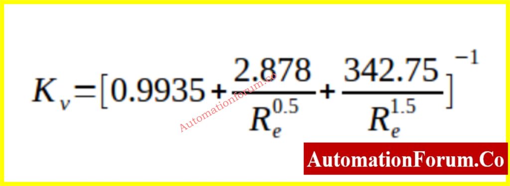
- Kv = Correction factor due to viscosity
- T = Temperature of the gas or vapor upstream the valve at the moment it is released in K
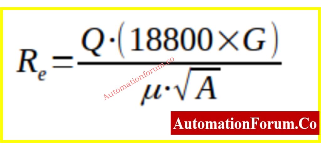
- Re = Reynolds number
- ? = Fluid viscosity in cP
The coefficient Kw, which adjusts for back pressure on balanced bellow safety valves, can be determined using the following graphical representation
The capacity correction factor Kw, which accounts for back pressure on balanced-bellows safety valves
The coefficient Kv can be calculated using the following formula:
The Reynolds number (Re) for a pressure safety valve in liquid service can be calculated using the following equation:
ISO 4126: Standard for Safety Valve Sizing
ISO 4126 is an internationally recognized standard that provides comprehensive guidelines and correlations for the sizing of safety valves. It offers methodologies and formulas that ensure safety valves are properly sized and selected based on various parameters such as fluid type, pressure, temperature, and flow characteristics. Adhering to ISO 4126 helps ensure consistency and reliability in the design and implementation of safety valves, contributing to the overall safety and efficiency of industrial processes and systems.
Selection of Standard Relief Valves Orifice
The sizes of discharge areas for standard relief valves are standardized, and manufacturers typically propose sizes based on these standards. After calculating the required size using the sequence outlined above, engineers need to select a standard size that provides a discharge area greater than the calculated value.
The below table is presenting the standard letter/designation and the corresponding orifice area in both square inches and square centimeters:
| Standard Letter/Designation | Orifice Area (in²) | Orifice Area (cm²) |
| D | 0.110 | 0.71 |
| E | 0.196 | 1.26 |
| F | 0.307 | 1.98 |
| G | 0.503 | 3.24 |
| H | 0.785 | 5.06 |
| J | 1.28 | 8.30 |
| K | 1.84 | 11.85 |
| L | 2.85 | 18.40 |
| M | 3.600 | 23.23 |
| N | 4.340 | 28.00 |
| P | 6.38 | 41.16 |
| Q | 11.050 | 71.29 |
| R | 16 | 103.22 |
| T | 26 | 167.74 |
These standard designations provide a range of orifice areas that can be selected based on the calculated requirements for liquid flow under pressure.
Excel Calculation Tool for Safety Relief Valve Sizing
This Excel tool supports calculations for liquid flow under pressure. For gas service, please refer to the specific guidelines and tools designed for gas flow calculations.
Refer below link to download Excel Calculation Tool for Safety Relief Valve Sizing in Liquid service
This guide is not intended for designing valves for operational purposes. The guide is based on published sources and should not be used for the detailed design, selection, or ordering of a pressure safety valve.
Click here for more excel Instrumentation tools