- What is a Gas Metering System?
- Gas Metering System in Custody Transfer
- Major Components of a Gas Metering System
- Ultrasonic Flow Meter
- Gas Chromatograph (GC)
- Flow Computer
- Function of Flow Calculators
- Gas Metering Station Components
- Selection Criteria for Gas Metering Devices
- International Standards for Gas Metering Systems
- Types of Gas Flow Measurement Methods
- Frequently Asked Questions
What is a Gas Metering System?
A gas metering system is a specialized measurement system used to determine the quantity and energy content of natural gas during custody transfer transactions. Custody transfer occurs when gas ownership is transferred from one party to another, such as from a gas production facility to a pipeline operator or end user.
Because the gas is sold based on measured volume and energy content, measurement accuracy is extremely critical for both buyer and seller. Even small measurement errors can lead to significant financial losses in large-scale gas trading.
A custody transfer gas metering system typically consists of several integrated components including:
- Flow measurement devices
- Pressure and temperature transmitters
- Gas chromatographs
- Flow computers
- Data acquisition and control systems
Together, these devices ensure accurate gas quantity and energy measurement before the gas is transferred to the customer.

Gas Metering System in Custody Transfer
In the oil and gas industry, the custody transfer metering station represents the final measurement point before gas is delivered to another operator or customer.
Instead of relying on a single flow meter, custody transfer requires a complete metering system designed to meet strict accuracy and regulatory requirements.
The system generally includes:
- Metering skid
- Analyzer shelter
- Flow computer system
- Control and monitoring panels
The measurement uncertainty for custody transfer gas metering is typically required to be within ±1% or better, depending on contract agreements and industry standards.
Major Components of a Gas Metering System
- The gas metering system is defined as a supervision transfer, which occurs when fluid or gas is measured for sale from one party to another.
- When transferring a material, accuracy is extremely essential for both the company, & recipient during material delivery.
- A custody transfer meter (CTM) is a meter that is designed, installed, and operated to meet the requirements for custody transfer measurement.
- Custody transfer necessitates an entire metering system, not just flow meters, that is designed and engineered for measuring the product gas application.
- The custody transfer metering skid is a piping system supported by a structural base.
- It houses all primary measurement instruments, such as ultrasonic flow meters, pressure transmitters, temperature transmitters, and MOVs, as well as straight lengths as specified by AGA 9(American Gas Association).
- Flow profiler, piping, and structural design, fabrication, and testing adhere to project specifications as well as applicable codes and standards while keeping functional requirements in mind.
- The analyzers analyze gas components and provide data to flow computers for energy calculation.
- The analyzer house is designed to be located in the hazardous zone of Zonal Gr-HB T3 and includes HVAC units, fire and gas sensors, and a safety PLC.
- To ensure representative samples, sample probes (installed on the metering skid) and an analyzer sample handling system are provided.
- The metering cabinets are housed in a secure area of the control room.
- The Human Machine Interface (HMI), also known as the metering station computer, makes it possible to keep track of all the information concerning the measured quantity and quality of the gas that is being exported.
- This computer serves as the interface between all instrumentation and the operator. The operator can review the history, print the report, and diagnose the flowmeter, among other things.
- It also serves as an interface between the gas metering system and other control systems at the plant, such as the PCS (Process Control System), ESD (Emergency Shutdown) system, and so on.
- The flow computers, station computers, GC controllers, PLC, HMI, and Ethernet switches with DCS interface are all housed in the panel.
- All flow and energy calculations are performed by flow computers, which collect data from skids and analyzer houses.
- The station computers compile and generate reports based on the station values.
- A Gas Metering System (also known as a CTM) typically includes the following components:
Ultrasonic Flow Meter
- Two ultrasonic transducers installed at an angle to the gas flow act alternately as a transmitter and receiver.

An ultrasonic flow meter is widely used in modern natural gas custody transfer systems due to its high accuracy and reliability.
It works based on the transit time principle, where ultrasonic signals are transmitted both upstream and downstream through the gas flow.
Two ultrasonic transducers alternately act as transmitters and receivers.
Key principle:
- Sound waves traveling with the flow arrive faster
- Sound waves traveling against the flow arrive slower
The difference in transit time is used to calculate the gas velocity and volumetric flow rate.
Advantages of ultrasonic flow meters:
- High accuracy (up to ±1%)
- No moving parts
- Minimal pressure drop
- Wide flow range
- Low maintenance requirements
Multi-path ultrasonic meters measure velocity across several paths inside the pipe, improving measurement accuracy and flow profile detection.
Gas Chromatograph (GC)
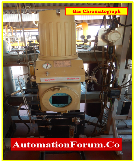
- Gas chromatographs (GC) are used throughout natural gas pipeline networks to analyze the flowing gas and calculate the physical properties used for flow calculations and custody transfer.
- A gas chromatograph (GC) is an analytical instrument to calculate the concentration of the sample.

- The sample solution injected into the instrument is carried by a gas stream into a separation tube known as the “column.” (As the so-called carrier gas, helium or nitrogen is used.)
- Within the column, the various components are separated.
- The detector counts the number of components that exit the column. A known concentration standard sample is injected into the instrument to measure a sample with an unknown concentration.
- The quality of the gas is determined by its composition and characteristics.
- The gas composition will be measured using a gas chromatograph and provided as a percentage composition. For example, for a specific measurement, CH4 (methane) composition is 98%, C2H6 (ethane) composition is 0.05%, and so on.
- This composition data will be input into the flow computer, which will calculate the Gross Heating Value (GHV).
Flow Computer
- The Flow computer was created specifically for measuring hydrocarbon liquids and gases where versatility and accuracy are critical.

- The flow computer enables the configuration of multi-stream, multi-station applications for the simultaneous metering of liquids and gases.
- The flow computer’s primary function is to collect gas flow data from connectors at meter runs, meters, or transmitters and calculate volumetric flow rate and energy flow under reference conditions.
- Flows are computed on an hourly, daily, and overall basis.
- Flow computers generate real billing data, which is stored and processed.
- The volume of gas consumed is calculated independently for each meter by the flow calculator.
- Flow calculators are intended to calculate the flow of energy and gas volume while considering the signals from the respective meter run metering device, temperature, pressure, and the overall chemical analysis using gas chromatographs.
Function of Flow Calculators
- Calculate the gas volume (m) and flow rate (m/h) at the meter’s operating pressure and temperature.
- Apply the error correction equation for the respective meter (ultrasonic flow meters) to the meter run pressure and temperature to calculate the gas volume (m) and volume flow rate (m/h).
- Under normal pressure and temperature conditions, compute the gas volume (Nm) and volume flow rate (m/h) (reference conditions).
- Calculate the gas compressibility for the meter run temperature and pressure conditions, as well as the chromatograph composition.
- Using the calculated Gross Calorific Value and volume of the gas, calculate the energy of the passing gas (MJ) and the energy flow rate (MJ/h).
Energy Contents of Gas
- The calorific value (CV) of a standard volume of gas is generally measured in units of MJ/SCM.
- The CV is a measure of the amount of heat generated by the combustion of a standard cubic meter of gas, and it is measured under contractual conditions (pressure and temperature)
- CV is determined by gas composition, which can be measured directly with a calorimeter or calculated from gas compositional analysis measured with an online gas chromatograph.
Gas Energy Measurement Concept
- The flowmeter measures the actual volume of gas under actual conditions (pressure and temperature measured in Actual Cubic Meters) (ACM)
- To calculate the amount of energy contained in this volume, it must first be converted to standard volume, which is measured in Standard Cubic Meters (SCM)
SCM = Standard Cubic Meter to standard temperature and pressure conditions 15 Degrees Celsius and 1 Bar.
Vstd = Vact * (Pact / Pstd) * (Tstd / Tact)
Where
- Vstd = is the Volume at standard conditions
- Vact = is the Volume at actual conditions
- Pstd = is the Pressure at standard conditions
- Pact = is the Pressure at actual conditions
- Tstd = is the Temperature at standard conditions
- Tact = is the Temperature at actual conditions
Since Natural Gas is not Ideal gas, compressibility (Z) adjustment must be considered
E = Vstd *Z * CV
E is Energy Billing Quantity, Z is being calculated using AGA report no.VIII
In the event that the gas flow meter is measuring mass flow
E = M / (Sp.G x ?) x C.V
- M is the mass of gas delivered.
- Sp. G is the specific gravity (or relative density) of dry gas to dry air at standard conditions.
- ? is the density of dry air at standard conditions.
Gas Metering Station Components

- A metering station would typically have several metering “streams” to provide redundancy and cross-checking.
- Each stream must include the following components for energy measurements.
- The flow will be measured by the primary device, while the field instruments or analyzers will send the measured values to the gas flow computer.

The gas flow computer will perform the following functions
- Determine the mass and volumetric flow rates.
- Conformity of density and temperature – measured downstream of the primary device – to the contractual conditions upstream
- If no density is measured, density is calculated from gas composition using AGA report no. VIII.
- Determine the calorific value based on the gas composition.
Selection Criteria for Gas Metering Devices
When selecting a primary metering device, engineers must consider several technical and contractual factors.
Key selection considerations include:
- Measurement accuracy requirements
- Flow range and turndown ratio
- Gas composition and quality
- Installation space availability
- Maintenance and calibration requirements
- Initial installation cost
International Standards for Gas Metering Systems
Gas metering systems must comply with international measurement standards to ensure accuracy and traceability.
Common standards used in natural gas metering include:
Orifice Meter Standards
- ISO 5167-1
- AGA Report No.3
Ultrasonic Meter Standards
- BS 7965
- BS ISO/TR 12765
- AGA Report No.9
Turbine Meter Standards
- ISO 9951
- AGA Report No.7
Coriolis Meters
BS ISO 10790
Calculation of CV, Density, and Relative Density
ISO 6976
Gas Chromatograph
- ISO 6974
- ISO 6975
- ASTM – D 1945
Gas Composition and Calorific Value
ISO 6976
ISO 6974
ASTM D1945
Compressibility Calculations
- ISO 12213
- AGA Report No.8
Types of Gas Flow Measurement Methods
Gas flow measurement systems generally fall into four main categories.
Differential Pressure Flow Meters
Examples include orifice plates and venturi meters.
Velocity Flow Meters
Examples include ultrasonic and turbine meters.
Mass Flow Meters
Examples include Coriolis flow meters.
Positive Displacement Flow Meters
Used in smaller industrial and commercial applications.
Frequently Asked Questions
What is the purpose of a gas metering system?
A gas metering system measures the volume and energy content of gas during custody transfer, ensuring accurate billing between gas producers, transporters, and consumers.
What is custody transfer in gas measurement?
Custody transfer refers to the commercial transfer of gas ownership, where the gas quantity must be measured accurately for billing purposes.
Why is gas composition important in metering?
Gas composition determines the calorific value and energy content of natural gas, which is required to calculate the correct billing energy.
What is the most common meter used in natural gas custody transfer?
Multipath ultrasonic flow meters are commonly used due to their high accuracy, low pressure drop, and wide measurement range.
What is the meaning of Gas Metering?
- An instrument to record the quantity of gas passing through a particular outlet.
- A gas metering system is a device that measures the quantity of any gas or the energy content of any gas, either directly or indirectly.
What is a Gas Metering System?
- The gas metering system is defined as a Custody transfer, which occurs when fluid or gas is measured for sale from one party to another.
- Accuracy is essential during material transfer between the company and the recipient.
Why do we need metering?
Metering and monitoring systems are critical components of good facility management. These systems provide valuable insight into facility and equipment performance and support better energy use and cost management, as well as improved system feedback and optimization.
What are the different types of gas metering?
There are four different types of gas metering.
- Mass Flow Meters,
- Velocity Flow Meters,
- Differential Pressure,
- PD Meters