⚙️ Valve Actuator Sizing Calculator
Professional Torque, Safety Factor & Gear Ratio Analysis for EPC Engineers
Following ISO 9359 & NORSOK Standards
- Why Valve Actuator Sizing Is Critical in EPC Instrumentation Projects
- Why Valve Actuator Sizing Requires More Than Datasheet Torque
- Engineering Standards Influencing Valve Actuator Sizing
- Torque Components Used in Valve Actuator Sizing Calculations
- How the Valve Actuator Sizing Calculator Works
- Ball Valve Actuator Sizing Example – Step-by-Step Calculation
- Understanding Torque Margin in Valve Actuator Sizing
- Gear Ratio Selection and Valve Stroke Time Considerations
- Continuous Torque vs Peak Torque – Engineering Comparison
- Typical EPC Applications of This Valve Actuator Sizing Methodology
- Final Engineering Validation Checklist
- Frequently Asked Questions on Valve Actuator Sizing
Why Valve Actuator Sizing Is Critical in EPC Instrumentation Projects
Sizing the valve actuator is one of the most risky design tasks in EPC instrumentation and control projects. If the actuator is the wrong size, the valve may stop working, the actuator motor may overload, the gearbox parts may wear out too quickly, or the shutdown valves may completely fail during an emergency.
This guide provides a deep technical explanation of valve actuator sizing, aligned with how the Valve Actuator Torque, Safety Factor & Gear Ratio Calculator works in practice. The article is for EPC instrumentation engineers, control engineers, and commissioning technicians who work with ball valves, butterfly valves, globe valves, and linear control valves.
Test actuator troubleshooting skills: Quiz on Control Valve Actuator Troubleshooting
Why Valve Actuator Sizing Requires More Than Datasheet Torque
In principle, valve makers give a torque number that looks like it would be enough for choosing an actuator. The actuator sizing calculator takes this into account by looking at more than just valve torque when figuring out how much torque to use.
In EPC projects, valves are exposed to:
- Dirt, dust, and corrosion
- Packing tightening over time
- Temperature variation and thermal expansion
- Infrequent operation (especially for shutdown valves)
Understand actuator bench setting: Why is Control Valve Actuator Bench Set Important ?
Engineering Standards Influencing Valve Actuator Sizing
Because of this, real operating torque is always higher than nominal datasheet torque. Industry standards such as ISO 9359 and NORSOK explicitly recognize this and recommend adding allowances and safety margins.
The actuator sizing calculator takes this into account by looking at more than just valve torque when calculating the size of the actuator.
Follow MOV installation checklist: Motor-Operated Valve Actuator Installation Procedure with Checklist
Torque Components Used in Valve Actuator Sizing Calculations

The calculator uses a layered torque model that mirrors field-proven engineering practice.
Total Torque = Valve Torque + Friction / Packing Torque + Environmental Torque
Required Torque = (Total Torque × Safety Factor) ÷ Gearbox Efficiency
Refer the below link to Predict control valve noise – IEC 60534 Based Engineering Tool
Valve Operating Torque
This is the torque required to operate the valve under normal process conditions.
Key engineering notes:
- Always use the maximum operating torque
- For quarter-turn valves, consider seating and unseating torque
- For globe valves, consider stem thrust converted to torque
Using minimum or average torque values is a common EPC error.
Packing and Friction Torque
Packing friction is often underestimated during design but becomes one of the dominant torque contributors over time.
Sources of friction:
- Stem packing compression
- Seal swelling due to temperature
- Bearing wear
Typical engineering practice:
- Add 5–15% of valve torque
- Use higher values for high-temperature or fire-safe valves
The calculator allows this torque to be entered explicitly, making the sizing more realistic.
Environmental Torque Allowance
Examples include:
- Dust ingress in outdoor installations
- Corrosion in coastal or chemical plants
- Ice formation in cold climates
- Polymerization or fouling in process media
Safety Factor
The safety factor ensures long-term reliability by accounting for:
- Aging and wear
- Lubrication degradation
- Manufacturing tolerances
Typical values:
- 1.3–1.5 → Standard control valves
- 1.8–2.0 → Shutdown or emergency valves
Applying a safety factor without accounting for gearbox efficiency is a frequent design oversight.
Gearbox Efficiency – The Hidden Loss
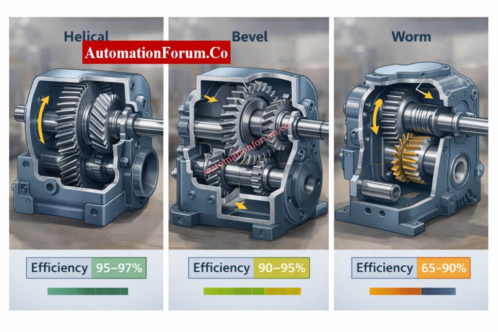
Gearboxes never transmit 100% of motor torque to the valve stem.
Typical efficiencies:
- Helical gearbox: 95-97%
- Bevel gearbox: 90-95%
- Worm gearbox: 65-90%
The calculator explicitly divides required torque by gearbox efficiency, ensuring that usable torque at the valve shaft is sufficient.
Ignoring efficiency can undersize actuators by 20-35%.
Select valves for harsh service: Control Valve Selection and Recommended Practices for Harsh Process Conditions
How the Valve Actuator Sizing Calculator Works
The calculator is built to replicate how experienced EPC engineers think, not just to perform arithmetic.
Review applicable valve standards: Codes and Standards for Control Valve Selection in Industrial Applications
Engineering Logic Used in the Calculator
- All torque components are summed before safety factor application
- Gearbox efficiency is applied as a loss, not a multiplier
- Actuator selection is based on continuous torque rating
- Gear ratios are selected from standard industry ratios
- The lowest ratio meeting torque requirements is selected
This avoids over-engineering while still ensuring reliability.
Practice control valve MCQs: Top 25 MCQs on Control Valve Types, Selection, and Applications for Project Engineers
Ball Valve Actuator Sizing Example – Step-by-Step Calculation
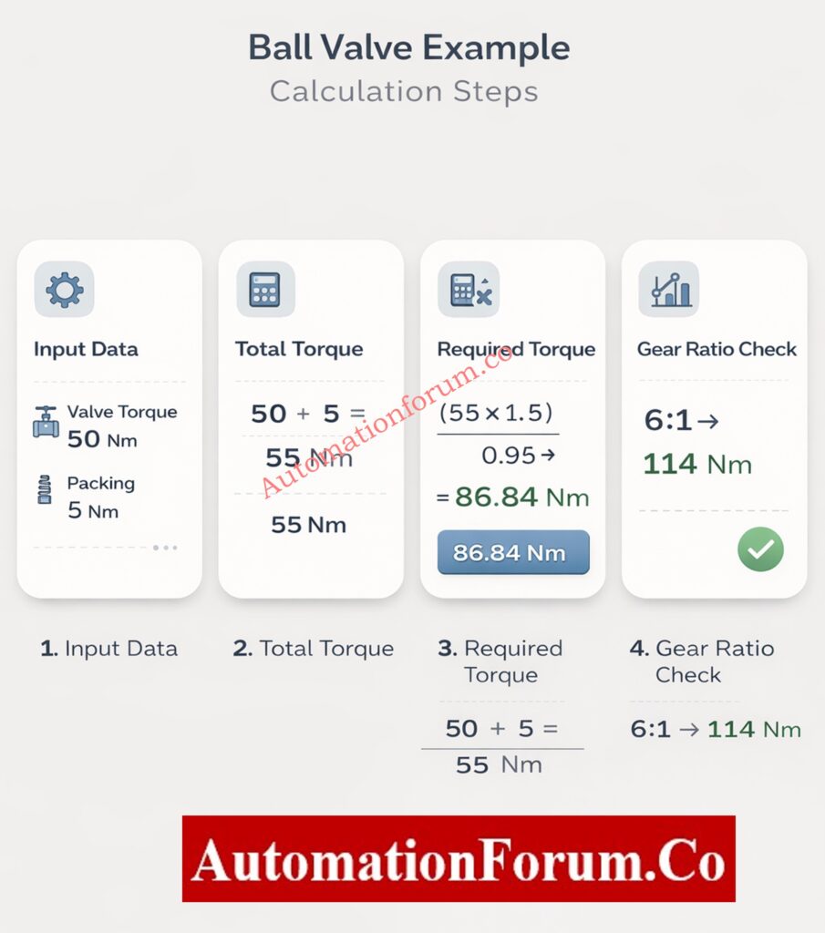
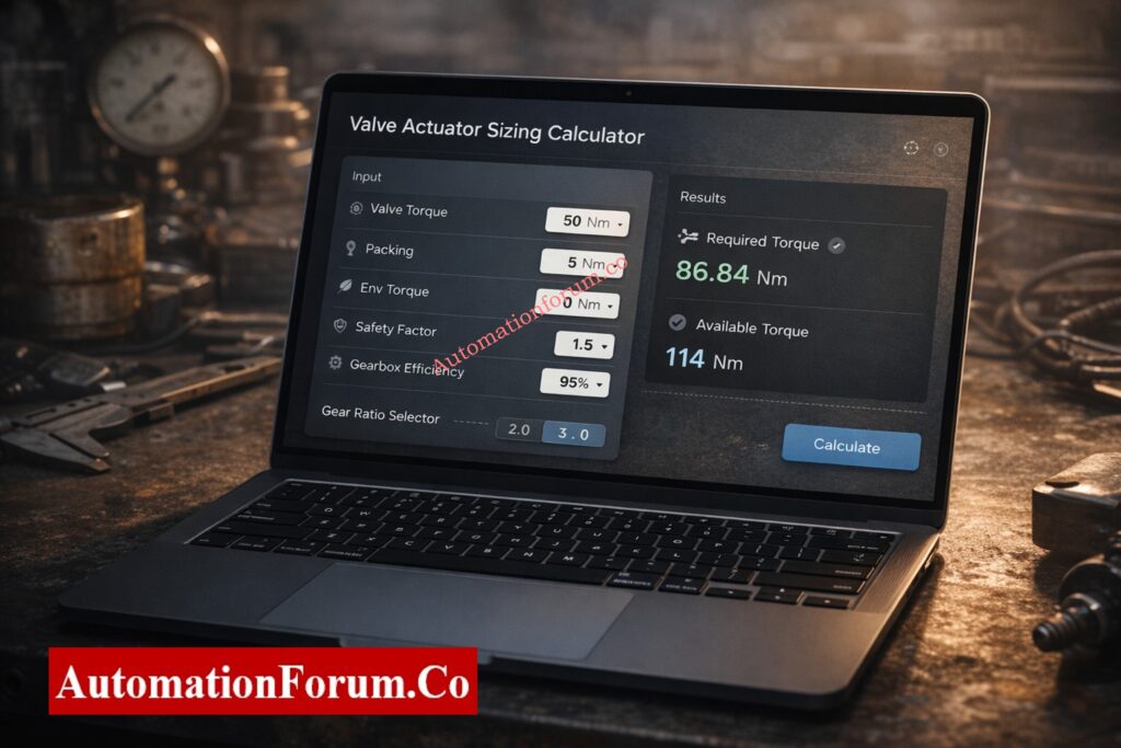
Input Data for Actuator Sizing
- Valve torque: 50 Nm
- Packing friction: 5 Nm
- Environmental torque: 0 Nm
- Safety factor: 1.5
- Gearbox efficiency: 95%
- Actuator continuous torque: 20 Nm
- Motor speed: 1500 RPM
Step 1: Total Torque Calculation
Total Torque = 50 + 5 + 0 = 55 Nm
Step 2: Required Torque Calculation
Required Torque = (55 × 1.5) ÷ 0.95 = 86.84 Nm
Step 3: Gear Ratio Evaluation
Available torque is checked against standard ratios:
- 4:1 → insufficient
- 6:1 → acceptable
Available Torque = 20 × 6 × 0.95 = 114 Nm
Refer the below link to understand valve flow characteristics importance in EPC Instrumentation and Control Engineering
Step 4: Final Actuator Selection Output
- Required torque: 86.84 Nm
- Available torque: 114 Nm
- Practical torque margin: ~27%
- Output speed: 250 RPM
This confirms a safe and efficient actuator selection.
Use valve sizing worksheet: Control Valve Sizing Calculation Worksheet for Critical and Sub-Critical Flow
Understanding Torque Margin in Valve Actuator Sizing
Torque margin is not about oversizing – it is about reliability over plant life.
Recommended margins:
- Control valves: ≥20%
- Shutdown valves: ≥30-40%
Higher margins are justified when:
- Valve is rarely operated
- Media causes fouling or deposits
- Valve is part of a safety instrumented function
Insufficient margin leads to:
- Actuator stalling
- Overheated motors
- Gear tooth failure
Learn importance of Cv: Why Measuring Control Valve Cv is Essential for Proper Valve Sizing ?
Gear Ratio Selection and Valve Stroke Time Considerations
Gear ratio affects both torque and speed.
Engineering trade-offs:
- Higher ratio → more torque, slower operation
- Lower ratio → faster operation, less torque
Always validate:
- Valve open/close time
- Process constraints
- Water hammer risk
The calculator outputs shaft RPM, which should be converted to stroke time during final verification.
Continuous Torque vs Peak Torque – Engineering Comparison
| Aspect | Continuous Torque | Peak Torque |
| Definition | Torque the actuator can deliver continuously without overheating or mechanical damage | Maximum short-duration torque available during start-up or stall conditions |
| Usage for sizing | Must be used for actuator sizing and selection | Must not be used for sizing |
| Duration | Sustained operation over the full duty cycle | Very short duration only |
| Thermal impact | Within motor and gearbox thermal limits | Causes rapid temperature rise if sustained |
| Effect of duty cycle | Fully accounted for in the rating | Usually not related to duty cycle |
| Ambient temperature | Rated for specified worst-case ambient temperature | Often quoted at ideal or short-term conditions |
| Reliability impact | Ensures long-term reliable operation | Leads to overheating and premature failure if misused |
| Typical EPC practice | Used for design, datasheets, procurement and verification | Used only for reference, never for final selection |
Solve actuator field problems: Common Challenges and Solutions for Industrial Control Valve Actuators
Typical EPC Applications of This Valve Actuator Sizing Methodology
This actuator sizing methodology can be applied across multiple phases of an EPC project and throughout the valve life cycle.
FEED and Detailed Engineering Phase
During front-end and detailed engineering, this approach helps establish realistic actuator torque requirements based on valve data, service conditions, and design margins. It supports early standardization and prevents late design changes during procurement.
Actuator Datasheet Preparation
You can immediately copy the calculated needed torque, safety factor, and gearbox ratio into actuator datasheets. This makes ensuring that vendor quotes are based on consistent and technically sound sizing standards.
Vendor Bid Evaluation and Technical Clarification
The size findings give you a straightforward way to compare vendor bids. You can objectively check actuator torque ratings, gearbox efficiency, and proposed gear ratios against the projected needs. This lowers the chance of making a wrong choice.
FAT and SAT Verification
You can use the size calculations to check the performance, torque capabilities, and stroke time of the actuator during factory and site acceptance testing. Any difference between what the design was meant to do and what it really does can be found early.
Brownfield Valve Automation Projects
This sizing method lets engineers look at existing valves again using current process conditions and choose the right actuators without having to rely on old or incomplete paperwork for refit or automation projects.
This structured approach helps maintain consistency between design calculations, procurement specifications, and commissioning performance, reducing operational risks and rework.
Compare linear and rotary: Difference between Linear and Rotary Actuator
Final Engineering Validation Checklist
Before approving the actuator selection, the following checks should be completed to avoid commissioning and long-term reliability issues.
Verification of Torque Components
Verify that valve operating torque, packing or friction torque, and environmental allowances are all included in the calculation. Using only the valve datasheet torque can result in undersized actuators.
Validation of Safety Factor Application
Confirm that the safety factor is applied to the total combined torque and not only to the valve torque. The chosen value should fit the valve’s job, like controlling service or shutting down in an emergency.
Confirmation of Gearbox Efficiency Inclusion
Make sure that the computation includes gearbox efficiency as a loss. To prevent underestimating actuator torque needs, lower efficiency, especially for worm gearboxes, must be taken into account.
Review of Torque Margin
Make sure that there is enough extra torque above what is needed. For control valves, a minimum of 20% is usually required, and for safety-critical valves, a higher percentage is usually advised.
Verification of Output Speed and Stroke Time
After choosing a gearbox, check the actuator output speed again to make sure that the times for opening and closing the valve match safety and process standards without generating shock or instability.
Understand actuator classifications: Classification of valve actuators – Electrical, Hydraulic and Pneumatic
Frequently Asked Questions on Valve Actuator Sizing
What is the formula for valve sizing?
The flow equation, which relates flow rate, pressure drop, fluid density, and valve coefficient (Cv or Kv), is often used to figure out the size of a valve. The basic equation is Q = Cv × √(ΔP / SG). The exact formula changes depending on whether the fluid is a gas, liquid, or steam.
Explore basic actuator types: Basic Types of Control Valve Actuators
How is PSV size calculated?
The size of a PSV is depending on its relieving capacity, set pressure, permitted overpressure, and the parameters of the fluid. To find the right orifice area, you use standard equations from API 520. The chosen PSV must be able to handle the desired flow without going above the maximum pressure limitations.
Improve process valve performance: Control Valve Sizing For The Process Performance
What is the actuator sizing program?
An actuator sizing program is a tool that helps you figure out how much torque or thrust an actuator needs. It takes into account the valve’s torque, friction, safety factor, and how well the gearbox works. The program tells you what size actuator and gear ratio you need.
Convert Cv to Cg: Cv to Cg for Gases Conversion Calculator: Control Valve Sizing
How do you select the right actuator?
To choose the proper actuator, you need to figure out how much torque or thrust is needed at the valve stem and compare it to the actuator’s continuous rated output. You also need to think about the type of valve, the circumstances of service, the duty cycle, and the speed requirements.
Download liquid sizing Excel: Control Valve Sizing Excel tool Without Iteration: Liquid Application
How to determine actuator size?
To find the size of an actuator, add up the valve torque, friction, and environmental allowances, and then add a safety factor. To figure out the minimal continuous actuator torque needed, we take into account the losses in gearbox efficiency.
What is a 3 point actuator?
A 3 point actuator is an electrically operated actuator that has three signals: open, close, and common. Instead of using an analog position signal, it adjusts the valve in small steps based on control inputs.
Refer the below link to Try PID tuning Simulation Tool for Engineers