
What is control valve sizing?
It is the process or the act of selecting an appropriate control valve for a particular application in the process industry.
The control valve sizing is an essential factor to be considered while selecting the right sized control valve for the required process to achieve the highest degree of process control for the liquid, gas, or multi-phase fluid.
How is the control valve sizing done?
The control valve size for the particular process should be selected in such a way that the control valve will operate between 60% and 80% of valve opening to achieve a maximum required flow rate, and not much less than 20% of valve opening at the minimum required flow rate.
The following are the three possibilities in the process of sizing and selection of control valves for a particular application.
1. The valve is correctly sized.
2. The valve is oversized.
3. The valve is undersized.
Correct Size Control Valve:
A correctly sized control valve called a right control valve that has the capacity to deliver the accurate fluid flow at minimum, normal and maximum valve openings.
This will help us to safeguard the optimal control of both comfort and the economy is concerned.
Oversized Control Valves (Large Cv):
An oversized control valve called large control has poor controllability. An oversized control valve implies that all normal operations will be confined to small openings of the valve with a great risk of variable sensitivity and the worst condition of any uneven movement of the valve leads to poor accuracy and unstable control.
The smallest change in valve stroke in an oversized control valve will result in higher flow rate variations.
As the valve gets opened or closed the large flow speeds and powerful turbulence are created between the valve plug and seat. This may gradually destroy the valve and will cause noise and may cause hunting in the valve system.
When a valve is operated below 10% of its Cv for an extended period of time, the valve seat and the closure member may get damaged.
Undersized Control Valves (Small Cv):
If the control valve is undersized it means the Cv of the valve is too small.
It is not possible to achieve the required flow rate even if the valve is fully opened.
If a higher pressure to the control valve is applied to force a higher flow rate across the undersized control valve, not only the pump energy will be excessive, and cavitation or flashing in the valve will occur.
What is the importance of the control valve sizing?
An undersized control valve doesn’t have the capacity to deliver the required flow rate of a fluid. And the oversized valve is very much sensitive to operating conditions
The following guidelines must be followed for accurate control valve sizing and selection.
- For a particular control loop if tuning parameters work only at either end of the control range, then the valve’s flow characteristic is considered wrong.
- An “equal percentage” control valve must be used when the differential pressure across the valve decreases as the flow rate increases.
- When the process gain decreases for an increase in flow rate an equal percentage valve can be used if not the linear control valve can be used.
- The proper-sized full ball valve, segment ball valve as well as high-performance butterfly valves are usually two sizes smaller than the line.
- The properly sized globe valves are usually one size smaller than the line.
The flow in the valve is regulated by varying its resistance as the valve is stroked, i.e. its effective cross-sectional area is changed.
As the fluid passes from the pipe into the valve the fluid velocity increases due to the reduced diameter of the valve orifice and enables mass flow through the valve.
The energy required to raise the velocity comes at the expense of the pressure, in the smallest cross-sectional area of the valve, the fluid pressure and velocity are inversely proportional.
The vena contract is a point where the fluid pressure is at its minimum. The valve is simplified to an orifice to display the general behavior of the fluid flow through the control valve.
Control valve sizing equations:
To select the appropriate size of the control valve for a particular application the flow coefficient is an important factor to be considered.
The flow coefficient is also known as a capacity parameter.
A. For liquids:
The flow rate of incompressible fluids like water and oil depends on the difference between inlet and outlet pressure.
For the system having higher or lower pressure, the flow rate is constant. The valve size required for liquids like water and oil can be calculated using the below equation

Where,
Cv = flow coefficient of the valve.
Q = Fluid flow rate,
S = Specific gravity of liquid.
?P = differential pressure.
The specific gravity of water below 200°F is 1.0 to calculate the valve size for the fluids with viscosity correction factor K

Where K is the viscosity correction factor
B. Estimating diameter of pipe:
Estimating pipe diameter is another important factor to be considered in sizing and specifications.

Where:
d = diameter of the pipe in feet.
Q max = maximum flow through the valve.
V = velocity of fluid flowing through the valve
C. For Air and Gas:
The flow rate calculation for compressible fluids like natural gas, propane, and the air is slightly complex because density changes with a change in pressure. The following are two conditions that must be considered are
- Low-pressure drop flow
- High-pressure drop flow.
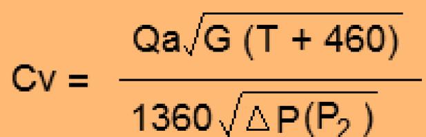
To calculate the valve coefficient for outlet pressure (P2) is greater than one-half of inlet pressure (P1) the following equation can be used.
To calculate the valve coefficient for outlet pressure (P2) is less than one-half of inlet pressure (P1) the following equation can be used.

Where,
Cv = Valve flow coefficient, US GPM with P = 1 psi
Qa = Air or gas flow, in SCFH at 14.7 psig and 60F i
T = Air/Gas temperature flowing through the valve
?P = pressure difference
P1 and P2 = Inlet and Outlet pressure at maximum flow
The relationship between the inlet and outlet pressure in the case of gaseous is important in determining which equation to use for gaseous flow.
When the pressure drop is critical the gas will behave differently and therefore it is necessary to use the correct equation depending on the extent of the pressure drop.
Once the desired value of Cv is calculated, The valve selected must have a greater or equal valve coefficient than the computed value.
D. For saturated or superheated steam:
When outlet pressure P2 is greater than ½ of inlet pressure P1 then

When outlet pressure P2 is lesser than ½ of inlet pressure P1 then

Where,
Cv is valve flow coefficient
W = Steam flow in pounds per hour.
K = 1 + (0.0007 x F) for superheated steam
?P = Pressure drop in psi
P1 and P2 = Inlet pressure and outlet pressure at maximum flow
Some useful Questions:
What is a critical pressure drop?
When the outlet pressure is less than ½ of the inlet pressure it is known as a critical pressure drop.
What is the control valve flow coefficient?
The flow coefficient is defined as the number of gallons per minute.
What is the critical temperature?
The critical temperature is the temperature at which a gas cannot be converted into a liquid by pressure.
What is cavitation?
Cavitation is a condition where vapor bubbles arise if the internal pressure of the liquid falls below vapor pressure when the liquid is passed through the control valve.
The cavitation occurs only with liquid but not in gasses.
This vapor pressure recovers so the bubbles collapse, and Cavitation takes place. Cavitation in the valve will sound like stones passing through the valve.
What is Flashing?
Flashing is a condition that occurs with the liquid flow where the pressure of the liquid falls below the vapor pressure and remains below it.
Flashing causes severe damage inside a valve due to erosion caused by the impact of liquid droplets traveling at high speeds.
What is the difference between solid, liquid, vapor, and gas?
The fluids can exist in different states or phases like solid, liquid, vapor, and gasses. The state or phase depends on the current temperature and pressure.
Let us consider H20 as an example
H2O can exist as a
- Ice in the solid phase,
- Water in the liquid phase,
- Saturated steam in the vapor phase.
- Superheated steam in the gas phase
What is the specific gravity of fluid?
Specific gravity is defined as the relative weight of the fluid compared to an equal volume of water.
What are compressible fluid and incompressible fluid?
- Compressible fluids: there are fluids in which the density varies from one point to another point.
- Incompressible fluids: there are fluids in which the density does not vary. It means the density remains constant.