The Control Valve Sizing Calculation Worksheet serves engineering and professional users who perform control valve sizing tasks for liquid systems. The worksheet serves to determine the correct valve dimensions while optimizing performance and flow control effectiveness in critical and sub-critical situations. The tool delivers structured valve selection methodology that helps engineers prevent inadequate valve choices which adversely affect process efficiency and costs.
Key Features of Control Valve Sizing Calculation Worksheet
Project Details Section
Includes fields for recording essential project-specific information such as:
- Date of calculation
- Prepared by, Checked by, and Approved by
- Project Name, Client Name, and Location
- Subject of the calculation
- Additional remarks or notes for reference
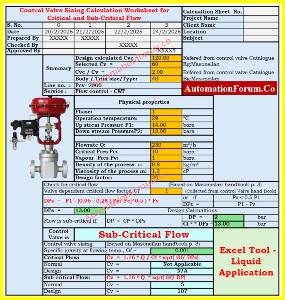
Calculation Summary
Displays crucial calculation results, including:
- Design Calculated Cv (Cvc): The required valve flow coefficient based on process parameters.
- Selected Cv: The Selected Cv represents the actual Cv value which manufacturers offer among their available options.
- Cvc / Cv Ratio: Cvc dividing Cv value serves to check the appropriate selection of valves and validate their operational capacity range.
- Body and Trim Size/Type:Users need details on physical and mechanical valve characteristics which confirm process suitability through Body and Trim Size/Type information.
- Pressure Drop Considerations: The assessment determines if the valve pressure drop stays within appropriate ranges to stop cavitation and flashing occurrences.
Must Read: Control Valve Flow Coefficient (Cv) in Industrial Applications
Technical Considerations
The worksheet includes evaluation of critical factors:
- The worksheet considers three flow rate levels which include minimum and normal along with maximum settings.
- Inlet and outlet pressures
- The worksheet analyzes liquid characteristics regarding both fluid density and viscous properties.
- The worksheet addresses three vital factors about valves: types of valve and selected trim options and built-in characteristics.
- Determination of flow regime: sub-critical or critical flow conditions
- The assessment includes detecting signs of cavitation and flashing since these problems reduce both valve performance and service life.
Refer: Control Valve Cv Calculation Excel Tool for Liquid, Gas, and Steam Services
Reference to Control Valve Catalogues
The worksheet refers to well-known control valve manufacturers such as:
- Masoneilan
- Fisher
- Samson
- Other industry-standard brands
- The chosen valve needs to fulfill the requirements supported by industry standards and performance benchmarks and engineering best practices.
- The chosen control valve comes from Masoneilan but additional verification of the selection process is essential because the calculations are not complete.
Useful Resource: Cv to Cg for Gases Conversion Calculator: Control Valve Sizing
Download: Control Valve Sizing Calculation Worksheet (Excel Tool)
The Excel-based tool functions as an essential professional tool which helps experts achieve optimal flow control while selecting valves to guarantee safety along with cost-effectiveness and operational excellence. The worksheet enables engineers to make decisions supported by exact calculations and established industry standards for decision making.
Refer the below link to Download the Control Valve Sizing Calculation Worksheet
Applications of Control Valve Sizing Calculation Worksheet
This tool is particularly useful for:
- Process engineers designing control systems for fluid applications.
- Mechanical engineers selecting valves for pipelines and industrial processes.
- Instrumentation engineers ensuring accurate control over fluid regulation.
- Professionals in the oil & gas, chemical, pharmaceutical, power generation, and water treatment industries where precise control of fluid flow is critical.
- Engineers involved in plant commissioning and troubleshooting valve performance issues.
Why It Matters: Why Measuring Control Valve Cv is Essential for Proper Valve Sizing ?
Benefits of the Worksheet
- The worksheet helps select valves correctly which results in reduced operational inefficiencies and unnecessary costs.
- The worksheet saves time through its structured automatic valve sizing method which eliminates human mistakes.
- The worksheet improves control system reliability through automatic suggestions of proper valve setups which rely upon calculated parameters.
- The worksheet helps users detect cavitation and flashing and choked flow occurrences to achieve longer service life for valves along with their connected equipment.
- The proper control valve functioning in all process environments improves safety through reduced risks of overpressure and flow instability.
- Choosing control valves according to industry standards and regulatory guidelines becomes achievable through best practices that adoption facilitates compliance.
- Complete dataset entry becomes mandatory to prevent errors and achieve proper valve sizing since all essential information remains available for precise calculations.
Excel-based tools function as crucial professional tools for flow control due to their ability to enhance valve selection performance as well as safety and cost efficiency. Using this worksheet provides engineers access to accurate calculations and established industry methodologies to support their decision-making process.
Essential Guide: Relationship Between Cv and Kv in Control Valves
FAQ on Control Valves CV and Flow Characteristics
What is the difference between rated Cv and calculated Cv?
When fully open the valve shows its maximum flow capability through the flow coefficient known as Rated Cv. The value of Calculated Cv derives from particular operational parameters that combine inlet pressure (P1) with outlet pressure (P2) along with flow rate and specific gravity of process fluids. Using calculated Cv enables users to choose correct valves that will operate under both the application’s least and greatest flow requirements.
How is control valve sizing determined?
The proper way to size control valves involves maintaining their operation between 20% and 80% open during maximum flow conditions. Keeping a minimum opening of 20% ensures protection across the operational range since it creates a safety buffer at the lowest flow requirement. The desired flow stability and valve operational efficiency result from this design approach.
How is the valve Cv calculated for liquid flow?
The volume flow rate of liquids can be determined through the multiplication of flow area with fluid velocity. A valve’s flow capability at 60°F expressed through Cv indicates the volume measure of water which flows through the valve within one minute at a 1 psi pressure difference. The standardized measurement enables simple capacity evaluation between valves.
What is the difference between critical and subcritical flow?
A flow classification depends on the value of the Froude number (Fr)::
- Critical Flow: Flow becomes critical when fluids attain wave propagation speed matching their movement speed which gives a Froude number equal to 1.0.
- Subcritical Flow: A flow is classified as Subcritical when its Froude number becomes smaller than 1.0 leading to slower movement rates and greater depth levels..
- Supercritical Flow: Supercritical flow exists when the value of the Froude number exceeds 1.0 resulting in fast-moving fluid with shallow depths.
What is critical flow in a control valve?
A restriction such as a valve produces critical flow when gas moves at sonic speed (Mach 1). Gas flow control system design heavily depends on this condition because it sets the upper limit on the system’s flow rate.
What is an example of subcritical flow?
A subcritical flow state exists when a river descends gently while maintaining a wide smooth bed which allows water to move at slow velocities keeping the water surface flat. The flow state of subcritical occurs when both velocity remains low alongside deep flow conditions.