- Step-by-Step Procedure interpreting hookup drawing
- Step 1: Title Block and General Information
- Step 2: Referring the Notes Section
- Step 3: Identify Process Flow Direction
- Step 4: Main Components and Symbols
- Step 5: Referring the Component List / Bill of Materials (BOM)
- Step 6: Connection Details
- Step 7: Scope of Work
- Step 8: Dimensional Requirements
- Step 9: Installation Specifications
- Step 10: Component Details
- Detailed Analysis of the Sample Drawing
- Additional Suggestions for Reading Hook-up Drawing
Reading and interpreting control valve hookup drawings is an essential skill for instrumentation installation engineers and technicians. These drawings provide detailed instructions on how to install and configure control valves within a system, ensuring proper operation and integration.
Here’s a guide on how to read a control valve hookup drawing, followed by a detailed explanation of the provided example drawing:
Step-by-Step Procedure interpreting hookup drawing
Step 1: Title Block and General Information
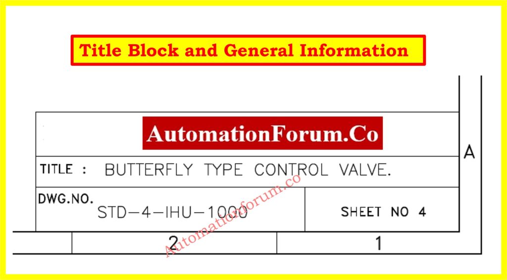
Title:
- Located at the bottom right and indicates the type of control valve, e.g., “Butterfly Type Control Valve”.
- Helps in quickly identifying the drawing’s purpose.
Drawing Number:
- Found within the title block and crucial for reference and document control, e.g., “DWG.NO. STD-4-IHU-1000”.
- Uniquely identifies the drawing within a set of documents.
Revision and Sheet Number:
- Also located in the title block.
- Revision Number indicates the version of the drawing (e.g., Rev 1, Rev 2).
- Sheet Number identifies the drawing’s place within a set (e.g., “Sheet 4 of 4”).
Company Information:
- Included in the title block. Indicates the organization responsible for the drawing, Useful for accountability and contact information.
Step 2: Referring the Notes Section
Read the notes carefully; they provide specific instructions and important details about the installation.
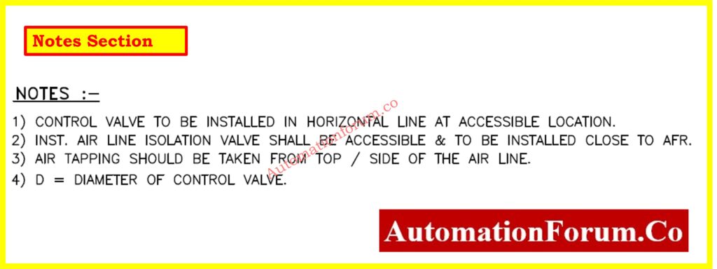
- Example: Note 1 specifies that the control valve should be installed horizontally and in an accessible location.
- Example: Note 2 states that the instrument air line isolation valve should be accessible and installed close to the AFR (Air Filter Regulator).
- Example: Note 3 instructs that air tapping should be taken from the top or side of the air line.
- Example: Note 4 defines D as the diameter of the control valve.
Click here to more about Instrument Location Layout
Step 3: Identify Process Flow Direction
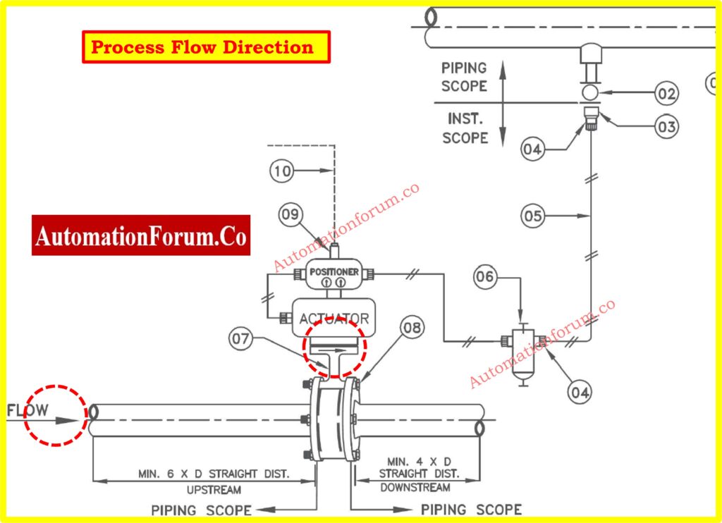
- Look for an arrow on the drawing, which indicates the direction of the process flow.
- The arrow shows how the medium (e.g., gas, liquid) moves through the system.
- Use the flow direction to correctly orient the valve and associated components.
- For example ensure that the control valve is installed so that the flow matches the direction indicated by the arrow.
- Identify the upstream and downstream sides of the valve, often specified by minimum straight pipe lengths (e.g., 6D upstream, 4D downstream).
- Proper orientation prevents installation errors that could lead to operational issues or system failures.
Step 4: Main Components and Symbols
- Carefully examine the drawing to locate and identify various symbols representing different components.
- Refer to the diagram legend or within the drawing itself to understand what each symbol represents.
- Valve is Indicated by specific valve symbols, like a butterfly valve.
- Actuator is Shown as devices that control the valves(top of butterfly valve).
- Tubing represented by lines connecting various components.
- Fittings Symbols showing connectors between pipes and tubes.
- Check Connections to ensure you understand how each component is interconnected based on the symbols.
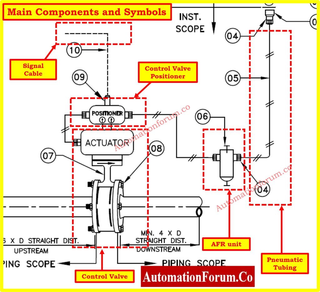
- Signal Cables are Often indicated by dashed lines, showing the connection between the control system and actuators.
Step 5: Referring the Component List / Bill of Materials (BOM)
- BOM Typically found at the bottom or side of the drawing, the BOM provides a detailed list of all components required.
- Columns of the BOM usually includes columns for item number (SR. NO), description, size, quantity, and notes.
- Check the material specifications to ensure compatibility with the process conditions (e.g., stainless steel, brass).
- Always cross-reference the BOM with the main drawing to confirm the placement and connection of each component.
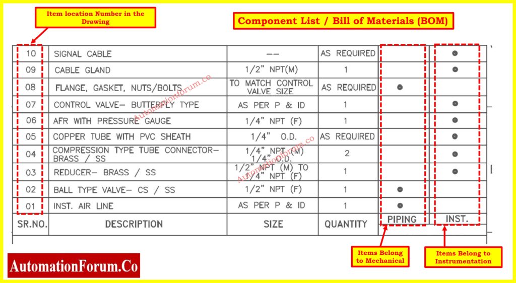
Refer to the BOM for a detailed list of components, their sizes, quantities, and material specifications.
For Example SR. NO 07: “Control Valve – Butterfly Type, As per P & ID, Quantity: 1”.
- Description Indicates the type of control valve.
- Size are Specified according to the process and instrumentation diagram (P&ID).
- Quantity Specifies that one unit of this control valve is required.
Click here to know more about Instrument Bill of Material
Step 6: Connection Details
- Examine the lines in the drawing to understand how each component is connected.
- Solid Lines are typically represent piping or tubing that physically connects components.
- Dashed Lines are often indicate signal or electrical connections.
- Use the symbols identified in Step 4 to follow the connections.
- Ensure each symbol corresponds to the correct component in the BOM.
- For example Signal Cable (SR. NO 10) Connects to the actuator, indicating control signals from the control system to the actuator.
- Ensure the cable gland (SR. NO 09) is used for secure connection of the signal cable.
- Mechanical Connections are Indicated by direct lines connecting components like valves and actuators.
- Instrumentation Connections are Shown by dashed or dotted lines representing signal or pneumatic lines.
- Ensure all connections align with the process flow direction identified in Step 3.
- Verify that Upstream and Downstream components are correctly positioned relative to each other to maintain proper flow.
Step 7: Scope of Work
- The drawing is divided into sections like “Piping Scope” and “Instrument Scope”, indicating the boundaries of work for different teams.
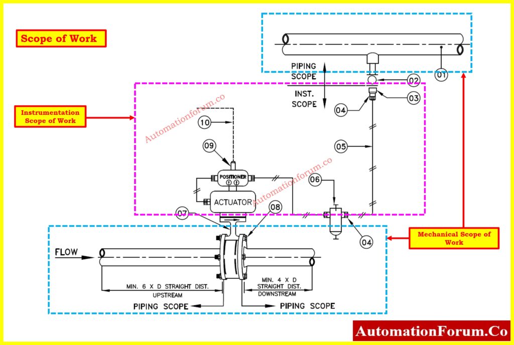
- For Example the piping scope includes the installation of the control valve and associated piping, while the instrument scope covers signal cables and instrumentation.
Step 8: Dimensional Requirements
- Pay attention to dimensional notes, such as the required straight pipe lengths upstream and downstream of the valve (6D and 4D respectively).
Step 9: Installation Specifications
- Review specific installation instructions, such as the positioning of air line tapping (Note 3: from the top or side of the air line).
Step 10: Component Details
- Refer to the callouts on the drawing that provide more information about each component.
- For example the air filter regulator (AFR) with a pressure gauge is indicated with a specific callout showing its connection details.
Click here to more about Instrument Hook-up Diagrams
Detailed Analysis of the Sample Drawing
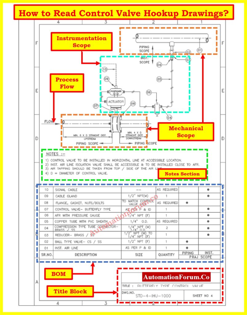
Title Block
- Company: xxxxxxxxxxxxxxxx
- Title: Butterfly Type Control Valve.
- Drawing Number: STD-4-IHU-1000.
- Sheet Number: 4.
Drawing Area – Piping Scope(Mechanical)
Flow Direction:
- An arrow indicates that the flow is from left to right across the control valve.
Upstream and Downstream Distances:
- Minimum 6D straight distance upstream of the control valve.
- Minimum 4D straight distance downstream of the control valve.
- D represents the diameter of the control valve, ensuring sufficient straight piping for accurate flow measurement and control.
Main Components:
- Control Valve (07) is butterfly type valve and Installed horizontally for accessibility and ease of maintenance also Includes an actuator (08) mounted on the valve for operation.
- Actuator (08) Controls the valve by pneumatic electrical signals
- Air Line is Connected to the actuator for control, ensuring proper operation of the control valve.
Click here to know more about Instrument Air Header Schedule
Drawing Area – Instrumentation Scope
Instrument Air Line (01):
- Supplies air to the control valve, essential for pneumatic actuators.
Ball Type Valve (02):
- ½” NPT(F) connection, used for isolating the air line.
- Material: CS (Carbon Steel) or SS (Stainless Steel).
Reducer (03):
- Converts from ½” NPT(M) to ¼” NPT(F).
- Material: Brass or Stainless Steel, providing a connection between different pipe sizes.
Compression Type Tube Connector (04):
- Connects the tubing to the air line or AFR.
- Sizes: ¼” NPT(M), ¼” O.D. (Outer Diameter).
- Material: Brass or Stainless Steel.
Copper Tube with PVC Sheath (05):
- Size: ¼” O.D.
- Connects the air line to the AFR, protecting the tubing with PVC sheath.
AFR with Pressure Gauge (06):
- Size: ¼” NPT(F).
- Regulates the air pressure supplied to the actuator, ensuring proper operation.
Signal Cable (10):
- Connects the control valve to the control system, enabling monitoring and control signals.
Notes Section
- Control valve must be installed horizontally for accessibility.
- Ensures easy maintenance and operation.
- Air line isolation valve should be accessible and installed close to the AFR (Air Filter Regulator).
- Facilitates easy operation and maintenance.
- Should be taken from the top or side of the air line.
- Ensures accurate pressure measurement and avoids moisture accumulation.
- D represents the diameter of the control valve.
- All measurements and installation distances are based on this diameter.
Bill of Materials (BOM) with Location Number
The BOM provides a detailed list of all components required for the installation, ensuring nothing is overlooked:
Instrument Air Line:
- As per P&ID (Piping and Instrumentation Diagram).
- Ensures correct specification and routing.
Ball Type Valve (02):
- ½” NPT(F), CS or SS.
- Used for isolating the instrument air line.
Reducer (03):
- Brass or SS, ½” NPT(M) to ¼” NPT(F).
- Adapts different pipe sizes.
Compression Type Tube Connector (04):
- ¼” NPT(M), ¼” O.D., Brass or SS.
- Connects the tubing securely.
Copper Tube with PVC Sheath (05):
- ¼” O.D.
- Ensures durability and protection.
AFR with Pressure Gauge (06):
- ¼” NPT(F).
- Regulates and monitors air pressure.
Control Valve (07):
- Butterfly type, as per P&ID.
- Main component controlling flow.
Flange, Gasket, Nuts/Bolts (08):
- Matches control valve size.
- Ensures proper sealing and connection.
Cable Gland (09):
- ½” NPT(M) size
- Secures signal cable entry.
Signal Cable (10):
- As required and Connects the control valve to the control system.
Understanding the Flow and Connections
- Instrument Air Line (01) supplies air to the system.
- Ball Type Valve (02) isolates the air line for maintenance or emergencies.
- Reducer (03) adjusts the line size from ½” NPT(M) to ¼” NPT(F).
- Compression Type Tube Connector (04) connects the reduced line to the tubing.
- Copper Tube (05) connects to the AFR (Air Filter Regulator).
- AFR with Pressure Gauge (06) regulates the air pressure supplied to the actuator.
- Actuator (08) receives controlled air from the AFR to operate the Butterfly Type Control Valve (07).
- Signal Cable (10) transmits control signals between the actuator and the control system.
Additional Suggestions for Reading Hook-up Drawing
Consulting With P&ID:
- The Process and Instrumentation Diagram (P&ID) provides a more comprehensive overview of the process flow and instrumentation setup.
- Includes all control loops, process equipment, piping, instrumentation details, and how they are interconnected.
- Use the P&ID to verify the correct placement and connection of components shown in the hookup drawing.
- If a discrepancy is found between the hookup drawing and P&ID, the Piping & Instrumentation Diagram (P&ID) should be referred to for the correct information.
Click here to know more about Piping & Instrumentation Diagram (P&ID)
Standards and Codes:
- Ensure all installations adhere to industry standards and regulatory codes, such as ASME, ANSI, IEC, or local regulations.
- Standards and codes are designed to ensure safety, reliability, and quality of the installation.
- Regularly check that all materials, components, and procedures conform to the relevant standards.
- The use of appropriate materials for flanges and fittings as specified by ASME standards to handle the process conditions.
Cross-Referencing other Documents:
- Cross-reference the hookup drawing with other related documents, such as specification sheets, equipment datasheets, and installation manuals.
- Ensure consistency and completeness across all project documentation to avoid errors and omissions.
- Cross-referencing helps in gaining a comprehensive understanding of the system, ensuring all components are correctly integrated.
- Checking the equipment datasheet to confirm the specifications of the control valve match what is indicated in the BOM and the P&ID.
Click here to Know more about different Types of Engineering Drawings and Documents used in Instrumentation


