- What is Voltage Drop in PLC Wiring?
- Why is Voltage Drop Calculation Crucial for PLC Systems?
- Voltage Drop Formula for PLC wiring
- Step-by-Step Guide to Calculating Voltage Drop in PLC wiring
- Example Calculation for PLC wring Voltage Drop
- Acceptable Voltage Drop Limits in PLC Systems
- How to Reduce Voltage Drop in PLC Systems
- Top Tools and Software for Voltage Drop Calculation
- PLC Wiring Voltage Drop Calculation – FAQ
- How do you calculate voltage drop in PLC wiring?
- What is the acceptable voltage drop in PLC wiring?
- What are the IEC standards for voltage drop in PLC wiring?
- What is considered a normal voltage drop in PLC circuits?
- What is the voltage drop per 100 feet in PLC wiring?
- What is the maximum voltage drop for a 230V PLC circuit?
- How can voltage drop be minimized in PLC wiring?
The performance and reliability of automation systems depend heavily on proper management of voltage drop within PLC wiring infrastructure. The guide provides a detailed explanation of voltage drop calculations while also exploring its impact and solution methods to support smooth PLC system execution.
What is Voltage Drop in PLC Wiring?
PLC wiring experiences voltage drop which creates essential considerations for system functionality.
The transmission of electrical current through wires causes voltage to decrease which results in voltage drop. Voltage drop occurs because wire materials naturally create resistance during electrical transmission. The application of high voltage drop causes multiple issues within PLC (Programmable Logic Controller) systems and produces the following results:
- Voltage drops in PLC systems and devices create operational failures.
- Inconsistent performance of sensors and actuators.
- Increased risk of system downtime and equipment damage.
Effective voltage drop management remains crucial to protect the performance quality as well as the reliability of your automation systems.
Why is Voltage Drop Calculation Crucial for PLC Systems?
The calculation of Voltage Drop remains vital for PLC System implementation because of multiple essential reasons.
- PLCs with their connected devices require a constant stable voltage for normal operation. High voltage drops will disrupt the normal operation of devices up to the point of complete failure.
- The process of identifying and fixing voltage drop issues helps prevent equipment outages while simultaneously decreasing operational downtimes.
- Electrical design standards require that voltage drops remain below 5% of the primary supply voltage. Adhering to these established standards helps maintain both safety measures and system reliability.
Voltage Drop Formula for PLC wiring
The voltage drop (Vdrop) in PLC wiring can be calculated using the following formula:

Where:
- I = Current (in Amperes, A)
- R = Resistance of the wire (in Ohms, ?)
For longer wires, the resistance depends on the wire’s length, cross-sectional area, and material. The formula for resistance is:

Where:
- L = Length of the wire (in meters, one-way distance)
- ? = Resistivity of the wire material (e.g., copper = 1.68×10?8??/m)
- A = Cross-sectional area of the wire (in square meters, m2)
Combining these, the voltage drop formula becomes:

Click here for How to solve the voltage drop problems over the long-distance cable?
Step-by-Step Guide to Calculating Voltage Drop in PLC wiring
- Determine the Current (I):The first step requires you to identify the current rating (I) which either belongs to your PLC device or to the equipment it controls. The device specifications provide this information to the user.
- Measure the Wire Length (L): You must measure the entire one-way distance that exists between the power source and the PLC unit. Include the complete length of the wire during measurement.
- Select the Wire Material and Size:The selection of wire material and size requires knowledge about wire resistivity (?) and wire gauge (AWG or mm²) to calculate cross-sectional area (A).
- Calculate the Voltage Drop:Use the determined values to calculate the voltage drop using the formula.
Example Calculation for PLC wring Voltage Drop
Let’s consider a practical example to illustrate the calculation:
- Current (I): 5 A
- Wire Length (L): 50 meters (one-way)
- Wire Material: Copper (?=1.68×10?8???m)
- Wire Size: 2.5 mm² (A=2.5×10?6?m2)
First, calculate the resistance (R):

Next, calculate the voltage drop (Vdrop):

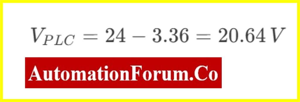
If the supply voltage is 24 V, the voltage at the PLC will be:
Refer the below link for How to do the voltage drop calculation of instrument cable?
Acceptable Voltage Drop Limits in PLC Systems
The proper functionality of Programmable Logic Controller (PLC) systems depends highly on having stable voltage supplies. A substantial voltage drop can create system failures as well as cause sensor reading inconsistencies while generating electrical system malfunctions. The voltage drop in a power system should remain within 5% of the total supply voltage.
Common Voltage Drop Limits
- 24V System ? Maximum allowable drop: 1.2V (5% of 24V)
- 120V System ? Maximum allowable drop: 6V (5% of 120V)
When voltage drop reaches beyond acceptable levels it is necessary to perform corrective actions to maintain proper power delivery.
How to Reduce Voltage Drop in PLC Systems
All voltage drop calculations depend on three major elements which include wire resistance together with wire length combined with current draw. The following methods prove effective in reducing voltage drop disturbances:
1. Use a Larger Wire Size
- The resistance of a wire is inversely proportional to its cross-sectional area. Increasing the gauge size (reducing wire resistance) decreases the voltage drop.
- Example: Switching from AWG 18 to AWG 14 can significantly reduce resistance and improve voltage stability.
2. Reduce Wire Length
- Voltage drop is directly proportional to wire length. The longer the wire, the greater the resistance and, consequently, the voltage drop.
- To minimize this effect:
- Place the PLC closer to the power source.
- Route cables efficiently to avoid unnecessary length.
3. Increase Supply Voltage
- A 48V power supply should replace the existing 24V system enabling subsequent voltage reduction near the PLC. A higher supply voltage allows for reduced current flow while maintaining power levels leading to decreased voltage loss through the cable
Additional Considerations
- Proper connectors and terminals must be used because corrosion and loose connection points elevate resistance levels and decrease voltage.
- Large loads connected to the same power circuit cause significant voltage reduction in the system. Install separate power lines whenever needed.
- The use of a Voltage Drop Calculator helps users predict voltage drop based on wire size and length and load characteristics.
Click here for Instrumentation Cable and Wiring Inspection Procedure: Essential checklist for Project Engineers
Top Tools and Software for Voltage Drop Calculation
Online Voltage Drop Calculators
The tools provide instant and straightforward functionality by demanding inputs for wire size with material type along with length and current measurement and input voltage.
Omni Calculator (Voltage Drop Calculator)
- A user-friendly online program provides immediate voltage drop calculations to its users.
- The platform supports measurements of various wire gauge types as well as different material choices of aluminum or copper and enables users to process single-phase or three-phase electrical circuits.
- The utility serves as an appropriate tool for conducting simple computations during PLC power circuit design.
Website Link: Omni Voltage Drop Calculator
Southwire Voltage Drop Calculator
- A reliable tool for accurate voltage drop calculations.
- Users can choose from a list that contains wire gauge information together with length details and material specifications as well as voltage parameters and current measurements.
- The system presents recommendations about resolving voltage drop issues that exceed safe limits.
Website link: Southwire Voltage Drop Calculator
PLC Wiring and Electrical Design Software
- For more advanced electrical design, dedicated software can automate calculations and optimize wiring layouts.
- Advanced software like EPLAN and AutoCAD Electrical can automate voltage drop calculations and optimize wiring designs.
- EPLAN Electric P8 suitable for Industrial automation projects and complex PLC system designs.
- AutoCAD Electrical suitable for Large-scale electrical system design with PLC integration.
You must read to know about Various types of Wirings in PLC & DCS Systems
PLC Wiring Voltage Drop Calculation – FAQ
How do you calculate voltage drop in PLC wiring?
Voltage drop in PLC wiring can be determined through the product of distance in feet (one-way) and current (amps) divided by phase conductors. Calculate the permissible voltage drop value then divide it by 1,000,000 after multiplication with the results from the first step.
What is the acceptable voltage drop in PLC wiring?
A proper operating PLC requires both control and power wiring voltage drops to remain below 5%. The design protects signal transmission reliability while preventing any problems caused by voltage issues.
What are the IEC standards for voltage drop in PLC wiring?
The maximum allowable voltage drop specified by IEC and IET standards amounts to 3% for lighting loads alongside 5% for inductive loads to ensure operational reliability in automation systems. The IEEE offers a more reactive guideline of accepting maximum voltage drop at 2.5%.
What is considered a normal voltage drop in PLC circuits?
The NEC (National Electrical Code) permits a voltage drop of up to 5% at the farthest connected device in a PLC system. For a 120V, 15A circuit, this corresponds to a maximum drop of 6V under full load conditions.
What is the voltage drop per 100 feet in PLC wiring?
A typical voltage drop exists at 0.75V across every 100 feet of wire but wiring gauge together with load and resistance determine the actual values. When voltage drop stays within limits PLC signal transmission remains accurate.
What is the maximum voltage drop for a 230V PLC circuit?
The IEC guidelines state that 6.9V is the maximum allowed voltage drop for 230V single-phase PLC circuits when controlling lights while the permitted drop for other loads reaches 11.5V.
How can voltage drop be minimized in PLC wiring?
A reduction of voltage drop in PLC control and power circuits can happen through these methods:
- A higher wire gauge selection reduces circuit resistance.
- Shorten cable runs wherever possible
- Voltages should be regulated through devices to maintain steady operation.
- The terminal connections need optimization together with a reduction in the number of splices.
- Power factors need correction through implemented techniques to achieve operational efficiency.
- System maintenance performed often leads to minimum voltage drops while helping defend PLC systems from unexpected failures.