- What Is Impulse Line Inspection and Why It Is Critical for DP Transmitters
- Scope of Impulse Line Inspection in Process Industries
- Safety Requirements Before Performing Impulse Line Inspection
- Tools Required for Effective Impulse Line Inspection
- Step by Step Impulse Line Inspection Procedure for DP Transmitters
- Real Field Case Study: Sluggish DP Transmitter Caused by Condensate
- Acceptance Criteria for a Healthy Impulse Line System
- Completion and Handover
- Impulse Line Inspection Checklist for Routine Rounds
- How Regular Impulse Line Inspection Prevents False DP Readings
What Is Impulse Line Inspection and Why It Is Critical for DP Transmitters
This procedure defines a detailed step by step method for routine running inspection of impulse lines and process connections associated with differential pressure pressure and flow transmitters. The objective is to ensure accurate measurement fast dynamic response and reliable control performance by preventing false readings caused by blocked impulse lines condensate accumulation trapped air leakage vibration improper routing and incorrect valve positioning. This procedure is intended for use by instrumentation technicians maintenance engineers and supervisors during normal plant operation.
Impulse Line Problems & Solutions: What are Impulse lines? – Impulse line problems and solutions
Scope of Impulse Line Inspection in Process Industries
This procedure applies to all impulse lines connected to differential pressure pressure and flow transmitters installed in gas liquid steam and multiphase services. The procedure is applicable during routine rounds normal operation and condition based maintenance activities. It does not replace shutdown maintenance or major modification procedures.
Instrument Tubing Pressure & Leak Test Method: Method Statement for Pressure Test and leak Test for Instrument Tubing and Impulse line
Safety Requirements Before Performing Impulse Line Inspection
- Impulse lines shall always be treated as pressurized and potentially hazardous.
- Personnel shall wear appropriate personal protective equipment as per plant safety standards.
- Lock out tag out procedures shall be followed when isolation is required.
- Hot surfaces cold surfaces toxic fluids and high pressure hazards shall be identified before inspection.
Best Practices for Impulse Tubing Installation: Best Practices for Impulse Tubing Installation
Tools Required for Effective Impulse Line Inspection
- Flashlight or inspection lamp
- Infrared thermometer or thermal camera if available
- Basic hand tools
- Approved container for condensate draining
- Inspection checklist or CMMS access
- Personal protective equipment
Common Questions on Instrument Impulse Lines: Instrument Impulse Line: Most Common Questions and answers
Step by Step Impulse Line Inspection Procedure for DP Transmitters
Step 1 Visual Inspection of Impulse Line Routing
- Inspect the complete routing of the impulse line from the process tapping point to the transmitter.
- Look for apparent corrosion, leaks, discolouration, wet markings, or salt deposits.
- Check the tubing for dents, cracks, or other mechanical defects that could cause it to fail.
- Check that impulse lines aren’t bent forcefully or stressed at the fittings.
- Make sure that impulse lines are adequately supported and attached to solid structures.
- Check that impulse lines are not lying on the pipework or cable trays of vibrating equipment.
- If there is a leak or mechanical damage, follow the plant’s procedures to isolate the line and make a maintenance request.
Install & Remove DP with 5-Way Manifold: Step-by-Step Guide: Installing & Removing a DP Transmitter with a 5-Way Valve Manifold
Step 2 Inspection of Supports and Clamps
- Check all of the brackets, clamps and supports along the route of the impulse line.
- Check that the clamps are tight and not broken or missing.
- Ensure cushioning material is present where required to prevent metal to metal contact.
- Look for signs of rubbing abrasion or fretting at support locations.
- Confirm supports are positioned to prevent sagging and low point formation.
- If loose or missing supports are found install temporary support if permitted and raise a work order.
Safe Commissioning & Removal with 3-Way Manifold: Safe Commissioning & Removal of DP Transmitters with a 3-Way Valve Manifold

Step 3 Temperature Touch Check for Condensate Detection
- Carefully touch the impulse line along its entire length using gloved hands.
- Identify any abnormal cold or hot spots along the routing.
- Pay special attention to low points bends valves and manifold connections.
- For heat traced lines verify uniform warmth along the line.
- For untraced lines ensure temperature is consistent with process conditions.
- If you see strange temperature differences, write down where they are and tell maintenance.
Refer the below link: How to Safely Zero a DP Transmitter with 3-Way Valve and 5-Way Valve Manifolds ?
Step 4 Heat Tracing and Insulation Verification
- Check that the power supply for heat tracing is on and available.
- Check the heat tracing cables for any evident damage or disconnection.
- Check the insulation for missing pieces, gaps, or damage from moisture.
- Make sure the insulation covers the whole impulse line, including any fittings that are needed.
- Make sure the insulation is securely sealed so that water can’t get in.
- If you find problems with heat tracing or insulation, you should ask for remedial maintenance.

Manifold Selection for Pressure Transmitters: Key Considerations for Pressure Transmitter Manifold Selection
Step 5 Identifying Condensate Accumulation in Gas and Steam Service
- Check the routing of the impulse line for low spots where condensate might accumulate.
- Make sure that the impulse lines are slanted suitably for the type of service.
- Make sure you can get to the bleed valves or drain points.
- Look for historical signs of condensate such as staining near drains.
- If condensate accumulation is suspected proceed only with permit approval.
- Do not force closed or seized drain valves.
What Is a Manifold – Types & Applications: What is manifold and types of manifolds and application of manifolds in Instrumentation?
Step 6 Condensate Draining Procedure
- Get the right permit and permission before draining.
- Put an acceptable container under the drain point.
- Slowly open the drain valve and allow condensate to flow out.
- Observe the drained fluid for quantity and condition.
- Keep emptying until just gas or vapour comes out.
- Make sure the drain valve is closed tightly and check for leaks.
- Write down the amount and state of the condensate that was drained.

Wet-Leg Calculation Guide for DP Transmitters: Wet-Leg Level Calculation for DP Transmitters: Complete Guide for Instrumentation Design Engineers
Step 7 Removing Trapped Air in Liquid Service
- Check the routing of the impulse line for high locations where air might collect.
- Watch the output of the transmitter for slow response or readings that don’t stay stable.
- Obtain permit before venting trapped air.
- Slowly open the high point vent or bleed valve.
- Allow air to escape until a steady liquid flow is observed.
- Make sure the vent valve is closed tightly and clean the area.
- Check that the transmitter output stays stable after venting.
How to Vent DP Transmitters in Liquid Service: How to Properly Vent a Pressure or DP Transmitter in Liquid Service
Step 8 Inspection of Fittings and Manifold Connections
- Check all of the ferrules, joints, and compression fittings to make sure they are tight.
- Look for leaks around the manifold faces, nuts, and gaskets.
- Check for stains or discolouration that show sluggish seepage.
- Make sure that the fittings are straight and not under mechanical stress.
- If leakage is detected isolate and repair the fitting as per approved procedure.
Advanced DP Transmitter Quiz: Challenge Yourself with 25 Advanced Questions on DP Transmitters
Step 9 Verification of Root Valve Positions
- Make sure that the high-pressure and low-pressure root valves are fully open when the system is running normally.
- Check to see that the equalising valve is completely closed.
- Make sure that the vent and drain valves are closed and capped if they need to be.
- Check the tag information and operating procedures against the positions of the valves.
Step 10 Vibration Check and Mechanical Integrity
- Put a gloved hand on the impulse line to see if it vibrates.
- Look for any movement or oscillation of the line that you can see.
- Check to see if you are in touch with vibrating buildings or tools.
- Look for signs of wear and tear near fittings and supports.
- If excessive vibration is present add temporary support and raise a maintenance request.
Boiler Drum Level Transmitters: Understanding Boiler Drum Level Transmitters: Accurate DP Measurement Explained
Step 11 Transmitter Dynamic Response Verification
- Observe transmitter output during normal process changes.
- Look for delayed response dampening or overshoot.
- If you have them, compare the readings from the transmitter with the process indicators that are connected.
- Check that the output of the transmitter goes back to steady state without any problems.
- If an aberrant response is seen, keep bleeding or call for a diagnosis.
DP Transmitter FAT Procedure: Factory Acceptance Test(FAT) Procedure for Differential Pressure(DP) Transmitter
Step 12 Blocked Impulse Line Diagnosis Using Diagnostics
- If possible, check the transmitter diagnostics for a blocked line indication.
- Observe signal noise level and fluctuation amplitude.
- Note any sudden reduction in signal variability.
- Correlate diagnostic indications with physical inspection findings.
- If blockage is suspected schedule controlled purge under permit.
DP Flow Troubleshooting Quiz: Quiz: DP Type Flow Measurement Transmitter Troubleshooting
Step 13 Purge Procedure for Impulse Line Cleaning
- Obtain permit and isolate the impulse line as required.
- Choose acceptable purge media like nitrogen or instrument air.
- Connect the impulse line to the regulated purge source.
- Slowly add purge media while letting it out into a safe place.
- Keep purging until all the debris, moisture, or air is gone.
- Restore impulse line to normal configuration after purge.
- Verify transmitter response after purging.
Read DP Hookup Drawings: How to Read the Hookup Drawing of a DP Type Level Transmitter?

Step 14 Documentation and CMMS Recording
- In the maintenance journal or CMMS, write down the results of the inspection.
- Write down any work done to drain, vent, purge, or fix a valve.
- If possible, include pictures and diagnostic notes.
- For any unusual problems that need fixing, raise work orders.
- Let operations know if anything is affecting the reliability of the measurements.
Refer the below link for Understanding the Working Principle of Multivariable DP Mass Flow Transmitters
Real Field Case Study: Sluggish DP Transmitter Caused by Condensate
Case explanation and step by step actions
Initial Symptom And First Observations
Technician observed sluggish transmitter response immediately following a commanded or measured flow increase. The DCS trend showed a slow ramp instead of the expected quick step up and settle. No alarms for hardware failure were present. Visual inspection of the impulse line and manifold showed no visible leaks or damaged fittings.
Simple Tactile Temperature Check And What It Revealed
Technician performed a gloved touch check and found a markedly cold section at a low elbow in the high pressure impulse line run. The cold spot was localized and colder than adjacent tubing. This is a classic sign of condensate pooling in steam heated circuits or a failed heat trace at that low point. The cold pocket suggests liquid accumulation that will change the effective fluid column in the impulse line.
Why Condensate Causes Sluggish Response And Bias
Condensate in the impulse line adds a trapped liquid volume that dampens pressure fluctuation and changes the static head seen by the transmitter. On a flow step the pressure change is transmitted more slowly through the liquid filled pocket and any compressible vapor spaces. That produces a slow rise on the transmitter output and a reduced fluctuation amplitude. If condensate sits on the high pressure side it biases the differential reading low until bled.
DP Calibration Excel Tool: Excel tool for DP type level and density transmitter calibration range calculation

Safety and Permit To Drain
Technician obtained the required permit and confirmed isolation and safe discharge routing. Personal protective equipment was worn and an approved container positioned. The drain location and receiving point were verified with operations to prevent process contamination or unsafe disposal.
Field Calibration: DP Level: Calibration of DP level transmitter at field
Controlled Drainage Procedure And Observations During Drain
Technician slowly opened the drain valve while watching the transmitter trend and the drain container. A significant volume of condensate was expelled. The operator observed the transmitter output begin to move toward the expected value as the liquid cleared from the pocket. The drain was closed when steam or flow without liquid was observed.
Secondary Check That Found The Root Valve Issue
DP Level Troubleshooting: Troubleshooting of DP Type Level Transmitter
Restore Heat Tracing And Insulation
Technician checked heat trace power and insulation integrity at the low elbow. Heat tracing was restored and insulation replaced or resealed so the low point would no longer cool enough to form condensate under normal conditions.
Verification Of Recovery and Closure Of The Corrective Action
After condensate removal valve correction and restoration of heat trace the technician observed the transmitter trend recover to normal dynamic behavior within a short interval, typically minutes. The control loop regained expected stability and the earlier sluggish behavior stopped. Technician recorded the volume drained the condition found and the steps taken.
Documentation Actions And Recommended Permanent Fixes
The event was logged in the CMMS with photos time stamps and the volume drained. A work order was raised to improve drain accessibility and to install a permanent drip leg or larger drain valve where needed. Recommendations included verifying heat trace routing on that run, adding a test or purge port and training operations on signs that indicate condensate accumulation.
Key Lessons And Preventive Measures
- Regular touch or thermal checks at low points catch condensate early.
- Always verify valve positions since partially closed root valves can mask as blocked lines.
- Make drain points accessible and sized for the expected condensate volume.
- Restore heat tracing and insulation promptly to avoid repeat pooling.
Tools And Approximate Timings Used In The Scenario
- Tools used: infrared thermometer or thermal camera if available, gloved touch, approved drain container, basic hand tools to operate valves, permit paperwork and CMMS device for logging.
- Typical timing: obtaining permit and setup 10 to 20 minutes. Drain and observation 5 to 15 minutes. Valve correction and heat trace restoration variable but often 30 to 60 minutes if parts or electrician support are required. Recovery of transmitter dynamic response usually occurs within minutes of clearing the condensate and correcting valve position.
Suggested Brief Log Entry Format To Paste Into Cmms
Date time technician name transmitter tag symptom sluggish response after flow increase initial check no leak thermal cold spot at low elbow action obtained permit drained condensate approx volume 200 mL corrected high pressure root valve to full open restored heat trace closed drain verified transmitter recovered recommended actions improve drain access add test port verify heat trace redundancy work order number
Acceptance Criteria for a Healthy Impulse Line System
- Impulse lines shall be leak free properly supported and free from mechanical damage.
- Condensate and trapped air shall not be present during normal operation.
- Root valves shall be fully open and equalizing valves closed.
- Heat tracing and insulation shall maintain stable impulse line temperature.
- Transmitter response shall be fast stable and consistent with process behavior.
Completion and Handover
- Confirm all valves drains and bleeds are returned to normal operating condition.
- Ensure permits are closed and isolations removed.
- Inform operations that inspection is complete.
- Monitor transmitter performance during subsequent operation.
Interface Level with Remote Seal: Interface level measurement using DP transmitter (Remote sealed)
Impulse Line Inspection Checklist for Routine Rounds
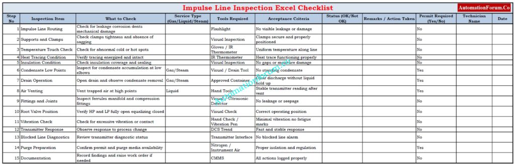
This Excel checklist is meant to help with regular impulse line inspections for DP pressure and flow transmitters. It helps technicians keep track of what they find, make sure they follow SOP rules, and keep measurements reliable.
You may get the full checklist here and utilise it:
How Regular Impulse Line Inspection Prevents False DP Readings
Following this step-by-step impulse line inspection approach very closely cuts down on false DP readings, sluggish response times, and unanticipated process problems. Adding this SOP to regular rounds makes ensuring that the instruments work properly, makes things safer, and cuts down on unscheduled maintenance.
Open Tank Level Calculator: Open Tank Level Transmitter Calculator – Complete Guide for EPC Instrumentation Engineers