- Introduction to Impulse Line Freezing Risk and Heat Tracing
- Impulse Line Freezing Risk and Heat Tracing Calculator
- Why Impulse Line Freezing Matters in Process Plants
- How the Impulse Line Freezing Calculator Helps Instrumentation Engineers
- Process Fluid Properties That Affect Freezing Risk
- Ambient Conditions That Increase Impulse Line Freezing
- Insulation Parameters for Impulse Line Freeze Protection
- Heat Tracing Configuration for Instrumentation Lines
- Engineering Calculation Logic Behind the Calculator
- Heat loss calculation for impulse lines
- Insulation resistance and thermal protection
- Wind correction factor for outdoor installations
- Time to freeze estimation
- Heat trace sizing with safety margin
- Safe freeze protection condition
- Moderate freeze risk condition
- Warning level freeze risk
- Critical impulse line freezing condition
- Symptoms of a Frozen Impulse Line
- Best Practices for EPC, Maintenance and Commissioning Teams
- Why Engineers Use This Calculator
- Who Should Use This Calculator
- Real World Use Case Study
- Symptoms of a Frozen Impulse Line
- Frequently Asked Questions About Impulse Line Freezing
- What is the purpose of the impulse line?
- What are impulse lines?
- What is the impulse line in a flow meter?
- What is the slope of impulse tubing?
- Why do impulse lines freeze?
- What is the best heat tracing method?
- How much insulation is required?
- What happens if a DP impulse line freezes?
- Why does wind increase freezing risk?
- Can steam tracing be used?
- What is the role of time to freeze?
- Why is stagnant fluid more vulnerable?
- What insulation is best for impulse lines?
- Why is a safety margin important?
Introduction to Impulse Line Freezing Risk and Heat Tracing
Impulse lines may look like a small part of an instrumentation system, but every engineer who has worked in cold weather service knows how important they are. These small bore tubes connect the process to pressure transmitters, differential pressure transmitters, and level measurement systems. When the line is healthy, the measurement is stable and reliable. When the line freezes, the signal can become wrong, delayed, blocked, or completely lost.
This is why impulse line freezing is a serious issue in process industries. A frozen line can lead to false readings, plugged sensing paths, transmitter errors, nuisance alarms, process trips, and unwanted shutdowns. In oil and gas plants, LNG facilities, refineries, chemical plants, power plants, and water treatment stations, this is not just a seasonal inconvenience. It is a real reliability problem that affects plant operation and maintenance.
The Impulse Line Freezing Risk and Heat Tracing Calculator is designed to help instrumentation professionals evaluate heat loss, insulation effectiveness, freezing risk, required heat tracing power, and time to freeze. It gives engineers a practical way to assess transmitter freeze protection before a problem reaches the field. The calculator is useful during design review, commissioning, maintenance planning, and winterization studies. It also helps teams compare tubing material, fluid properties, ambient conditions, insulation options, and heat tracing methods in one place.
Impulse Line Freezing Risk and Heat Tracing Calculator
⚡ Impulse Line Heat Tracing Calculator
Industrial Thermodynamic Simulation for Instrument Impulse Line Winterization
Tubing Details
Process Fluid Properties
Ambient Conditions
Insulation Parameters
Heat Tracing Configuration
Actions
Why Impulse Line Freezing Matters in Process Plants
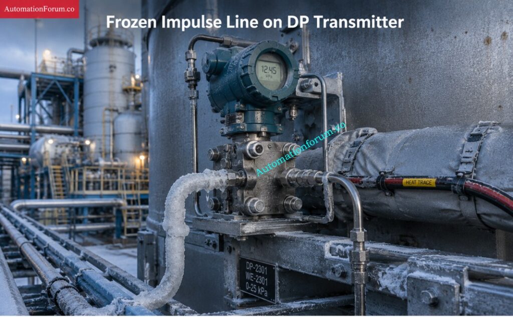
Impact on pressure transmitters and differential pressure transmitters
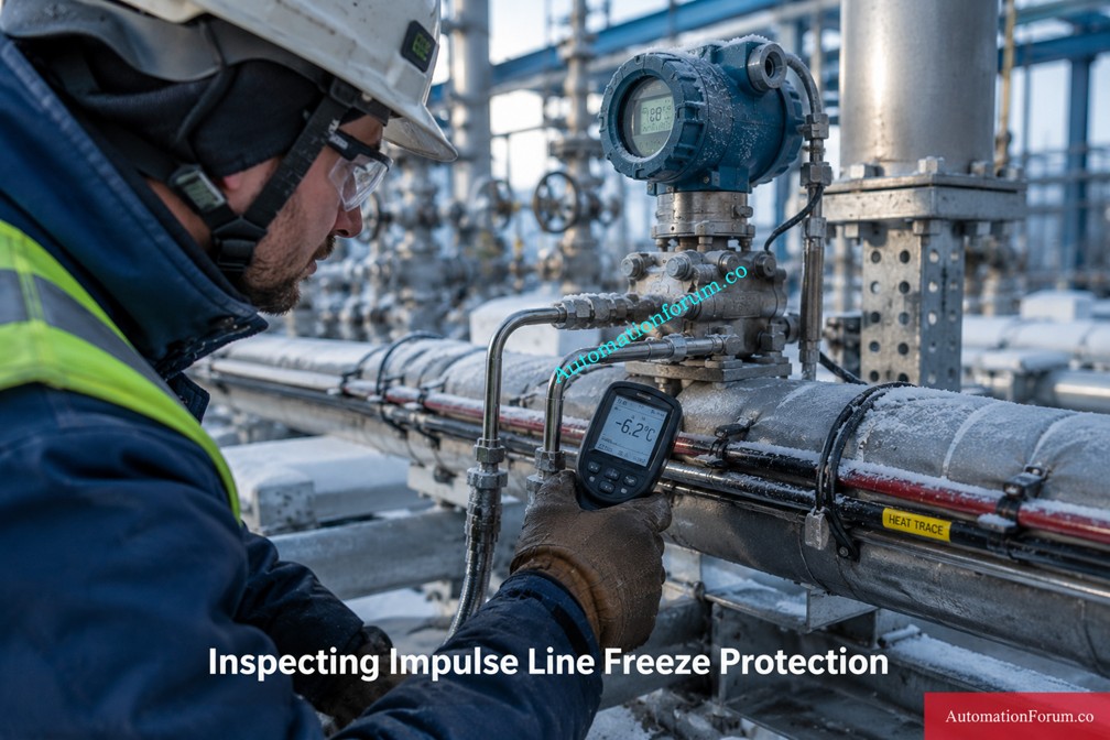
How frozen impulse lines cause false readings and shutdown risks
Importance of winterization in instrumentation systems
That is why winterization of instrumentation should always be part of good engineering practice. Insulation, electrical heat tracing, steam tracing, and proper routing all help protect the measurement system. The calculator supports that work by making freeze protection more measurable and more practical.
Master Impulse Line Installation Now: Advanced Quiz on Impulse Line Installation in Process Industries
How the Impulse Line Freezing Calculator Helps Instrumentation Engineers
Tubing details for freeze risk calculation
The tubing details section includes outer diameter, wall thickness, tubing length, and tubing material. These factors matter because they affect how fast heat is lost from the line. A longer line loses more heat. A thin wall has reduced thermal resistance. The higher the thermal conductivity of a material , the faster it will conduct heat .
This is why stainless steel tubing and copper tubing do not behave the same way in cold service. Stainless steel is much more common in instrumentation work, but copper has very different thermal behavior. The calculator helps the engineer compare these differences in a simple and practical way.
Inspect DP Transmitters Step By Step: Impulse Line Inspection Step By Step Procedure For DP Transmitters
Process Fluid Properties That Affect Freezing Risk
The process fluid section includes freezing point, density, specific heat, initial process temperature, and operating condition. These inputs are important because the same ambient temperature does not affect every fluid in the same way. Water, condensate, steam condensate, hydrocarbons, and glycol all behave differently.
Stagnant fluid freezes faster than flowing fluid because there is no movement to replace cooled fluid with warmer fluid from the process. This is a key point in impulse line freezing risk. The calculator reflects that reality by letting the engineer define the operating condition.
Pick the Perfect Impulse Tube Size: How to Select the Right Impulse Tube Size for Pressure Measurement Systems
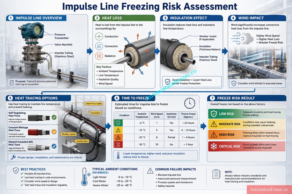
Ambient Conditions That Increase Impulse Line Freezing
Ambient temperature is the most obvious freeze factor, but wind speed is often just as important. Wind increases convective heat loss and can reduce the available thermal margin very quickly. That is why a line that looks safe on a calm day may become risky during windy weather.
Humidity and elevation also help define the local environment more accurately. In practical field work, the freezing problem usually comes from the combination of ambient temperature, exposure, and wind, not from one factor alone.
Refer the below link for the Method Statement for Pressure Test and leak Test for Instrument Tubing and Impulse line
Insulation Parameters for Impulse Line Freeze Protection
Insulation is one of the strongest defenses against freeze damage. The calculator allows the engineer to choose insulation material and thickness so the impact on heat loss can be compared. Mineral wool, polyurethane, calcium silicate, aerogel, and fiberglass all have different thermal characteristics.
Good insulation can increase time to freeze and reduce the load on the heat tracing system. Poor insulation, or insulation with gaps and moisture ingress, can do the opposite. That is why insulation selection and installation are both important.
Follow These Impulse Tubing Best Practices: Best Practices for Impulse Tubing Installation
Heat Tracing Configuration for Instrumentation Lines
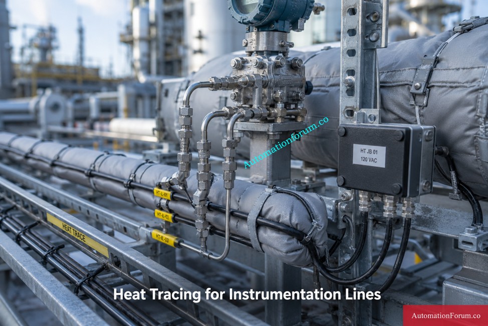
The heat tracing section supports electrical self regulating cable, constant wattage cable, steam tracing, and no heat tracing. It also includes trace rating, number of parallel traces, and supply voltage. These inputs help the engineer estimate whether the available heat input is enough to offset the heat loss from the impulse line.
Self regulating cable is often preferred in instrumentation applications because it can adjust output with temperature. Steam tracing can also work well in certain facilities, but it requires good maintenance and process discipline. The calculator gives engineers a way to review the options in a practical freeze protection context.
Get the Top Impulse Line Answers: Instrument Impulse Line: Most Common Questions and answers
Engineering Calculation Logic Behind the Calculator
Heat loss calculation for impulse lines
The calculator uses radial heat transfer logic to estimate heat loss from the impulse line. Heat loss rises when the temperature difference between the line and the surroundings increases. It also rises when the tube is longer or the material allows heat to move out more easily.
This is the basic reason impulse lines freeze. The line loses more heat than the process can replace. Once that happens, the fluid temperature drops and freeze risk begins to rise.
Insulation resistance and thermal protection
Insulation works by adding thermal resistance between the tube and the environment. Higher resistance means lower heat loss. In field terms, a better insulation layer gives the impulse line more time before it reaches freezing conditions.
That extra time matters. It gives the operator more margin, the maintenance team more response time, and the transmitter a better chance of staying reliable during cold weather.
Fix Impulse Line Problems Fast: What are Impulse lines? – Impulse line problems and solutions
Wind correction factor for outdoor installations
Wind can change the result very quickly because it strips heat away from the tubing and insulation surface. The calculator includes a wind correction factor so outdoor installations are evaluated more realistically.
This is especially useful for pipe racks, open structures, exposed transmitter stands, and other locations where the line is not sheltered from the weather.
Time to freeze estimation
Time to freeze is one of the most useful outputs in the calculator. It tells the engineer how long the line can remain above freezing before thermal energy is exhausted. This gives a practical measure of how urgent the freeze protection problem is.
If the time to freeze is short, the line needs stronger protection or faster intervention. If the time is long, the current design may be acceptable. For plant reliability work, this is a very useful number.
Heat trace sizing with safety margin
The calculator compares required heat trace power with available trace power and applies a safety margin. This is a simple but important step because freeze protection must cover not only the calculated heat loss, but also real field variation, installation tolerance, and aging effects.
In practice, engineers should never design a heat tracing system with zero margin. A proper margin gives more reliable operation during severe weather and protects the line if conditions become worse than expected.
Know Filled Versus Purged Impulse Lines: Difference between filled impulse line and purged impulse line
Freeze Risk Classification Results
Safe freeze protection condition
Safe means the line has enough thermal protection and enough time before freezing becomes a concern. This is the preferred operating condition for a winterized instrumentation system.
Moderate freeze risk condition
Moderate means the design is workable, but the safety margin is limited. In this circumstance the engineer should check insulation thickness, trace power and exposure conditions.
Warning level freeze risk
Warning indicates a substantial risk of freezing. The line may still work for now, but the protection system is close to its limit and should be reviewed quickly.
Detect Plugged Impulse Lines Quickly: Plugged Impulse Line Detection Impulse-line Purging & Close Coupling
Critical impulse line freezing condition
Critical means immediate action is required. The line may freeze very quickly or the heat tracing may be too weak to provide reliable protection. This is the most dangerous condition because the measurement can fail with little warning.
Symptoms of a Frozen Impulse Line
Common signs of impulse line freezing
Frozen impulse lines can create pressure transmitter plugging, false low level trips, frozen condensate, hydrocarbon waxing, blocked pressure sensing, steam condensate freezing, cracked tubing, and instrument shutdowns. In many plants, these problems are first seen during night shifts, cold starts, or troubleshooting after an unexpected alarm.
The real issue is not only the freeze itself. The larger issue is the loss of measurement trust. Once a sensing line becomes unreliable, operators may hesitate, control loops may drift, and shutdowns may follow. This is why impulse line insulation and heat tracing are such important parts of process instrumentation maintenance.
Crack EPC Interview Questions Today: Instrumentation Designer Interview Questions and Answers for EPC Projects
Best Practices for EPC, Maintenance and Commissioning Teams

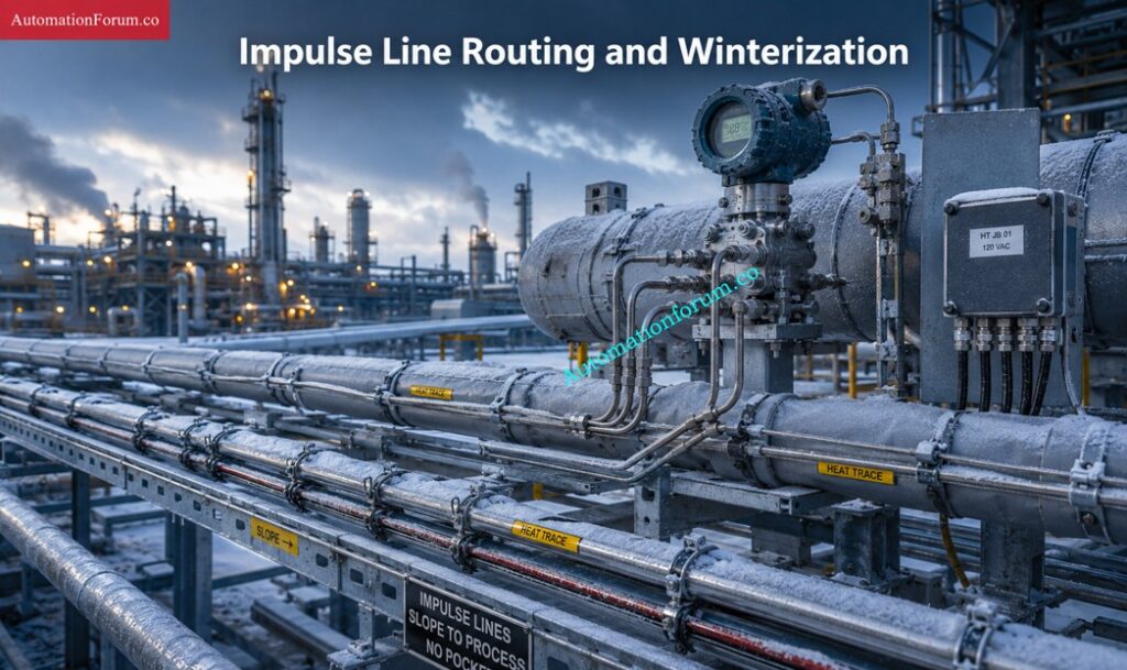
Proper tubing slope and routing
Impulse lines should be routed with proper slope and minimal dead legs. If the routing is poor, fluids can become trapped and be more likely to freeze. And good routing increases drainage too, and access for maintenance.
Insulation sealing and waterproofing
Insulation must be kept dry to perform effectively. Sealed joints and waterproofing, especially appropriate jacketing, are important. Wet insulation loses effectiveness and can shorten the life of the freeze protection system.
Heat trace continuity checks and megger testing
Heat trace continuity testing and megger testing should be part of commissioning and routine maintenance. If the trace cable fails, the line may freeze even though the installation looks correct from the outside.
Know the DCS FAT Procedure: Factory Acceptance Test Procedure for Distributed Control System DCS
Thermographic inspection for cold spots
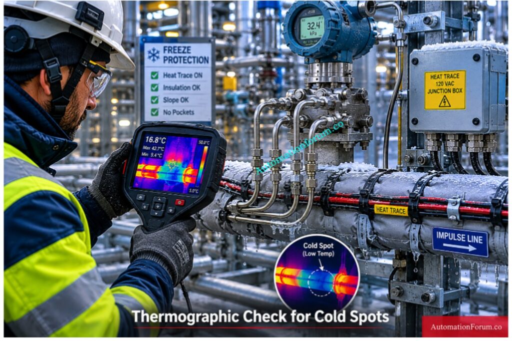
Thermography is a useful field tool because it helps identify cold spots, failed sections, or uneven heating. It is one of the easiest ways to verify that the freeze protection system is working properly.
Steam trap inspection for steam tracing systems
If steam tracing is used, steam trap inspection is critical. A failed trap can reduce heating performance and create a false sense of protection. Regular maintenance matters here.
Inspect Analyzer Systems the Right Way: Running Inspection Procedure for Analyzer and Sampling System in Process Industries
Why Engineers Use This Calculator
This calculator helps reduce uncertainty. Instead of guessing, the engineer can enter real values for tubing size, material, fluid behavior, ambient conditions, wind speed, insulation thickness, and heat tracing power. That makes the result much more useful for design review and maintenance planning.
It is especially helpful during EPC design review, winterization studies, commissioning verification, shutdown prevention, energy optimization, and predictive maintenance. It also gives different teams a common engineering reference, which makes decisions easier and faster.
Install and Remove DP Transmitters Safely: Step-by-Step Guide: Installing & Removing a DP Transmitter with a 5-Way Valve Manifold
Who Should Use This Calculator
This calculator is useful for instrumentation engineers, process engineers, maintenance teams, reliability engineers, EPC contractors, commissioning teams, plant operators and engineering students. It is useful for those working in transmitter freeze protection, impulse line insulation or process instrumentation maintenance.
Commission DP Transmitters Without Mistakes: Safe Commissioning & Removal of DP Transmitters with a 3-Way Valve Manifold
Real World Use Case Study
Case Study 1: Frozen DP Transmitter Impulse Line in a Refinery
On a frigid morning shift, a refinery maintenance crew was troubleshooting an unreliable differential pressure transmitter on a process vessel. The transmitter was utilized for level indication and the reading had started to drift lower than normal. The operators originally suspected an issue with the transmitter but the instrument check proved that the transmitter itself was healthy. The actual problem was traced to the impulse line.
The sensing line was installed outdoors with limited insulation, and the route had a small low point where condensate collected. Overnight ambient temperature dropped below freezing, and wind exposure increased the heat loss from the tubing. The line sat still, and the liquids inside it cooled quickly. The outcome was partial freezing in the impulse line, which blocked the pressure signal and gave a misleading low-level reading.
The maintenance team reviewed the conditions of the line with the impulse line freezing risk and heat tracing calculator. They entered the tube size, wall thickness, length of the line, parameters of the fluid, ambient temperature, wind speed, insulation thickness and heat trace rating. The calculator indicated that the heat loss was greater than anticipated and the available heat tracing power was borderline for the weather circumstances. It also showed a short time to freeze, which was what the plant was observing in the field.
The corrective actions were simple and pragmatic. The crew increased the insulation, rectified the slope of the tubing, removed the low point and checked the continuity of the heat trace. After the work, the transmitter response became stable again and the freeze risk moved back into the safe range. This case showed that a transmitter problem is often actually a winterization problem.
Zero DP Transmitters the Safe Way: How to Safely Zero a DP Transmitter with 3-Way Valve and 5-Way Valve Manifolds.
Case Study 2: Steam Condensate Freezing in a Power Plant
The engineering team assessed the installation and determined that the line had sufficient heat tracing on paper, but insufficient practical freeze protection in the field. They used the calculator to compare heat loss with and without insulation and to estimate the time to freeze under the actual ambient conditions. The result showed that the line needed additional freeze protection margin. The team then upgraded insulation, improved weather sealing, and increased attention to trace cable verification during commissioning.
This kind of situation is very common in process instrumentation maintenance. The line may look fine during inspection, but if moisture, wind, and low ambient temperature combine, the thermal margin disappears quickly. The calculator is useful because it helps engineers see that risk before the plant experiences a measurement failure.
Choose the Right Pressure Manifold Fast: Key Considerations for Pressure Transmitter Manifold Selection
Symptoms of a Frozen Impulse Line
Common signs of impulse line freezing
A frozen impulse line often shows up as one or more of these symptoms:
A transmitter reading that suddenly drifts or stays fixed even though the process is changing.
A differential pressure signal that appears too low, too high, or unstable.
A level indication that does not match the actual vessel condition.
Slow response of the transmitter after a chilly night
Alarms or trip circumstances that occur frequently but clear up as the line thaws.
These symptoms usually point to a freeze protection issue rather than a bad transmitter. In many cases, the instrument is only reporting what the blocked line allows it to see.
Understand Instrumentation Manifolds Clearly: What is manifold and types of manifolds and application of manifolds in Instrumentation?
Frequently Asked Questions About Impulse Line Freezing
What is the purpose of the impulse line?
It connects the process tapping point to the instrument and transmits pressure safely and accurately.
It also helps isolate, stabilize, and protect the transmitter from direct process conditions.
What are impulse lines?
Impulse lines are small bore tubes used in instrumentation to carry process pressure from the plant line to a pressure instrument.
They are commonly used with pressure transmitters, DP transmitters, and level measurement systems.
What is the impulse line in a flow meter?
In a flow meter, the impulse line carries pressure from the process or from upstream and downstream tapping points to the differential pressure transmitter.
It allows the transmitter to measure pressure difference and calculate flow.
What is the slope of impulse tubing?
Impulse tubing is normally installed with a proper slope to prevent air pockets, liquid traps, and condensate buildup.
The exact slope depends on the service, but it should always allow drainage and stable measurement.
Why do impulse lines freeze?
Impulse lines freeze because they lose heat to the environment, and stagnant fluid inside the line cools faster than the process can replace it.
What is the best heat tracing method?
The best method depends on the service, but self regulating electrical heat tracing is often used because it is practical and easy to apply.
How much insulation is required?
It depends on ambient temperature, wind speed, type of fluid, line length and the degree of freeze protection required.
What happens if a DP impulse line freezes?
The reading can be inaccurate, delayed, obstructed or unstable. This may compromise control and safety operation.
Why does wind increase freezing risk?
The wind enhances convective heat loss and accelerates the heat loss from the tubing surface.
Can steam tracing be used?
Yes, but it must be designed and maintained carefully to stay effective.
What is the role of time to freeze?
Time to freeze is how long the line can stay above freezing before protection is needed.
Why is stagnant fluid more vulnerable?
Because it has no warmer fluid from the process to replace it.
What insulation is best for impulse lines?
Best insulation relies on application, temperature range, cost and maintenance expectations.
Why is a safety margin important?
Since field circumstances are seldom perfect and the system needs more capacity for reliability.
Use Valve Manifolds Correctly: What are the uses of Valve manifolds?
Impulse line freezing is a real engineering problem, not a minor seasonal issue. A short length of tubing can affect measurement accuracy, process stability, and plant safety. That is why winterization of instrumentation should always include insulation, heat tracing, and a proper freeze protection review.
This calculator gives instrumentation professionals a practical way to evaluate heat loss, insulation effectiveness, time to freeze, and trace sizing before the problem reaches the field. It is a useful tool for design, commissioning, maintenance, and troubleshooting, and it supports better decisions for reliable process operation in cold weather service.
Refer the below link – Key Considerations for Pressure Transmitter Manifold Selection