
- What Is a Maintenance Override Switch?
- Why Is a Maintenance Override Switch Used?
- Maintenance Override Switch Applications in Process Industries
- How Does a Maintenance Override Switch Work?
- How Is a Maintenance Override Switch Implemented?
- How Does Maintenance Override Switch Logic Work?
- Maintenance Override Switch and Safety Instrumented Functions
- Maintenance Override Switch Versus Bypass
- Maintenance Override Switch Panel Design
- Maintenance Override Switch and Cause and Effect
- Maintenance Override Switch HMI Indication
- Maintenance Override Switch Practical Example
- Maintenance Override Switch Troubleshooting
- Common Maintenance Override Switch Mistakes
- Maintenance Override Switch Management
- Maintenance Override Switch Design Checklist
- Frequently Asked Questions About Maintenance Override Switch
- Conclusion: Why Proper Maintenance Override Management Matters
A Maintenance Override Switch, commonly called MOS, is an important facility in process industry safety systems. It allows a selected safety signal to be temporarily overridden when an instrument requires maintenance, calibration, testing, or replacement.
What Is a Maintenance Override Switch?
Maintenance Override Switch Definition
A Maintenance Override Switch is a controlled mechanism used to temporarily prevent a selected safety instrument signal from initiating its normal safety action.
Purpose of a Maintenance Override Switch
For example, a pressure transmitter may be part of a high pressure shutdown function. When the transmitter is removed for calibration, its signal may change to a condition that would normally initiate an ESD trip. An approved MOS can temporarily inhibit that particular trip while the transmitter is under maintenance.
How a Maintenance Override Switch Works
Why MOS Is Different From a Normal Selector Switch
A MOS should never be considered an ordinary selector switch. It is part of the safety management philosophy and must be designed around the approved safety requirements, cause and effect documentation, and operating procedures.
Refer the below link for the 2oo3 Voting Logic Explained: How it Works, Why it is Used and Where it Applies
Why Is a Maintenance Override Switch Used?
Maintenance activities frequently require safety instruments to be temporarily taken out of service.
Typical examples include:
- Pressure transmitter calibration
- Level transmitter replacement
- Fire and gas detector maintenance
- Pressure switch testing
- Shutdown valve testing
- SIS proof testing
- Instrument loop troubleshooting
- Transmitter replacement
- Detector inspection
- Final element maintenance
Without an approved override facility, maintenance personnel may face a choice between causing an unwanted shutdown or using an informal method to prevent the trip. Informal wiring changes and uncontrolled forcing create significant risk because the temporary condition can be forgotten or incorrectly restored.
Discover how engineers select reliable ESD trip signals: How are ESD Signals Selected? Complete ESD Signal Selection Guide
Maintenance Override Switch Applications in Process Industries
Maintenance Override Switches can be encountered in refineries, petrochemical plants, gas processing facilities, LNG plants, offshore platforms, compressor stations, tank farms, production facilities, and other process installations.
Common applications include:
| Safety function | Typical maintenance situation |
| High pressure trip | Pressure transmitter calibration |
| High level trip | Level instrument maintenance |
| Low flow trip | Flow transmitter testing |
| High temperature trip | Temperature transmitter replacement |
| Emergency shutdown valve | Valve maintenance or testing |
| Fire and gas detector | Detector inspection |
| Compressor shutdown | Instrument testing |
| Pump shutdown | Protection loop maintenance |
The exact application depends on the process hazard, SIF design, available safeguards, process dynamics, and project safety philosophy.
Understand the safety concepts behind modern SIS engineering: Process Safety vs Functional Safety: Key Differences, SIS, SIF, SIL & IEC 61511 Guide
How Does a Maintenance Override Switch Work?
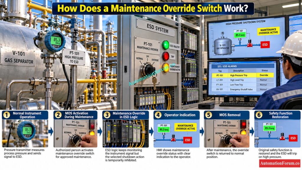
Normal Instrument Operation
Under normal plant operation, the instrument signal is continuously monitored by the ESD or SIS logic solver. The field instrument provides the process condition, and the safety logic determines whether the configured trip condition has occurred.
For example, a high pressure transmitter may provide a process signal to the SIS. When the pressure reaches the configured trip level, the safety logic generates the required shutdown action.
During normal operation, the Maintenance Override Switch remains in its normal position and has no effect on the safety function. The complete signal path remains available for detecting the hazardous condition and initiating the required protective action.
Select the right barrier before hazardous area installation: Intrinsic Safety Barrier Selection Procedure for Instrumentation Engineers
MOS Activation During Maintenance
When an instrument requires calibration, inspection, replacement, or testing, the approved maintenance procedure may require a temporary maintenance override.
The important point is that the override should apply only to the intended safety function. It should not unintentionally affect other independent trips, shutdown functions, alarms, or protective layers.
Separate process safety from functional safety correctly: Process Safety vs Functional Safety: Key Differences, SIS, SIF, SIL & IEC 61511 Guide
Maintenance Override in ESD Logic
After the MOS is activated, the ESD or SIS logic recognizes the override status and processes the affected safety signal according to the approved logic design.
Conceptually, a maintenance override can be represented as:
Trip Action = Unsafe Condition AND NOT Maintenance Override
This means the selected trip action is prevented while the approved maintenance override is active.
This expression is only a conceptual representation. Actual ESD and SIS logic can be considerably more complex because of voting arrangements, permissives, interlocks, bypass conditions, reset logic, and fail safe requirements.
The actual implementation must always follow the approved Cause and Effect, safety requirements specification, logic diagrams, and project safety philosophy.
Verify safety integrity before final project approval: SIL Verification Report (Safety Integrity Level Verification Report)
Operator Indication During MOS Activation
A maintenance override should never become invisible to the operator.
When MOS is active, the operator should receive a clear indication showing which instrument or safety function has been overridden. Depending on the system design, this may include a local switch indication, ESD panel indication, HMI indication, alarm, status message, or bypass summary.
The indication should enable the operator to see the current protection status without having to look at the physical MOS panel.
For essential safety functions, the indication should clearly indicate the impacted tag and offer sufficient information to allow the operator to realize that the regular safety protection is temporarily absent or modified.
Prevent PLC I O failures before they cause downtime: Proactive Maintenance Strategies for PLC I/O Modules: Reduce Downtime & Improve Reliability
Removing the Maintenance Override
After the maintenance activity is completed, the MOS must be purposefully removed as per the approved restoration technique.
Before removal of the override, the maintenance crew should ensure that the instrument has been properly installed, calibrated, linked, tested and put back into service.
Check the physical switch position, ESD or SIS logic status, HMI indication and field instrument condition to prevent restoration to the wrong position.
Removing the MOS without confirming the instrument condition can create an unsafe situation because the safety logic may suddenly depend on an instrument that has not yet been properly returned to service.
Learn the right way to manage safety overrides: IEC 61511 Safety Bypass And Override in Instrumentation and Control System Maintenance
Restoring the Original Safety Function
The final stage is restoration of the complete safety function.
After the MOS is removed, the ESD or SIS should again respond to the instrument according to its original approved logic. The maintenance team should verify the input signal, logic response, operator indication, alarm status, and final element response where applicable.
The restoration should be recorded in the appropriate maintenance or bypass register, with the responsible personnel confirming that the safety function is fully available.
A good MOS procedure therefore does not end when the maintenance work is completed. It ends only after the original safety function has been verified and formally returned to normal operation.
Refer the below link for the ESD vs PSD: Difference Between Emergency Shutdown System and Process Shutdown System
How Is a Maintenance Override Switch Implemented?
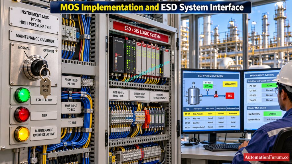
Hardware Maintenance Override Switch
A hardware MOS is typically provided through a dedicated switch or key operated arrangement associated with a specific safety function or instrument.
The switch should be clearly identified with the relevant instrument tag and safety function so that the operator cannot easily select the wrong override.
Depending on the project philosophy, the switch may provide electrical contacts that are connected to the ESD or SIS input and processed by the approved safety logic.
Prepare for challenging SIS interviews with confidence: Safety Instrumented System(SIS) Interview Questions and Answers
HMI Based Maintenance Override
Some modern systems provide maintenance override functions through an HMI or engineering interface rather than using only physical switches.
See how emergency block valves protect critical processes: What is an Emergency Block valve and How does it work
Master MOS Enable Switch
A master MOS enable arrangement can provide an additional level of control over individual maintenance overrides.
The master enable function can be used to ensure that individual MOS selections cannot be activated accidentally during normal plant operation.
The exact arrangement depends on the project safety philosophy and should be defined in the approved safety logic documentation.
Individual Instrument Override
Individual MOS functions allow a specific instrument or safety function to be placed into maintenance override without unnecessarily affecting other safety functions.
Each override should have a clearly defined relationship with its associated instrument tag and safety function.
This technique helps to decrease the potential of inadvertently overriding some other trip, and makes the active maintenance condition more readily recognized by operators and maintenance people.
MOS Interface With ESD System
The MOS interface connects the maintenance override command with the ESD or SIS logic.
The engineering design must verify the complete signal path from the physical switch or HMI command through the input interface and logic solver to the intended safety function.
During commissioning, the team should confirm that activating one MOS affects only the intended logic and that the correct operator indication is generated.
MOS Access Control
Because a maintenance override can temporarily reduce a safety function, access control is an important part of MOS implementation.
Check your SIS design against critical compliance requirements: Advanced Safety Instrumented System (SIS) Inspection Checklist for IEC 61511 Compliance
How Does Maintenance Override Switch Logic Work?
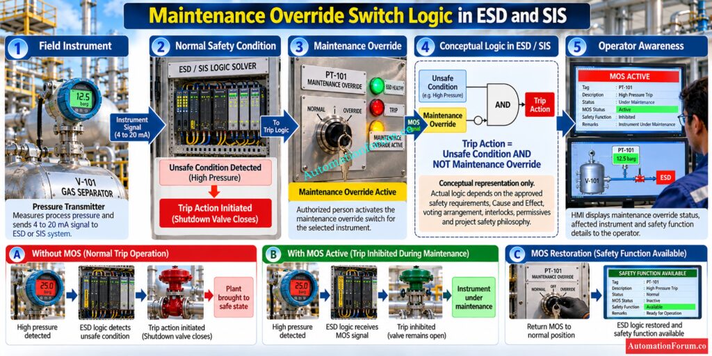
Normal Safety Signal
The safety instrument transmits its process signal to the ESD or SIS during normal operation. The safety logic constantly compares this signal to the set trip criteria.
When the process reaches an unsafe condition, the logic solver generates the required safety action.
The MOS remains inactive, so the normal safety function remains available.
Maintenance Override Condition
The logic then treats the affected safety input according to the approved override philosophy.
The override should be specific, controlled, and traceable. It should not create an unrestricted ability to disable safety logic.
Trip Inhibition
The primary purpose of the MOS logic is normally to prevent the selected maintenance activity from causing an unwanted safety action while the instrument is being worked on.
Conceptually:
Trip Action = Unsafe Condition AND NOT Maintenance Override
When the maintenance override is active, the selected trip action is inhibited according to the approved logic.
However, the logic must be carefully designed so that other independent protection functions remain available wherever required.
MOS Status Indication
The ESD or SIS should recognize the active MOS condition and provide an appropriate status indication.
The indication should identify the affected instrument or safety function rather than simply displaying a general maintenance message.
This allows the control room operator to understand exactly which safety protection has been temporarily modified.
MOS Alarm Handling
An active maintenance override may require an alarm or dedicated status indication depending on the project safety philosophy.
The purpose is to make the temporary reduction in safety protection visible to the operating team.
Alarm handling should also consider what happens when the MOS is removed, including clearing of the alarm, restoration of normal status, and confirmation that no override remains active unintentionally.
MOS Logic and Voting Arrangement
MOS logic must be carefully considered when the affected safety function uses voting logic such as 1oo2, 2oo3, or other architectures.
For example, overriding one instrument in a voting arrangement can change the effective protection available from the remaining instruments.
The engineering review should therefore determine whether the MOS changes the voting behavior, reduces redundancy, changes the trip availability, or requires additional operating restrictions.
The effect should be defined in the approved safety logic and Cause and Effect documentation rather than assumed during maintenance.
MOS Logic and Fail Safe Operation
The MOS arrangement should be reviewed together with the fail safe philosophy of the ESD or SIS.
A failure of the MOS switch, wiring, input module, communication path, or logic configuration should not unintentionally create an uncontrolled maintenance override.
The design should consider what happens if the MOS signal is lost, stuck, incorrectly wired, or falsely indicated.
Avoid these costly mistakes in safety system design: Top Critical Mistakes in Safety Instrumented System Design as per ISA 84 Standard and How to Avoid Them
Maintenance Override Switch and Safety Instrumented Functions
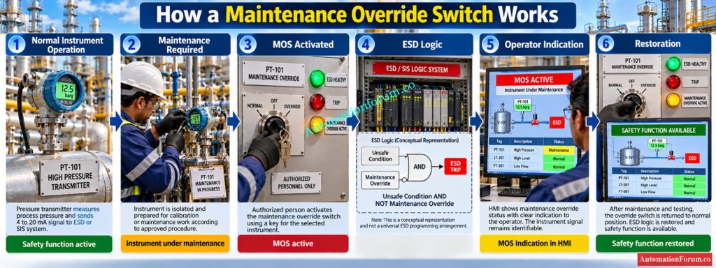
A Safety Instrumented Function consists of sensors, a logic solver, and final elements performing a defined safety action.
Activating a maintenance override can temporarily reduce the protection available from that SIF. Therefore, the risk cannot be judged only by looking at the switch itself.
The plant should consider:
- The reason for the override
- The duration
- The affected SIF
- Available independent safeguards
- Compensating measures
- Process operating conditions
- Operator awareness
- Restoration requirements
IEC 61511 specifically addresses SIS operation and maintenance as part of the functional safety lifecycle.
A MOS does not automatically make a plant unsafe. The risk depends on how the override is engineered and managed.
Learn why transmitter redundancy matters for process safety: Redundant Transmitters Explained: Reliability, Voting Logic and SIL for Instrumentation Engineers
Maintenance Override Switch Versus Bypass
| Method | Typical purpose | Control concern |
| MOS | Controlled maintenance override | Requires authorization and status monitoring |
| Manual bypass | Temporary physical bypass | Risk of incorrect restoration |
| Software bypass | Logic based bypass | Requires access control and logging |
| Logic override | Configured safety logic function | Requires validated logic |
| Interlock bypass | Temporary inhibition of an interlock | Can affect equipment protection |
| SIS bypass | Temporary removal of a safety function | Requires strong risk controls |
| ESD bypass | Temporary inhibition of an ESD action | Can reduce shutdown protection |
Know exactly when ESD or SIS should apply: ESD vs SIS Difference When to Use Each and Practical Engineering Guide
Maintenance Override Switch Panel Design
A MOS panel should be designed according to the project safety philosophy and electrical and instrumentation requirements.
Important considerations include:
- Clear instrument identification
- Appropriate switch type
- Key operated access where required
- Clear status indication
- HMI indication
- Alarm indication
- Electrical segregation
- Suitable panel location
- Proper cable design
- Testing provisions
- Environmental suitability
- Hazardous area requirements where applicable
- Controlled access
- Documented restoration procedure
Some project specifications use a master MOS enable facility before individual overrides can be activated. This creates an additional administrative and physical control layer.
Master the fundamentals every functional safety engineer needs: What is SIS, SIF and SIL? An In-Depth Guide to Functional Safety in Process Industries
Maintenance Override Switch and Cause and Effect
The ESD cause and effect document should clearly establish the relationship between the safety input, override condition, logic action, and final element response.
For example:
| Condition | ESD response |
| High pressure detected | Shutdown initiated |
| High pressure under approved MOS | Defined trip action inhibited |
| MOS active | Operator indication generated |
| Maintenance complete | MOS removed |
| Restoration verified | Normal trip protection available |
The final implementation must match the approved logic diagram, cause and effect matrix, application program, and commissioning test records.
Calculate SIL performance before approving your safety function: SIF PFDavg / SIL Verification – Complete Guide + Online Calculator (IEC 61508 / 61511)
Maintenance Override Switch HMI Indication
One of the most important requirements is operator awareness.
The control room should be able to identify the affected instrument or SIF, its override status, and relevant alarm or maintenance information.
Understand how repair delays can affect safety protection: Testing and Repair Deferral – IEC Guidelines, Procedure, and Best Practices
Maintenance Override Switch Practical Example
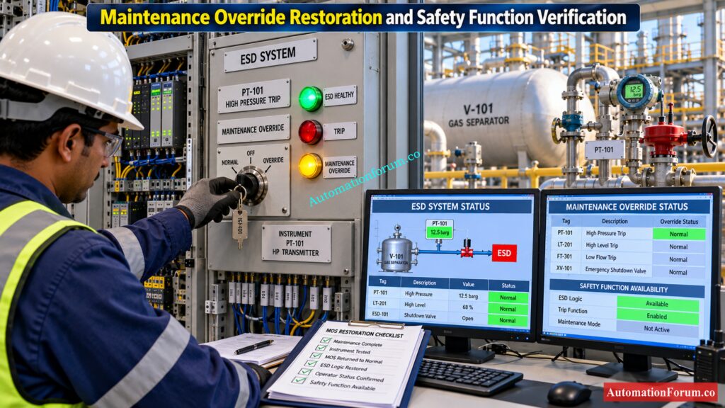
Assume a gas separator has a high pressure shutdown function using a pressure transmitter connected to the ESD system.
During normal operation, high pressure causes the ESD system to close the required shutdown valve.
The transmitter is scheduled for calibration.
The selected MOS is activated.
The ESD system identifies the transmitter as being under maintenance override while the operator receives the corresponding indication.
The transmitter is removed and calibrated.
The instrument is reinstalled and tested.
The override is removed.
The safety function is checked and the operator confirms normal status.
Only after restoration has been verified should the maintenance activity be considered complete.
This approach keeps maintenance activity connected to the overall process safety management system rather than treating the MOS as simply an electrical switch.
Build your functional safety vocabulary with this resource: Functional Safety Terminology – Excel Download for Industrial Automation
Maintenance Override Switch Troubleshooting
When a MOS does not behave as expected, troubleshooting should begin with documentation rather than immediately changing wiring or forcing signals.
Check the following sequence:
- Confirm the correct instrument tag
- Verify the intended SIF
- Check the physical switch status
- Check the ESD input status
- Verify I/O mapping
- Check the configured override status
- Check HMI indication
- Check alarm handling
- Compare the implemented logic with the approved cause and effect
- Check wiring and termination
- Verify restoration after correction
Typical problems include an activated MOS with missing HMI indication, incorrect tag mapping, faulty switch contacts, wiring problems, incorrect logic configuration, or a mismatch between the physical switch and ESD status.
Never bypass another safety function simply to troubleshoot an existing override problem.
Identify the signals that trigger critical valve shutdown: Signals for Emergency Valve Shutdown in Critical Processes
Common Maintenance Override Switch Mistakes
Another common problem occurs when maintenance personnel complete the physical work but the override remains active. This can leave the plant operating with reduced protection without anyone realizing it.
The solution is not merely better instrumentation. It requires a disciplined bypass management process involving operations, maintenance, instrumentation, and process safety personnel.
Test your SIS knowledge before your next project: Test Your Expertise in Safety Instrumented Systems (SIS): Knowledge Quiz
Maintenance Override Switch Management
The bypass should be recorded and reviewed until it is removed.
IEC 61511 is particularly relevant because it establishes lifecycle requirements for SIS specification, design, installation, operation, and maintenance. ISA 84 provides the corresponding functional safety framework for instrumented systems in process industries.
The exact MOS hardware arrangement is project specific. The standards should not be interpreted as requiring one particular switch or panel arrangement in every plant.
Understand the engineering documents behind automation architecture: Vendor Document for Project Systems Architecture: Complete Engineering Guide for Instrumentation, Automation and Control
Maintenance Override Switch Design Checklist
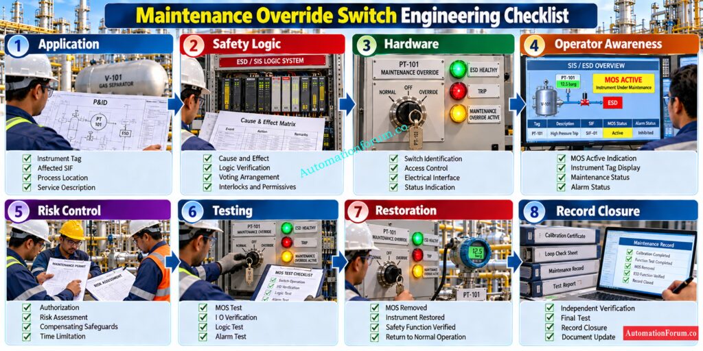
| Check | Detailed Requirement |
| Application | Clearly define why the Maintenance Override Switch is required and identify the specific maintenance activity it supports. |
| SIF Identification | Identify the specific Safety Instrumented Function affected by the MOS and verify the relevant instrument tag. |
| Safety Function | Check which protection function is briefly disabled when the MOS is triggered, and which is still functioning. |
| Cause and Effect | Ensure the approved ESD cause and effect documentation reflects the MOS behavior accurately. |
| Logic | Ensure that the maintenance override logic is evaluated and approved before implementation. |
| Voting Logic | If more than one transmitter or switch is utilized, check the effect of the MOS on the suitable voting configuration. |
| Hardware | Choose the right switch, contact layout, interface, and panel hardware according to the project requirements. |
| Access Control | Apply appropriate authorization or access control to avoid illegal activation of the MOS. |
| Switch Identification | Clearly identify each MOS with the proper instrument tag and service description and safety function. |
| Indication | Provide clear local indication showing whether the MOS is active or inactive. |
| HMI Indication | Display the active MOS status clearly on the operator HMI or approved control interface. |
| Alarm | Provide appropriate alarm or notification when a maintenance override is active where required by the project philosophy. |
| Logic Indication | Confirm that the ESD or SIS logic correctly recognizes the active MOS condition. |
| Documentation | Ensure the MOS is correctly shown in logic diagrams, cause and effect documents, panel drawings, and relevant engineering documents. |
| Bypass Register | Record the affected instrument, reason for override, authorization, activation time, and restoration status. |
| Testing | Test MOS activation, logic response, indication, alarm behavior, and restoration during commissioning. |
| Field Verification | Confirm that the physical switch operation corresponds correctly with the intended ESD or SIS input. |
| I/O Verification | Verify correct I/O channel assignment, termination, signal status, and ESD logic mapping. |
| Risk Assessment | Evaluate the temporary loss of protection due to placing the safety function under maintenance override. |
| Compensating Safeguards | Specify any extra safeguards or operational limits that are required during the time the impacted protective function is unavailable. |
| Time Limitation | Specify the allowable length of the override and include a clear restoration criteria. |
| Operator Awareness | Make the operations personnel aware of the safety function being overridden and the operational constraints. |
| Maintenance Coordination | Provide interface between MOS activation and maintenance activities and the permit to work process. |
| Restoration | Following maintenance, remove the MOS and check that the original safety function has been fully restored. |
| Independent Verification | Where required, have another authorized person verify correct restoration and normal safety system status. |
| Final Test | Confirm that the original trip function operates correctly after the MOS has been removed. |
| Record Closure | Close the MOS record only after maintenance, testing, restoration, and verification are complete. |
Practical engineering point
The most important checks are not simply whether the MOS switch operates. The engineer should verify the complete chain from physical MOS activation to ESD logic, operator indication, alarm status, maintenance activity, removal of the override, and final restoration of the safety function.
Define shutdown requirements before starting detailed engineering: Shutdown Philosophy: Engineering Documentation for Process Safety and Emergency Shutdown Systems
Frequently Asked Questions About Maintenance Override Switch
What is a Maintenance Override Switch?
A Maintenance Override Switch is a controlled facility used to temporarily override a selected safety signal during approved maintenance activities.
It allows instrument maintenance while keeping the override controlled, visible, and properly documented.
What is MOS in ESD?
MOS in an ESD system temporarily inhibits a selected safety action according to the approved ESD logic.
The active override should remain clearly visible to the operator throughout the maintenance activity.
Why is MOS used in SIS?
MOS permits certain safety instruments to be serviced, checked or changed without a needless shutdown.
Is MOS the same as a bypass?
MOS is a controlled maintenance override facility used to temporarily inhibit a selected safety function.
Bypass is a broader term, and its implementation and meaning depend on the project safety philosophy.
Can MOS disable an ESD trip?
A MOS can temporarily inhibit a defined ESD action when the approved safety logic permits the override.
The exact behavior depends on the ESD design, cause and effect, and project requirements.
What happens when MOS is activated?
The selected safety input enters its approved maintenance override condition within the ESD or SIS logic.
The operator should receive clear indication that the associated protection function is under maintenance.
Where is MOS installed?
MOS may be provided on an ESD panel, control room console, hardwired panel, or approved control interface.
The physical arrangement depends on the ESD architecture and project engineering philosophy.
Can MOS affect SIL?
A temporary MOS can reduce the protection available from the affected Safety Instrumented Function.
Its effect must therefore be assessed and controlled rather than assuming that the SIL remains unchanged.
How is MOS tested?
MOS testing should verify switch operation, safety logic response, operator indication, alarm behavior, and restoration.
Testing should follow the approved commissioning, maintenance, and proof testing procedure.
What is an override switch?
What is the difference between override and bypass control?
An override temporarily changes the response of a selected function under defined conditions and controls.
Bypass generally refers to temporarily preventing a function from producing its normal action.
What does MOS stand for in safety systems?
In the industrial ESD and SIS world, MOS is often used as an acronym for Maintenance Override Switch .
Offers a regulated means of temporarily overriding chosen safety inputs for maintenance purposes.
What is the MOS full form?
The complete version of MOS in process industry safety systems is Maintenance Override Switch.
What does MOS stand for?
In ESD and process safety applications, MOS normally means Maintenance Override Switch.
It is used to place selected safety functions into an approved maintenance condition.
What is an example of a MOS?
A high pressure transmitter may have a MOS facility for calibration without causing an unwanted ESD trip.
The override remains indicated to the operator until the transmitter is restored and the MOS is removed.
How do I find my MOS?
In an industrial plant, the MOS is normally identified through the ESD drawings, cause and effect documents, panel drawings, or HMI.
The instrument tag and associated safety function should always be verified before operating it.
What is the difference between override and overload?
An override changes or inhibits the normal response of a selected control or safety function under defined conditions.
An overload is an excessive electrical, mechanical, or process load that exceeds the intended operating capacity.
Verify intrinsic safety compatibility before connecting field devices: Intrinsic Safety Entity Parameter Calculator for Reliable Hazardous Area Loop Design
Conclusion: Why Proper Maintenance Override Management Matters
A Maintenance Override Switch is a useful facility for maintaining process industry safety systems without unnecessary shutdowns. Its value comes from controlled engineering, not simply from the switch itself.
In an ESD or SIS environment, maintenance convenience must never replace process safety discipline. A well designed MOS system allows maintenance work to proceed while keeping the status of the affected protection function visible to everyone responsible for safe plant operation.
Refer the below link for the Understanding 2 out of 2 SOV: Working & Configuration
