- Introduction to Split Range Control
- What Is Split Range Control in Industrial Automation
- Why Split Range Control Is Used in Process Industries
- What Is a Split Range Calculator
- Who Uses This Split Range Calculator
- When to Use a Split Range Calculator
- Where Split Range Control Is Used
- Working Principle of Split Range Control
- Understanding Direct Acting and Reverse Acting Valves
- Understanding Overlap and Gap in Split Range Control
- Features of the Uploaded Split Range Calculator
- Industrial Applications of Split Range Control
- Engineering Formula Explanation
- Benefits of Using This Split Range Calculator
- Real Engineering Challenges in Split Range Control
- Best Practices for Split Range Control
- FAQ Section on Split Range Calculator
- Conclusion: How This Split Range Calculator Helps Engineers
Split Range Calculator
A practical engineering calculator for split range control, valve sequencing, overlap, gap, direct acting and reverse acting behavior, and controller output allocation used in PLC and DCS applications.
Controller Configuration
Valve Sequencing
Actions
Validation Messages
Calculated Output
Sequencing Map
Valve Status
Full Range Sequence Table
Engineering Interpretation
((CO - Start) / (Stop - Start)) × 100
Reverse acting valve opening:
((Stop - CO) / (Stop - Start)) × 100
Overlap:
previous stop − next start
Gap:
next start − previous stop
Application Note
Introduction to Split Range Control
Split range control is one of the most common control techniques used in industrial automation and process industries. It is utilized when one controller output has to control several control valves or final control elements in a controlled sequence. In many industrial processes, a single valve cannot offer reliable and efficient control over the whole operating range. So for this reason engineers split the controller output into distinct areas, so that each valve works in a certain part of the output signal. This method is called split range control.
The attached Split Range Calculator is designed to help instrumentation engineers, PLC programmers, DCS engineers, process control specialists, commissioning engineers, and industrial maintenance professionals easily configure and analyze split range valve sequencing logic. The calculator supports two valve and three valve split range configurations, direct acting and reverse acting valves, overlap detection, gap detection, valve opening calculations, sequence mapping, engineering interpretation, and Excel export functionality.
In real process plants, split range control is used in temperature control systems, pressure control loops, boiler combustion systems, reactor utility systems, flow control applications, HVAC automation systems, fuel gas systems, and many other industrial applications.
A properly designed split range system improves:
- Process stability
- Valve handover smoothness
- Energy efficiency
- PID loop performance
- Control accuracy
- Operational reliability
A poorly designed split range system can create serious problems such as:
- Valve hunting
- Process oscillation
- Dead zones
- Poor valve handover
- Unstable PID response
- Excessive valve wear
- Slow process response
This is why a practical engineering calculator becomes extremely useful during design, commissioning, testing, troubleshooting, and optimization.
Stop Valve Confusion with This Smart Automation Strategy: Why Split Range Control is Used in Industrial Automation
What Is Split Range Control in Industrial Automation
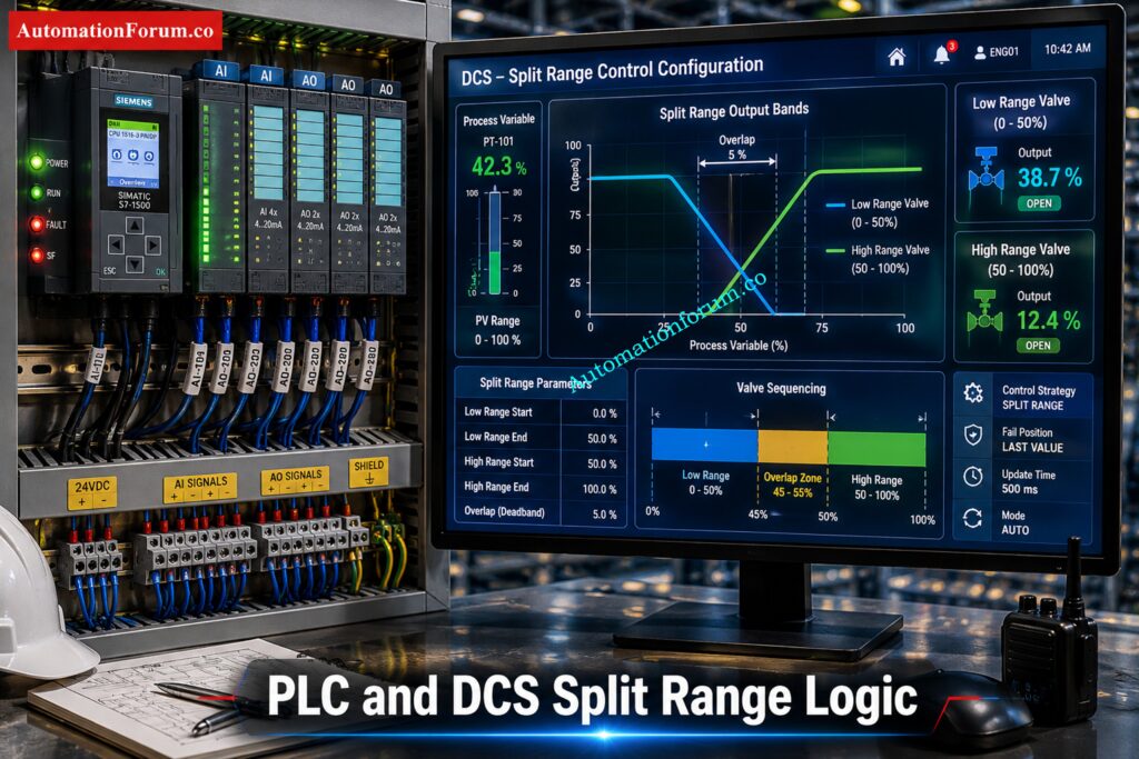
Split range control is a control strategy where one controller output is divided into multiple output regions to operate different valves or actuators.
Instead of sending the full output signal to one valve, the controller distributes the output across multiple valves according to predefined operating bands.
For example:
- Valve 1 may operate from 0 to 50 percent controller output
- Valve 2 may operate from 50 to 100 percent controller output
Importance of Split Range Control in PLC and DCS Systems
In some applications:
- The ranges overlap
- A dead zone or gap is intentionally created
This type of logic is very common in PLC and DCS based automation systems.
Refer the below link for the Understanding Complementary Split Range Control (CSRC)
Why Split Range Control Is Used in Process Industries
How Split Range Control Improves Process Stability
Split range control is used because many industrial processes cannot be controlled efficiently using only one valve.
Different valves may be required for:
- Low load operation
- High load operation
- Heating and cooling
- Fine and coarse control
- Makeup and venting
- Utility balancing
- Energy optimization
Why Multiple Control Valves Are Used with One Controller
Using multiple valves allows engineers to:
- Improve control precision
- Extend operating range
- Reduce valve wear
- Improve process stability
- Achieve smoother control transitions
Calculate Split Ranges Without Trial-and-Error Mistakes: Split Range Calculator – Control system
What Is a Split Range Calculator
Definition of a Split Range Calculator
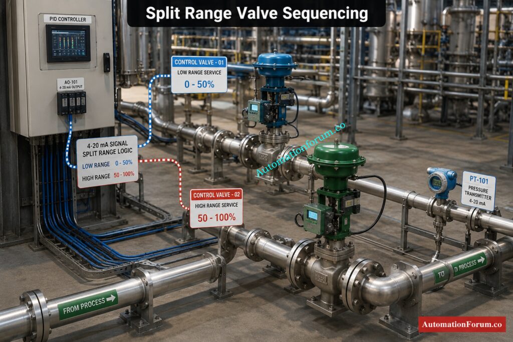
A Split Range Calculator is an engineering tool used to configure and analyze valve sequencing logic.
Purpose of a Split Range Valve Calculator
The attached calculator helps engineers determine:
- Which valve becomes active at a particular controller output
- Valve opening percentage
- Overlap regions
- Gap or dead band regions
- Valve sequencing behavior
- Direct acting and reverse acting response
- Output allocation between valves
How a Split Range Calculator Helps Automation Engineers
The calculator also helps engineers validate whether the sequencing logic is correct before implementation in a PLC or DCS system.
This is extremely valuable because many split range problems are discovered only during commissioning or startup.
The calculator reduces engineering errors and improves confidence before the actual process goes live.
Unlock Better Valve Sequencing in Real Plant Systems: Split Range Control in Control Valve Applications
Who Uses This Split Range Calculator
Instrumentation Engineers
Instrumentation engineers use this calculator during:
- Control valve design
- Loop configuration
- Valve sequencing review
- Commissioning
- Troubleshooting
They use it to validate valve bands, overlap settings, and output allocation.
PLC Programmers
PLC programmers use split range calculators while developing:
- Analog output scaling
- Valve sequencing logic
- Interlocks
- Output characterization
- PID control strategies
Ratio Control That Keeps Process Balance Rock Solid: What is Ratio Control in Process Industries and How it Works
DCS Engineers
DCS engineers use the calculator to configure:
- Split range controller blocks
- Valve characterization
- Output mapping
- Function block logic
- Sequence control
Commissioning Engineers
Commissioning teams use the calculator during:
- FAT
- SAT
- Startup testing
- Loop checks
- Stroke testing
- Performance verification
Process Control Engineers
Process engineers use split range calculations to improve:
- Process stability
- Energy efficiency
- Temperature control
- Pressure control
- Utility balancing
Industrial Maintenance Engineers
Maintenance teams use it during troubleshooting of:
- Valve hunting
- Oscillation
- Sticky valves
- Poor handover
- Dead zones
- Incorrect valve action
Master Valve Behavior Across Split-Range Control Modes: Understanding Control Valve Functions in Complementary, Exclusive and Progressive Split-Range Control Systems
When to Use a Split Range Calculator
This calculator is useful during multiple engineering stages.
During Control System Design
Used for:
- Determining valve split points
- Selecting overlap regions
- Defining valve action
- Designing PLC logic
- Preparing DCS configuration
Override Logic That Protects Plants from Bad Upsets: Override Control in Process Industries for Industrial Safety
During FAT and SAT Testing
Used for:
- Testing valve movement
- Verifying split points
- Checking valve handover
- Confirming overlap behavior
- Troubleshooting oscillation
During Troubleshooting of Control Loops
Used when:
- Process instability occurs
- Valve sequencing becomes abnormal
- PID loops become unstable
- Valve overlap creates issues
- Dead zones appear
Choose the Right Valve Sizing Numbers Every Time: Understanding Rangeability vs Turndown Ratio in Control Valve Sizing
Where Split Range Control Is Used
Split range control is used in many industries including:
- Oil and gas
- Chemical plants
- Refineries
- Power plants
- Food processing industries
- Pharmaceutical industries
- Water treatment plants
- HVAC systems
- Boiler systems
- Utility systems
Decode Cascade Diagrams Before Troubleshooting Gets Messy: How to Read a DCS Cascade Control Loop Diagram: A Complete Guide with Example
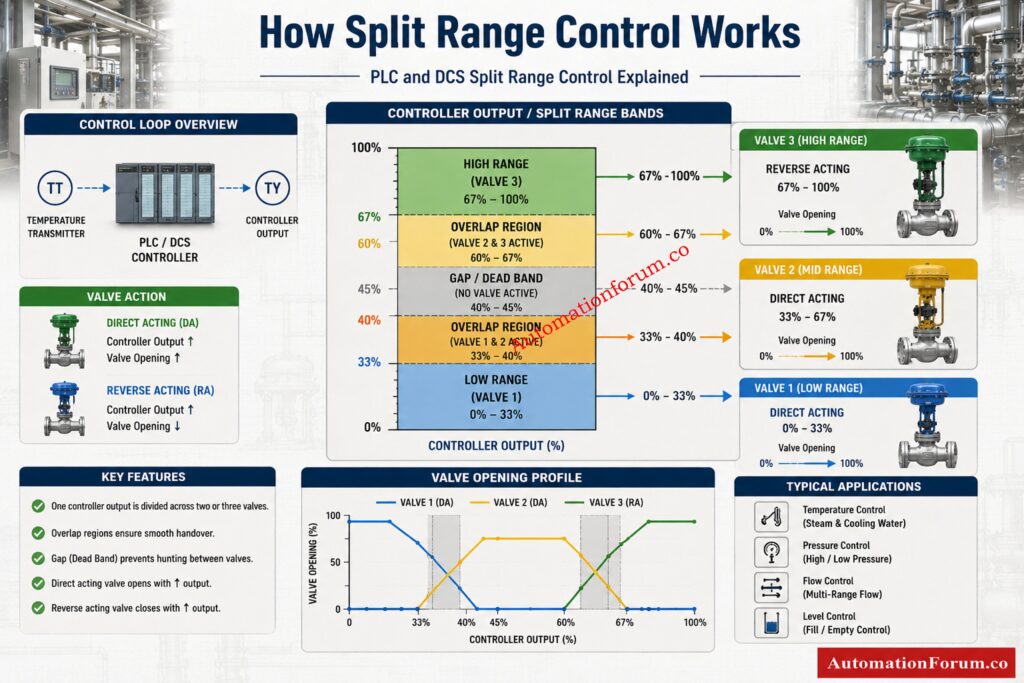
Working Principle of Split Range Control
Basic Philosophy of Split Range Valve Sequencing
The principle of operation is simple.
The controller output is separated in independent operating bands.
Each valve responds only within its assigned output range.
Understanding Controller Output Allocation
Example:
| Controller Output | Valve Action |
| 0 to 50 percent | Valve 1 active |
| 50 to 100 percent | Valve 2 active |
Understanding Valve Operating Regions
In overlap configurations:
| Controller Output | Valve Action |
| 45 to 55 percent | Both valves active |
In gap configurations:
| Controller Output | Valve Action |
| 48 to 52 percent | No valve active |
Must-Have Valve Hardware for Stable Process Performance: Essential Control Valve Accessories for Reliable Process Control
Understanding Direct Acting and Reverse Acting Valves
What Is a Direct Acting Valve
A direct acting valve opens as the controller output increases.
Example:
- 0 percent output = fully closed
- 100 percent output = fully open
What Is a Reverse Acting Valve
A reverse acting valve behaves in the opposite direction.
Example:
- 0 percent output = fully open
- 100 percent output = fully closed
The calculator supports both logic types, making it suitable for real industrial applications.
Tools Every Process Engineer Uses to Save Time: Essential Engineering Calculators for Process and Instrumentation Engineers
Understanding Overlap and Gap in Split Range Control
What Is Valve Overlap
Example:
- Valve 1 operates from 0 to 55 percent
- Valve 2 operates from 45 to 100 percent
Result:
- 45 to 55 percent becomes overlap region
Why Overlap Is Important in Valve Sequencing
Overlap helps:
- Improve handover smoothness
- Reduce process disturbance
- Avoid sudden control jumps
- Improve PID stability
What Is Dead Band or Gap Region
Gap means there is a region where no valve is active.
Example:
- Valve 1 stops at 45 percent
- Valve 2 starts at 55 percent
Result:
- 45 to 55 percent becomes dead zone
Problems Caused by Excessive Dead Band
Intentional dead band may be used to:
- Prevent both valves from operating together
- Reduce unnecessary valve movement
- Avoid interaction between utilities
However, excessive dead band can create instability.
PLC Signal Calculations That Cut Commissioning Errors: Collection of PLC Digital Signal Calculators for Industrial Automation
Features of the Uploaded Split Range Calculator
The attached calculator contains several advanced features designed specifically for automation engineers.
Two Valve Split Range Mode
Useful for:
- Heating and cooling systems
- Low and high capacity control
- Basic utility control
Three Valve Split Range Mode
Useful for:
- Advanced sequencing
- Multi stage utility systems
- Complex process control
Controller Output Configuration
Allows users to define:
- Output low limit
- Output high limit
- Current controller output
Valve Start and Stop Settings
Engineers can define:
- Valve activation start point
- Valve stop point
- Valve sequencing bands
Direct Acting and Reverse Acting Logic: Supports both valve action philosophies.
Live Controller Output Simulation
The slider allows engineers to test:
- Active valves
- Valve opening
- Sequence response
Valve Overlap Detection
Automatically identifies overlap regions between valves.
Gap Detection Feature
Identifies dead zones between operating ranges.
Validation Message System
Displays warnings for:
- Invalid ranges
- Excessive overlap
- Dead zones
- Incorrect settings
Valve Opening Percentage Calculation
Shows the actual opening percentage for each valve.
Sequence Mapping Visualization
Provides visual representation of:
- Valve regions
- Overlap areas
- Gap areas
Valve Status Display
Shows:
- Active valves
- Inactive valves
- Current operating condition
Full Range Sequence Table
Displays full operating behavior across the controller output range.
Formula Explanation Section
Helps engineers understand the engineering calculations behind the logic.
Excel Export Feature
Useful for:
- Engineering reports
- Documentation
- FAT reports
- Commissioning records
Replace a Bad Positioner Without Wasting a Shift: Faulty Control Valve Positioner Replacement Procedure with Checklist
Industrial Applications of Split Range Control
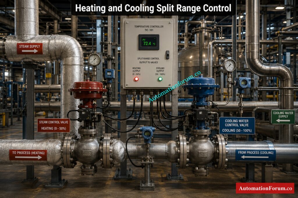
Steam and Cooling Water Temperature Control
One valve controls steam for heating.
Another valve controls cooling water.
The controller decides which utility should operate based on temperature demand.
Pressure Control Using Vent and Makeup Valves
Used with:
- Vent valves
- Makeup valves
- Relief systems
Allows smooth pressure balancing.
Boiler Fuel and Air Control Systems
Used in:
- Fuel sequencing
- Air control
- Load balancing
Reactor Heating and Cooling Utility Control
Allows smooth switching between:
- Heating utilities
- Cooling utilities
Fine and Coarse Flow Control Applications
A small valve handles precision control.
A larger valve handles bulk capacity.
Chemical Dosing Systems Applications
Used for:
- Low flow dosing
- High flow addition
- Accurate chemical control
Fuel Gas and Flare Systems Applications
Used for:
- Pressure balancing
- Safe venting
- Utility coordination
HVAC Automation Systems Applications
Used in:
- Chilled water systems
- Hot water systems
- Air handling systems
Big Instrumentation Calculator Collection for Daily Engineering Work: 100+ Online Instrumentation Calculators and Engineering Tools
Engineering Formula Explanation
Direct Acting Valve Opening Formula
Valve Opening = ((CO minus Start) divided by (Stop minus Start)) multiplied by 100
This formula determines how much the valve opens based on controller output.
Reverse Acting Valve Opening Formula
Reverse Valve Opening = ((Stop minus CO) divided by (Stop minus Start)) multiplied by 100
Used when valve response is reversed.
Overlap Calculation Formula
Overlap = Previous Stop minus Next Start
Positive value means overlap exists.
Gap Calculation Formula
Gap = Next Start minus Previous Stop
Positive value means dead zone exists.
APC Basics That Improve Plant Stability Fast: Advanced Process Control (APC): Working Principle, Components, Benefits, Applications and DCS Integration
Benefits of Using This Split Range Calculator
More accurate engineering calculations Reduced manual calculations.
Reduced Commissioning Errors – Assists in checking settings before to commencement.
Enhanced valve sequencing: Ensures a more seamless handover.
Improved PID Response. Improves loop stability.
Simplified PLC and DCS Configuration: Easier to Implement.
Easier Troubleshooting Identify:
- Wrong split points
- Overlap issues
- Dead zones
- Incorrect valve action
Improved Process Stability: Enhances overall control performance.
Three-Element Control Made Easy for Operators: Three Element Control
Real Engineering Challenges in Split Range Control
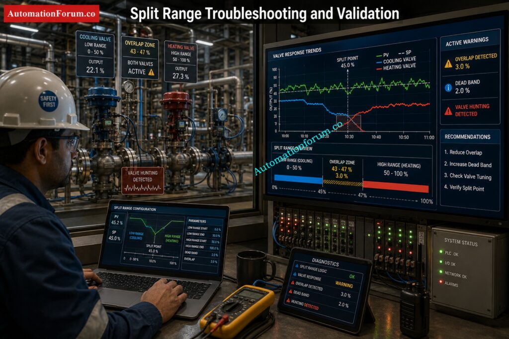
- Sticky Valves: Sticky valves lead to bad handover and unstable control.
- Valve Hunting: Happens when the overlap or tune is wrong.
- Bad Valve Handover : Split point drifting may induce sudden process disruptions.
- Unstable process response may be caused by excess dead band.
- Wrong Reverse Acting Configuration: Wrong action configuration causes wrong process behavior.
- Bad PID Tuning: Even solid split range logic might fail if tuning is bad.
Tune PID Loops for Faster, Cleaner Response: PID controller tuning
Best Practices for Split Range Control

Choose Correct Overlap Too much interaction overlap Little overlap means awkward handover.
Don’t Use Too Much Dead Band: Too much dead band makes it more difficult to run the system in a stable manner.
Always check for Valve Action during commissioning:
- Direct acting
- Reverse acting
Use Proper Valve Sizing Proper valve sizing is critical to split range performance.
Always test during commissioning:
- Valve movement
- Handover
- Overlap
- Gap behavior
Use Smart Positioners: Increases the accuracy and reactivity of the valve.
Tune PID Properly: Before tuning, check sequencing logic.
Follow Fail Safe Philosophy to make sure suitable fail action in:
- Air failure
- Signal failure
- Power loss
Find and Fix Offset Before It Hurts Production: What is offset in Process control?
FAQ Section on Split Range Calculator
What Is Split Range Control ?
Split range control is a control approach in which one controller output controls several control valves over different output ranges. It is frequently used in PLC and DCS systems for temperature, pressure and flow control applications.
What Is a Split Range Calculator?
A split range calculator is an engineering tool to compute valve sequencing, overlap, gap and controller output distribution among several valves. This lets engineers verify split range logic before commissioning and startup.
Why Is Overlap Used in Split Range Control?
Overlap is utilized for seamless transfer between valves and to prevent unexpected process interruptions during valve transition. It also enhances PID stability and minimizes oscillation around split points.
What Is Dead Band in Valve Sequencing?
Dead band is a region where no control valve is active between two operating ranges in a split range system. It is sometimes used intentionally to avoid simultaneous valve operation.
What Is a Reverse Acting Valve?
The reverse acting valve functions contrary to the controller output. That is, the valve shuts as the output increases or vice versa. It is utilized widely in split range heating and cooling applications.
Use Feedback and Feedforward to Control Faster: What are feedback and feedforward control?
How Does Split Range Work in PLC Systems?
Split range logic in PLC systems separates the controller output into different operating ranges for several valves/actuators. The PLC performs scaling and sequencing logic to open the appropriate valve within its programmed range.
How Does Split Range Work in DCS Systems?
DCS systems utilize split range control blocks or output characterization functions to divide one controller output to numerous control valves. This enables seamless sequencing and automatic valve handover.
What Causes Valve Hunting in Split Range Control?
Valve hunting is frequently caused by bad PID tuning, too much overlap, sticky valves or wrong split range setup. Oscillations can also be caused by improper valve sizing and inappropriate hand-over settings.
How Do You Calculate Valve Overlap?
Valve overlap is the difference between the following valve start point and the prior valve stop point. If the value is positive, both valves have an active operating region.
How Do You Tune Split Range PID Loops?
Split range PID loops are tuned by checking valve sequencing first, then tuning the proportional, integral and derivative parameters to provide a stable response. Proper selection of overlap and valve sizing is also vital for smooth control.
Where Is Split Range Control Commonly Used?
Common applications of split range control include chemical plants, refineries, HVAC systems, boilers, reactors, and pressure control. This is especially important when one controller has to operate more than one valve.
What Are the Advantages of Split Range Control?
Split range control enhances process stability increases operational range minimizes valve wear and enables smoother control transitions. It also provides better energy optimization and improved process efficiency.
How Do You Configure Split Range Valves?
Split range valves are designed by defining the distinct controller output ranges for each valve and defining direct or reverse action behavior . Then the overlap or dead band setting is changed according to the process need.
Why Is Valve Handover Important?
Valve handover is critical as faulty valve transitions can result in oscillation, instability and unexpected process upsets. Smooth handover enhances PID response and control performance.
What Is the Difference Between Overlap and Gap?
Overlap is when two valves are in common control of the output range of a controller, in overlap there is a dead zone where no valve is operating. Both conditions have a high impact on the process stability and control behaviour.
Alarm Management Rules That Reduce Plant Chaos: Guide to Industrial Process Alarms in Control Systems: Types, Classifications, and Management Methods
Conclusion: How This Split Range Calculator Helps Engineers
Split range control is one of the most practical and valuable control strategies used in industrial automation. It allows one controller output to efficiently manipulate many control valves throughout a range of operational circumstances.
When designed properly, split range control improves:
- Process stability
- Valve handover
- Energy efficiency
- PID loop response
- Operational reliability
The attached Split Range Calculator is a highly practical engineering tool for instrumentation engineers, PLC programmers, DCS engineers, process control specialists, commissioning teams, and maintenance engineers. It simplifies complex valve sequencing calculations and helps engineers visualize overlap, gap, direct acting behavior, reverse acting behavior, and valve allocation logic before actual implementation.
For real industrial automation projects, tools like this are not just useful. They are essential for achieving reliable, stable, and efficient process control systems.Refer the below link for the Understanding Complementary Split Range Control (CSRC)