- What is a controller and why is it required in a process system?
- What is a PID controller?
- What is the need for a PID controller in the process industry and how does it control a process?
- What is a reverse-acting controller?
- What is a direct-acting controller?
- What is the air to close valve?
- What is air to open valve?
- Direct-acting control Vs Reverse acting control?
- Different combination of PID control direction and Air to Close and Air to open valves?
- What is the importance of Air to close (FO) and Air to open valves (FC)?
- How to read Air to close (FO) and Air to open valves (FC) valves in a P&ID?
- What is the symbol of the Air to close (FO) valve?
- What is the symbol of Air to open valves (FC) valve?
Introduction
There are two basic actions of PID with respect to the control direction of MV. These are direct action and reverse action. Direct action will lead the MV to increase when the PV is larger than the SV.(For example, cooling application)· Reverse action will lead the MV to decrease when the PV is larger than the SV.(For example, heating application) A combination of all three of the actions described above is more commonly referred to as PID action. The waveforms of PID action are illustrated in Fig below. PID is the most often used corrective action for process control. There are however, many other types of control actions based upon PID action. Understanding the fundamentals of PID action gives a good foundation for understanding other types of controllers. The waveforms used have been idealized for ease of the explanation and are only an example of what may be encountered in practice. Loading is a function of demand and is not affected by the control functions or actions; the control function is to ensure that the variables are within their specified limits. To give an approximate indication of the use of PID controllers for different types of loops, the following are general rules that should be followed:
Pressure control requires proportional and integral; derivative is normally not required. Level control uses proportional and sometimes integral, derivative is not normally required. Flow control requires proportional and integral; derivative is not normally required. Temperature control uses proportional, integral, and derivative usually with integral set for a long time period. However, the above are general rules and each application has its own requirements.
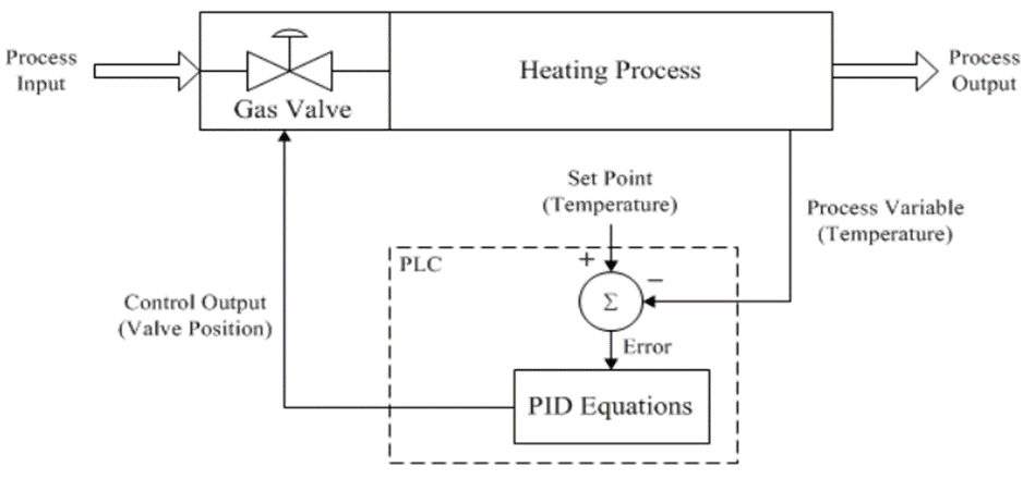
Normally the PID function is used to control process variables such as temperature, pressure, liquid level, or flow rate. The PID controller receives the process variable (PV) and controls the manipulation variable (MV) in order to adjust the PV to match the set value (SV). The figure below shows a typical configuration for a PID control system.
Process: A reaction which is controlled by physical values such as temperature, pressure, flow rate, etc.
Sensor: A detector that detects the controlled physical values. It can be a thermocouple, RTD, pressure gage, flow meter, etc.
Signal Converter: A device that transmits a weak sensor signal to the PID controller by converting it into the signal suited for the environment such as 4 – 20 mA, 1 – 5 Vdc, pulse train, etc.
Actuator: A device that regulates fluid or electric power to the process according to the signal generated by the PID controller. It can be a control valve, thyristor, variable speed drive, etc.
PV: Process variable … normally 4 – 20 mA or 1 – 5 Vdc analog signals
MV: Manipulation variable … normally 4 – 20 mA, 1 – 5 Vdc or a time-proportional pulse.
SV:Set value.
PID Equation: Controls the MV based on the magnitude of e and De and the PID tuning parameters. These parameters may be more or less aggressive based on system time responses and operator preferences.
What is a controller and why is it required in a process system?
The control system would check if there is any variation in the output from the required value. If the output has variation from the required value, then it would correct the output till the required value is received. The controllers in a process control system would act as a controlling element of a control loop. The controller would receive the error in some form and it would take proper action to rectify this error. The major purpose of a controller is to keep or maintain a process variable such as temperature, pressure, etc at the required value. So the controller would continuously monitor the error signal and it would give the required output to the final control element.
What is a PID controller?
The proportional integral derivative control is one of the major feedback-control which is used in the process industry. The PID controller is a continuous controller which means that the output of the controller would vary, smoothly according to the error or the rate of change of error. The controller would determine the error value by evaluating the difference between the setpoint and process variable. So after determining the error it would make a proper change in the process control input to remove the error.
What is the need for a PID controller in the process industry and how does it control a process?
So as we discussed earlier the PID control is a continuous control process and due to this it would monitor the output continuously and it would take necessary actions before the error. So we can carry out an industrial process without any error due to this PID feedback control. We can use a PID controller to regulate the flow, temperature, pressure, level, and many other industrial process variables.
The PID process control has three separate parameters such as the proportional, integral, and derivative.
Proportional control
In this mode of control, it would quickly respond to the current error, so the controller would act really fast
Integral control
In this mode of control, it would verify the previous errors, and it would respond to the accumulation of the errors in the form of average and thus it would provide a slow response which would drive the steady-state error towards zero.
Derivative control
In this mode of control, it would assume the future errors based on the previous errors. In this mode, it would take action according to the rate at which the error is varying. So in this type of control, it would provide an anticipatory response to the error.
What is a reverse-acting controller?
Reverse action controller
A reverse action controller can be described as, if there is a need for the increase in signal to the controller then the control output should be decreased. So a controller can be considered as in the reverse action operation when an increase in controlled variable against defined setpoint would cause a decrease in the controller output.
Example for Reverse acting controller
Reverse acting controller
The above image is an example for the reverse action controller, so if the outlet temperature increases above the set-point then the signal from the temperature transmitter increases. So in this case in order to keep the temperature to the setpoint, the controller would close the steam valve by a certain amount. To achieve this the controller would reduce its output signal to the valve. So, for the increase in signal to the controller requires a decrease in the controller output then the controller must be in reverse action.
What is a direct-acting controller?
Direct action controller
The direct-action controller can be described as there should be an increase in the controller output if we need an increase in signal to the controller. So a controller can be considered in direct action when there is an increasing value of the controlled variable that creates an increasing value of the controller output.
Example for the direct-acting controller
Direct-acting controller for level control
So when the level in the tank increases above the setpoint, then the signal from the level transmitter would increase. In order to return the level to the setpoint, the controller should open the outlet valve a little bit. The controller should increase its output signal to the valve. So in this case an increase in signal to the controller needs an increase in signal output then the controller can be considered as the direct-acting.
What is the air to close valve?
The air to close valve is a type of pneumatic control valve. This valve would fully open when there is an instrument air supply failure. This valve is also called a fail-open valve.
What is air to open valve?
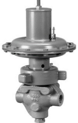
This valve would fully close when there is an instrument air supply failure, and it is also called a fail close valve.
Direct-acting control Vs Reverse acting control?
Controllers could be in the direct or reverse mode we can consider the direct and reverse as positive and negative. Mostly these terms are widely used in the case of control valves, positioners, and controllers. In a direct-acting controller, the output increases when the process variable is more than the set point and the output would decrease when the process variable is less than the set point. In the case of the reverse acting controller, the output decreases when the process variable is more than the set point and the output would increase when process variable is less than set point.
Direct-acting controller
The controller output would increase when the process variable increases and it would decrease when the process variable decreases. The sign(+,-) of the controller output will be the same as the sign of the process variable. In a direct-acting instrument, the output signal will increase when the input stimulus increases.
Reverse acting controller
In this type, the controller output would decrease when there is an increase in the process variable and it would increase if there is an increase in the process variable. The sign of the controller output will be opposite of the sign of the process variable. In the reverse acting instrument, the output signal decreases as the input stimulus increases.
Instances where the direct and reverse action is required
If the control valve and its controller are not in balance then the control valve would either go to the wide-open position and it would stay there, or it would stay close or act as though it is not responding. This situation can be handled by reversing the action of the controller.
Most control valves are used to do the pressure control, in this instance, the controllers would be reverse acting. Most of the pressure reducing valves would fail close and most back pressure control valves would fail open. If the pressure reducing valve were to fail open or the backpressure valve fail close then the controllers would have been direct-acting.
Different combination of PID control direction and Air to Close and Air to open valves?
Direct-acting controller, in fail to open valve
In this case, if the process variable is lower than the setpoint, the valve would open. If the process variable is more than the set point then the valve would close.
Direct-acting controller, in fail to close valve
In this case, if there is an increase in the process variable, then the controller output would be increased too and thus the valve would open. In case the process variable decreases beyond the set point then the valve would be closed an example of this would be back pressure control.
Reverse acting controller in fail to open valve
In this case when the process variable increase then the output of the controller would be reduced and this would open the valve. So when the process variable increases then the valve would be closed, an example of this would be the compressor recycle valve.
Reverse acting controller, in fail to close valve
If there is an increase in the process variable, then the controller output will be reduced and the valve would be closed. When the process variable is reduced beyond the setpoint then the valve would be open. We can use this for the pressure control application.
Some useful Questions
What is the importance of Air to close (FO) and Air to open valves (FC)?
Air to close valve
These valves would be normally open (fail open), so when the air pressure increases then the valve opening would get smaller. These valves are mostly used to prevent overpressure in case of a blocked line or in case of catastrophic, failure.
Air to open valve
These valves would be mostly closed, fail close, so when the pressure increases the valve’s opening would get bigger. So if the signal is lost then the valve will be closed. We can choose this valve in the case of a steam injection stream.
Importance of air to open and air to close valve
In case we need a valve to operate from high pressure to low pressure, then we can choose air to close valve, so that we can avoid the over-pressuring of the downstream facilities. The level control of the bulk separators will be an air to open valve. This valve is chosen to protect the surge tank from over-pressuring in case of a failure of the separator.
So we can use these valves to achieve the process safety, we can also ensure the fail-safe operation in case of emergencies such as power failure or in case if the airflow gets cut-off.
How to read Air to close (FO) and Air to open valves (FC) valves in a P&ID?
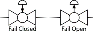
So in this image, we can see the P&ID symbol for fail to open and fail to close control valve. So If the actuator has a fail-safe position then it would be shown by an arrow between the valve and actuator and it would also be represented by letters such as FO & FC.
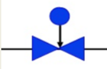
What is the symbol of the Air to close (FO) valve?
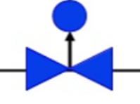
What is the symbol of Air to open valves (FC) valve?
Also, read
Continuous control mode- P, PD, PI & PID control modes