Table of Contents
Calibration principle:
- It is a straight line method with two points. At both ends, the transmitter extends the straight line beyond the calibration points.
- The High and Low calibration points may be anywhere between 0% (tank empty) and 100% of the total range (tank full).
- It is important that the low calibration point be established at a lower level than the high calibration point.
- For the best accuracy, two calibration points should be as far apart as possible.
- In order to calibrate the device, the output current has to be adjusted such that it corresponds to the actual level at two different calibration points.
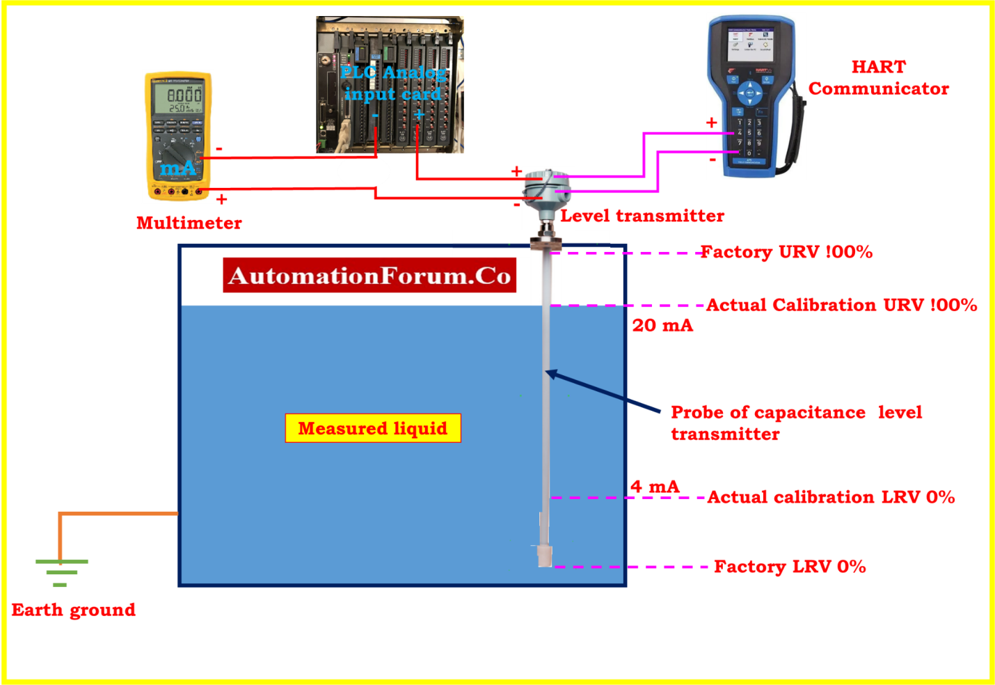
Calibration Setup
Safety
- Please refer to the link given below for information on calibrating operations in process industries, as well as information regarding fundamental safety and general guidelines.
Link: Basic Safety and General Consideration While Executing Calibration Process in process industries
- Put in a request with the panel operator to set the controller’s control loop to manual mode and the ESD loop to MOS mode.
- Connect the HART Communicator, and then use the data page to check a few settings. The tag number, PV, LRV, and URV are all common metrics.
- Isolate the instrument from the process as much as possible.
Method of calibration
Range selection:
- Prepare the tank by cleaning it and making sure that it is empty. Make sure that the temperature of the tank is within the specified operating range of the transmitter.
- Place the level transmitter on top of the tank. In order to measure the current, connect an ammeter in series with the supply.
- Choose the range. The range depends on the length of the probe and the dielectric constant of the liquid.
- To set an instrument’s range, you should always look in the manual for the device’s instruction.
- If it is a smart transmitter, you may configure its range using a Hart communicator or a hand-held communicator, which was advised by the manufacturers.
- Additionally, please refer to the instrument data sheet for commissioning parameter information.
- The range has been predefined by the manufacturer. It is not necessary to reset it until the probe length or liquid is changed in any way. So you may ignore this step.
- Examine the setup using the low range values of 0% and 4mA and the high range values of 100% and 20mA respectively.
- Check that the data you submitted is correct according to the datasheet that was available.
- Measurements for both LRV and URV are taken with the level transmitter probe at its lowest point.
Zero calibration:
- Fill the chamber of the level transmitter with water as a process fluid all the way up to the 0% level.
- Observe that the level is shown as 0% on both the display of the transmitter and the display of the HART communicator.
- Examine the reading on the level transmitter using a multimeter set to the mA scale.
- The zero calibration sets the level at which the transmitter will indicate a zero percentage output signal.
- To calibrate the zero percentage , the transmitter is set to its minimum level and the output signal is measured(4mA).
- If the output signal is not zero, the zero adjustment is made until the output signal reads zero(4mA).
- If necessary, use the HART communicator to modify the output of the transmitter on the multimeter to 4 mA.
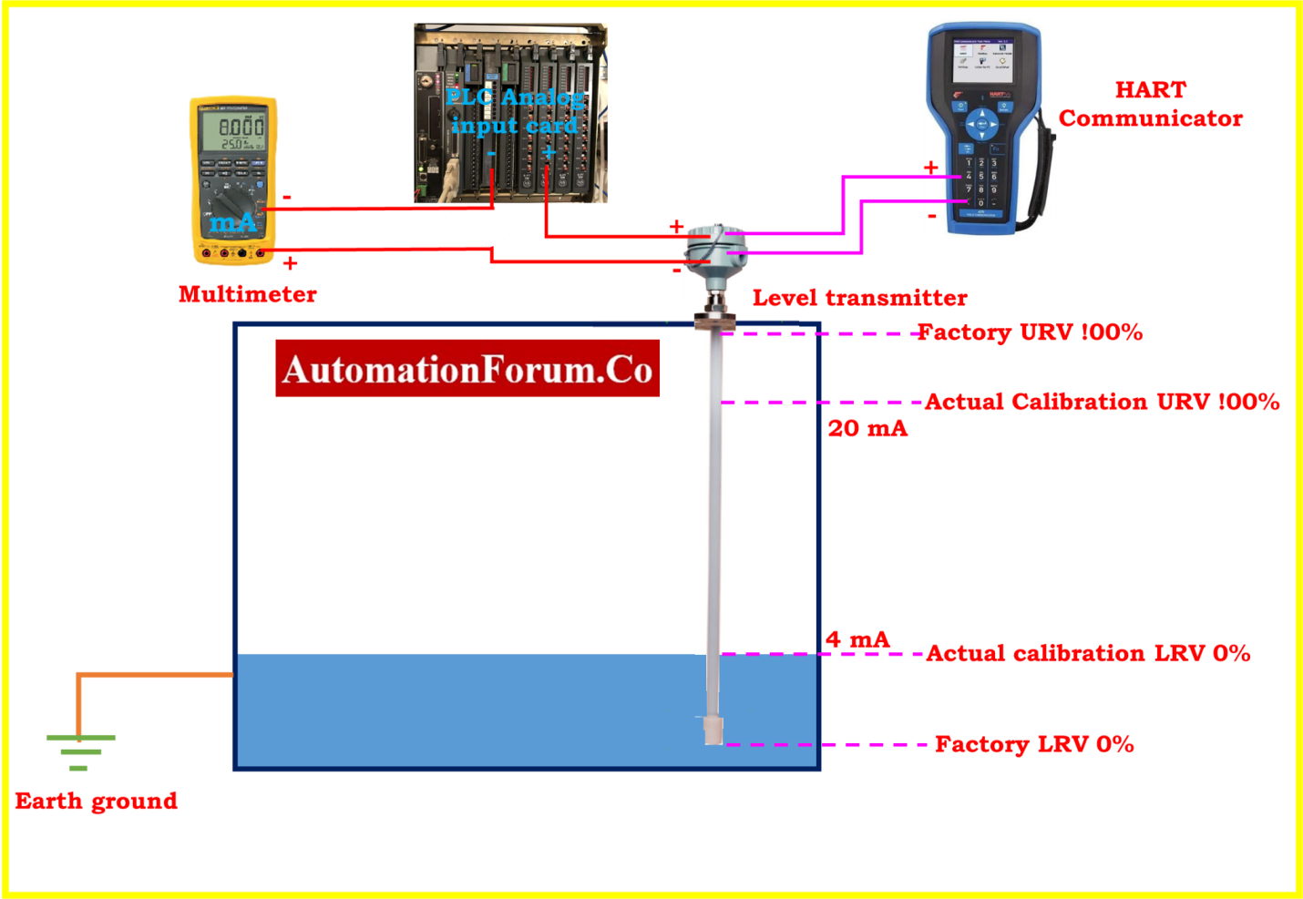
Span Calibration:

- To achieve a level of 100%, water should be fed into the chamber of the level transmitter.
- The level should be shown as 100% in both the transmitter display as well as the HART communicator display.
- Check the level transmitter using a multimeter set to the milliampere scale.
- In the event that it is necessary to do so, use the HART communicator to change the output of the transmitter on the multimeter such that the output must be 20 mA.
- If the output signal is not at the maximum, the span adjustment is made until the output signal reads the maximum of 20 mA.
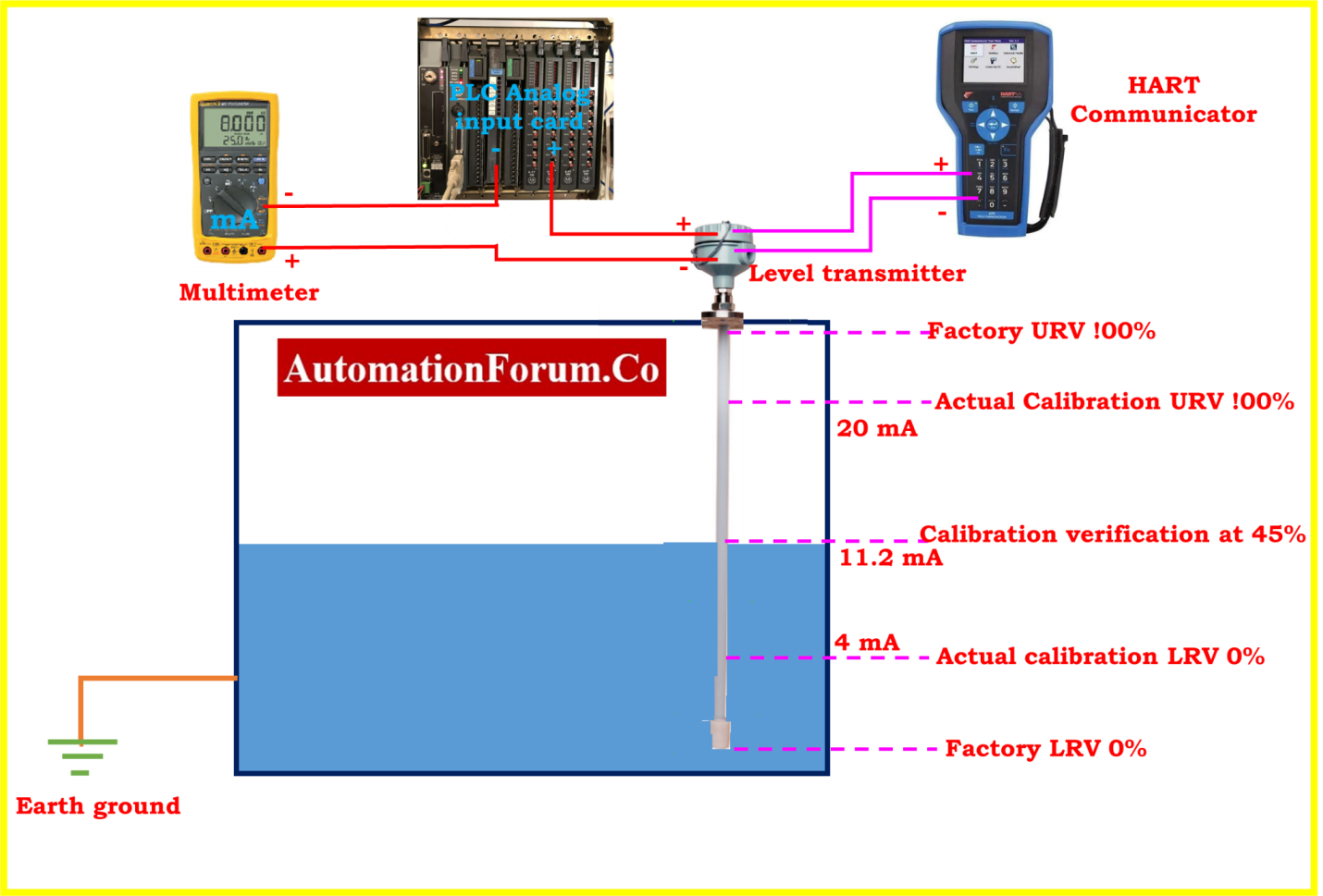
Calibration verification:
- After zero and span adjustments have been made, it is necessary to verify the calibration.
- This is done by measuring the output signal at several points between the minimum and maximum levels.
- The output signal should match the expected values for each point.
- For Example: It is recommended that the tank be filled up to between 0 and 100 percent of its maximum capacity. Use a dipstick to get an accurate reading of the level.
- Use the following calculation to get the predicted current from the output.
Expected current (mA) = ((Actual liquid level / Full scale level) * 16) + 4
- When doing the calibration verification on a vessel that was partially full, the following formula was employed to determine the level in milliamps:
EC = {(AL/FL) X16} +4
EC = Expected current signal in mA
AL = Actual Level is represented as a percentage.
FL = Full Level is represented as a percentage.
- Adjusting the unit’s calibration verification to 45% of the tank’s capacity:
EC = {(45/100) X 0.16} + 4 = 11.2 mA
- Calibration should be performed twice or three times on the transmitter to check its repeatability.
- Finally, the transmitter is tested with a known quantity of liquid in the tank to ensure that the measurement is accurate.It is important to follow the manufacturer’s instructions for calibrating the transmitter.
Recording calibration data
- Check the instrument’s calibration at 0% and 100% according to its range in both the upscale and downscale directions.
- Calibration needs to be done if the output value is not within a range that is acceptable. If all the output values are within acceptable ranges (+/-%), you don’t need to do any more calibration.
- Fill out the as found/as left column of the calibration report blank with the resulting output values.
- After the calibration has been completed successfully, the instrument should be labeled with the calibration.
Sample calibration report
The image that follows shows that the calibration for the capacitance type level transmitter sample report was done in the field.
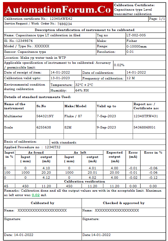
The Excel template used to create the calibration report for the capacitance type level transmitter may be obtained using the following link.