What is a loop diagram and how is it different from P&ID?

We could determine the process control system with the help of a loop diagram. The piping and instrumentation diagram does have many details but it doesn’t describe much about the field instruments which is used in the process control system. The loop diagram is composed of many of the field instrumentation such as field devices, measurement elements, wiring, junction box termination, and also other installation details. The loop diagram is also called a loop sheet and this diagram would have all the field devices in the process control system and all these field devices would be numbered. A loop diagram would indicate the field device installation details such as their wiring and also the junction box which would connect the field to the control system.
What are the major details that are included in an instrument loop diagram?
- Loop diagram would show the connection of the control system to the field devices
- It would show all the circuits, connection terminals, and their location
- This diagram would use graphical symbols for process display
- We can determine the instrument and junction box number
- We could get details such as the identification numbers of each terminal, conductor, cable, junction box, distributor, etc.
- Power supply circuit of the loop
- We can determine the terminal numbers which are assigned for the instrument
- The specified number of marshaling cabinets and also the terminal number of the marshaling cabinet can be easily determined
- This diagram would also show the details of the control system such as rack and I/O
- Electrical protections
- Signaling circuit indication
- Cable shield earth connection
How to read a loop diagram?
We must read a loop diagram from left to right from the starting to the end.
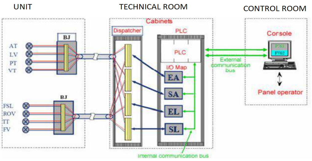
The unit
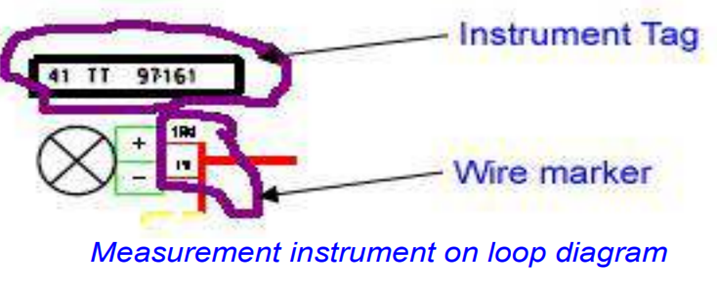
This section is composed of the measuring instrument, actuators, etc. All these devices would be connected to a junction box or a terminal board of the marshaling cabinet. A junction box would allow the collection of various signals on either side of the unit on a terminal board. This section would have measuring instruments and these instruments would be represented by instrument tags and wire markers.
Junction box
In this part, it would group measurements together at a point in an installation and this would avoid having one cable per sensor that runs towards the control room. In a loop diagram, the junction box would be represented by the terminal name, wire markers, and also terminal board numbers.

Marshalling cabinet (technical room)
In this section, we can see all the wires from the measurement instruments or from the junction box come together on a distribution terminal board. This distribution terminal board would lead all the measurement signals to many automation input/output boards. A ribbon data cable is used as a link between the distributor terminal and also automation input/output boards. In a loop diagram, the marshalling cabinet would be represented by the image terminal board and this terminal board would be composed of a unique number and also the cable marker.
System cabinet
The system cabinet has I/O cards, communication cards, and CPU cards. The marshaling cabinet would connect the field instruments to the system cabinet. In a loop diagram, the system cabinet would be represented with a board marker, a rack number, the slot number and also the number of channels used, and also the type of the board.

Control room
In this section, we can see the control station which communicates to the automation’s communication board via Ethernet link.
So with the help of these tag numbers, terminal numbers, and also the wire color we could determine the field instrument connection and it will be useful to determine the faulty sections and also to do the troubleshooting.
How to read tag numbers in a loop diagram?
Tag numbers will be given to the field instruments and each of them would have different tag numbers.
Tag number example – TIC 103
T 103 – loop identifier
103 – loop number
TIC – Function indication
The letters that make up the first few characters of the typical tag number are the leading letters, these letters are used to determine the function which is performed by the field device or by the control system. The loop number in the tag is used to determine if more than one field device is used to perform a specific function. So with the help of the loop number and the function letter we can easily determine the field device in a process area.
What is the purpose of the loop diagram?
- Loop diagrams are composed of wiring details of field instruments
- Engineering costs can be reduced
- Loop integrity is improved
- The faulty section can be easily determined with the help of a loop diagram
- Easy troubleshooting
- We could easily determine where the field devices are located and also their connection
- We can easily determine the control system installation by checking this diagram
- We could determine the termination numbers in the junction box
- The loop diagram shows how the field input and output are used in the control system