An electronic circuit is comprised of various electronic components, like resistors, capacitors, inductors, transistors, and diodes, connected by conductive wires and through the path an electric current can flow.
What is Open Circuit?
An open circuit is such an electric circuit that does not allow the electric current to pass through it. You may call it an open circuit if there is a break anywhere in the circuit, and so the current cannot flow.
In an open circuit, two terminals are detached from each other. As a result, the flow of electric current is discontinued. A voltage drop arises between the two terminals of the circuit even though the current cannot flow through the circuit. Hence, in an open circuit, the current flow is zero, but a non-zero voltage is present. We know that the power is equal to VI and the current flowing through an open circuit is zero. As a result, power is also zero, and so no power can be dissipated by an open circuit.

An open circuit is one in which the path has been broken or “opened” at some point, preventing current from flowing. For this reason, an open circuit can also be termed an incomplete circuit. An open circuit might be of two types; either it can be intentional or unintentional. The circuit to the room’s turned-off lights would be an intentionally opened circuit. Because the switch is in the “off” position, which “opens” the path via which power would ordinarily flow, there is no closed path available for energy to the lights. An example of an unintentionally open circuit is when a circuit breaker operates owing to too much electric current but switches it off.
Example:
Suppose the DC supply battery is connected in series with a bulb as load, resistance, and switch. When the switch is in open condition, the electric current does not flow from the battery (source) to the light (load).

Thus, this circuit does not conduct the electricity and zero potential difference occurs between two terminals of the open switch due to the incomplete path.
In another case, the same can happen if the insulators or insulating devices are connected in an electric circuit. Even though the circuit path is complete, electricity does not flow.
Given below is the diagram with the connected source, load, and insulator.

In this case, the current does not pass in a circuit, and light does not glow due to the presence of the insulator which means that, sometimes, an insulator behaves like an open circuit.
What causes an Open Circuit?
Component failure: Component failure occurs when one or more of the circuit’s components fails or is damaged. For example, suppose three resistors R1, R2, and R3 are connected in a circuit. R2 is burnt out due to a variety of factors. Here the open circuit is formed as the path is no longer complete.
Break-in Conductor: A conductor break can occur for a variety of reasons. Because of aging of wear and tear, conductors can break. The conductor may break by accident or for any other purpose. There are numerous causes for this, and all the reasons can be identified.
Manual Interruption: It can simply be done by turning off the light. A circuit breaker can be taken as an example. When a circuit breaker is opened manually for maintenance, an open circuit is actually generated.
- Open Circuit Resistance:
An open circuit signifies that the two terminals are externally detached, which is similar to the resistance of R = ?. This means that regardless of the value of the potential difference or voltage, no current can flow between the two terminals.
Ohm’s law describes the behavior of a resistor. According to this law, the current is proportional to the potential difference or voltage across the resistor. The Ohm’s law equation is:
V = IR
R = V/I
The current is zero I = 0 in an open circuit condition (If R = V/0, then R = ?). As a result, in open circuit conditions, for any value of voltage, the resistance is infinite.
Is Open Circuit dangerous?
Fuse is a term you are all familiar with. A fuse can also be used to produce an open circuit condition in unusual situations. As a result, a circuit or a specific piece of equipment is preserved. The fuse will be blown and the current will be cut whenever a high current passes through the circuit. In this case, the fuse is playing a role to create an open circuit. So, an open circuit is beneficial in certain instances, but not all.

Suppose we have an 11kV system. Power is transmitted via cables. The cable has been broken and the system is acting as an open circuit. Across the break, the full voltage is now available. If the voltage becomes too high, an arc is formed between the two breaks, so it can result in considerable power loss, and in severe cases, system destruction may also occur. This will not happen at low voltages. As a result, an open circuit is not always good, but sometimes can be dangerous.
What is a closed circuit?
When a circuit is complete and current can flow, the circuit is called a closed circuit. Electrical energy (electrons) is allowed to flow and move in the closed circuit and there are no interruptions in a closed circuit to stop the flow of power.
The current flows in a complete path when the switch is closed. The circuit is then ‘closed’ and functional. If the switch gets jammed in the ‘ON’ position, closed-circuit failure occurs.
Example:
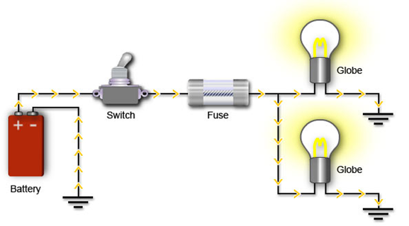
Let us consider a DC voltage supply battery is connected to the lamp (load) and the switch is closed. The electric current passes through the closed path in the circuit due to the closed switch. Hence the bulb is glowing in the closed circuit, as shown in the below diagram.

Difference between Open circuit and Closed-circuit
Here we will discuss some important comparisons between open and closed circuits:
| Characteristic | Open Circuit | Closed Circuit |
| Fundamentals | Does not create a sufficient channel for active energy to pass from the source to the load | Creates a complete path to flow the active energy from the source to the load |
| Current flow | Electric current cannot flow in an electrical open circuit | Current flows from the positive to negative in a closed circuit |
| Symbol | An open circuit is symbolized as ‘( )’ | The close circuit is represented as ‘(.)’ |
| Potential Difference | Does not exist between the two terminals of an open circuit | Exists between the two terminals of a close circuit |
| Nature | Across an open circuit, electricity cannot flow | A close circuit can transmit electricity by connecting the active elements |
Basic components involved in a circuit:
In any electronic system, electronic components are basic discrete devices to use in electronics or other fields. While building electronic circuits, you will have to work with a number of basic electronic components, such as resistors, inductors, capacitors, and integrated circuits. Below is a brief overview of some of the components and their functions.
Resistors: A resistor is an electronic device having two terminals that resist the flow of electrical current in electric circuits by providing resistance, thereby developing a drop in voltage across the device. It works based on the principle of ‘Ohm’s law’ which states that ‘voltage applied across the terminals of a resistor is directly proportional to the current flowing through it.
V = IR
Where R is the constant called resistance. The unit of resistance is the ohm.

Resistors are further classified into two types based on the power rating, types of material used, and resistance value. These resistors are used in various applications.
- Fixed Resistors: Fixed value resistors have a defined ohmic resistance and are not adjustable. These types of resistors are used most commonly. These resistors are used to set the right conditions in an electronic circuit.
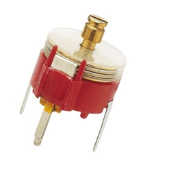
- Variable Resistors: A device that is used to change the resistance based on our requirements in an electronic circuit known as a variable resistor. These resistors are composed of a fixed resistor element and a slider that taps on the resistor element.
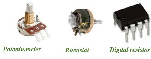
Potentiometer is a device in which a variable resistor is utilized as a potential divider using its 3 terminals. When two terminals are used and it functions as a variable resistor, is called a rheostat.
- Inductors: An inductor is a two-terminal passive electrical element. It stores electrical energy in the form of a magnetic field when electrical current flows through it. It is also known as chokes, coil, or reactor.
The alphabet ‘L’ is used to represent the inductor and it is measured in Henry. Inductors are typically available in the range from 1µH (10-6 H) to 20 H. The figure below represents the symbolic representation of the inductor.

An inductor is a coil of wire. It usually comprises of a coil of conducting material, typically insulated copper which is wrapped into an iron core which may either be of plastic or of ferromagnetic material. Hence it is called an iron-core inductor.
Inductance (L) is a property of an inductor that opposes any change in magnitude or direction of the current. The larger the value of inductance, the greater the capacity to store electrical energy.
The electric current flows through the coil and generates the magnetic field around it. The magnetic field generates the flux ? when the current flows through it. The ratio of the flux and the current gives the inductance.
L = ?/I
The inductance of the circuit usually depends on the path through which the current flows as well as the magnetic permeability of the surrounding material. Magnetic permeability is defined as the ability of the material to form a magnetic field.
Capacitor: The capacitor is an electronic element that has the ability or capacity to store energy in the form of an electrical charge which produces the potential difference across its plates. It is much like a rechargeable battery.
The capacitor is basically comprised of two or more parallel conductive plates which are disconnected from each other but are electrically separated either by air or by some good insulating material. Some form of liquid gel is used as an insulating material in an electrolytic capacitor. This insulating layer present between the capacitor plates is known as a dielectric.

Capacitance is measured in Farads which are very large units. So, micro-Farad (µF), nano-Farad (nF), and pico-Farad (pF) are generally used in practice.
The accumulation of charges in the conductors causes a potential difference across the capacitor plates. The charge accumulated in the capacitor is directly proportional to the voltage or potential difference developed across the capacitor:
Q ? V
Q = CV
C = Q/V
C is the proportionality constant, also called the capacitance of a capacitor.
The energy of a Capacitor: The energy is stored in joules and is equal to half of capacitances times the square of the capacitor’s voltage.
E = C X V2
The capacitor in Series: The total capacitance of the capacitors connected in series C1, C2, C3 ……..
1/CTotal = C1+ C2+ C3+…..

Capacitors in parallel: The total capacitance of the capacitors connected in parallel C1, C2, C3 ……..
CTotal = C1+ C2+ C3+…..

Types of capacitors:
- Film Capacitors: In this type of capacitor, plastic film is used as a dielectric medium. They are available in any value and voltages up to 1500 volts. They are ranging from 10% to 0.01% tolerance. There are generally two varieties of film condensers, radial type lead, and axial type lead.

- Ceramic Capacitors: This capacitor uses ceramic as the dielectric material. It is generally used in the circuits of high frequency such as audio to RF. By altering the thickness of the ceramic disc, ceramic capacitors can be used for high capacitance and low capacitance.

- Electrolytic Capacitors: In this capacitor, the oxide layer can be used as a dielectric material. Its tolerance capacity is wide. Their working voltages are up to 500V. There are mainly two types of electrolytic capacitors available, tantalum and aluminum.

- Variable Capacitor: In this type of capacitor, the air is used as a dielectric medium. The capacitance of a variable capacitor can be adjusted several times. This form of the capacitor can be used to set the resonance frequency of the LC circuits to change the radio so that its impedance matches the antenna tuner devices.
How to read resistance value?
The resistance value is a discrete value. The resistance value, wattage rating, and tolerance are usually mentioned on the body of the resistor when the resistor body is big enough to read the printed parameters clearly. But when the resistor is small, these specifications must be shown in some other way as the print is too small to read.
Small resistors use colored painted bands which indicate both their resistance value and their tolerance with the physical size of the resistor with their wattage rating. This is a widely accepted scheme developed long years ago as the simplest and quickest way to identify resistors’ ohmic value no matter what their size or condition.
Standard Resistor Colour Code Chart:

The Resistor Colour Code Table:-

Calculation of Resistor value:
In order to calculate the value of resistance, the following method is applied:
The left-hand or the most significant colored band is the band that is the nearest to a connecting lead with the color-coded bands being read from left-to-right as follows:
Digit, Digit, Multiplier = Colour, Colour x 10 colors in Ohm’s (?’s)
Example-1
Let us consider that we have a resistor with the following-colored markings:

Resistance = Yellow, Violet, Black, Red = 4,7,0,2 = 470×100 = 47000 ? or 47 K?
The fifth band denotes the percentage tolerance of the resistor.
Hence, Tolerance (Brown) -= ±1%
Tolerance of the resistor is an important parameter and is defined as a measure of the resistor’s variation from the specified value. If a 100 ? resistor has 10% tolerance, then its value can be any fixed value within 90 ? and 110 ?.
If the resistor has no fourth tolerance band, then the tolerance by default would be 20%.
Various logical circuit symbols:
There are varieties of different symbols for logical elements within a circuit. The most common circuit symbols are NAND, NOT, AND, and OR.
These circuit symbols are briefly described here.
- NOT Gate (inverter): This gate has only one input and the output is the inverse of the input. Hence the NOT gate is also known as an inverter.
| Input | Output |
| 0 | 1 |
| 1 | 0 |

AND Gate: An AND gate can have two or more inputs and its output is true only if all the inputs are true.
| Input | Input | output |
| A | B | X |
| 0 | 0 | 1 |
| 0 | 1 | 0 |
| 1 | 0 | 0 |
| 1 | 1 | 1 |

NAND Gate: This is an AND gate with the output inverted. A NAND gate may have one or more inputs and its output is true if NOT all the inputs are true.
| Input | Input | Output |
| A | B | Y = A.B |
| 0 | 0 | 1 |
| 0 | 1 | 1 |
| 1 | 0 | 1 |
| 1 | 1 | 0 |

OR gate: The OR gate may have two or more inputs and the output is true if at least one input is true.
| Input | Input | Output |
| A | B | X |
| 0 | 0 | 0 |
| 0 | 1 | 1 |
| 1 | 0 | 1 |
| 1 | 1 | 1 |

NOR gate: This is similar to an OR gate where the output is inverted. A NOR gate can have one or more inputs and its output is true if no inputs are true.
| Input | Input | output |
| A | B | Y |
| 0 | 0 | 1 |
| 0 | 1 | 0 |
| 1 | 0 | 0 |
| 1 | 1 | 0 |

EX-OR gate: This is like an OR gate and the output is true if both the inputs are different.
| Input | Input | Output |
| A | B | X |
| 0 | 0 | 0 |
| 0 | 1 | 1 |
| 1 | 0 | 1 |
| 1 | 1 | 0 |
