Introduction to Bently Nevada 3500 Series Troubleshooting Quiz
The Bently Nevada 3500 series vibration monitoring system is a set of machines that protects and predicts maintenance in process industries. When probes wander, proximitors fail, racks lose contact, or grounding causes noise, alarms can go off too early or not at all. To fix something, you need to know how sensors operate, how modules work, and how to install them. This quiz puts engineers and technicians to the test with real-life fault scenarios so they can improve their diagnostic skills, keep rotating assets safe, and make sure that critical plant operations are more reliable while also cutting down on downtime and expensive unplanned shutdowns during continuous production campaigns across compressor, turbine, pump, and gearbox trains for reliability.
Why Troubleshooting Bently Nevada 3500 Series is Critical in Process Industries
To keep machinery safe in process industries, it is important to fix problems with the Bently Nevada 3500 series vibration monitoring system. It makes sure that important equipment like turbines, compressors, and pumps are watched after correctly.
Machinery Protection: Finds problems early on and stops expensive equipment failures.
Avoiding False Trips: Stops false alarms caused by problems with the probe, grounding, or setup.
Predictive Maintenance: Makes ensuring that condition monitoring is done correctly so that faults can be found early.
Common Risks: These include problems with probes, proximitors, cables, power supplies, and communication.
Start the Advanced Vibration Monitoring Troubleshooting Quiz
In today’s automated factories, machine safety is no longer seen as a separate task from productivity. Engineers increasingly expect safety systems to keep workers safe while also making sure that production runs smoothly. The safety light curtain is one of the most used non-contact machine safety sensors. It makes an invisible wall with infrared beams and stops machines right away when that wall is broken.
For instrumentation and automation engineers, understanding how light curtain works in industry is important because these devices are often connected to safety relays, safety PLCs, emergency stop circuits, and industrial safety interlocks. When correctly selected and installed, a safety light curtain improves both protection and productivity. It allows operators to work closer to machines while maintaining a high level of risk reduction.
What is a Safety Light Curtain?
Safety Light Curtain Definition
A safety light curtain is a photoelectric safety device that generates a protected zone using multiple parallel infrared beams between a transmitter and a receiver. If any beam is blocked by a hand, finger, or body part, the system detects the interruption and shuts down the hazardous machine motion.
How a Light Curtain Safety System Protects Operators
Unlike a mechanical guard, which physically blocks access, a light curtain safety system explanation is based on detection. This makes it ideal for applications where frequent material loading, inspection, or maintenance access is needed. It is commonly used in presses, automated assembly machines, palletizers, packaging equipment, and robotic work cells.
A safety light curtain working principle is simple in concept but highly engineered in practice. It replaces physical guarding in many applications where frequent operator access is required, such as press machines, robotic cells, packaging lines, and conveyors. Instead of opening and closing a gate every time, the machine can continue operating with fast, controlled access protection.
Why Safety Light Curtains are Used in Industrial Automation
A light curtain is not a general-purpose sensor. It is a safety-rated device designed to operate with redundancy, self-monitoring, and fail-safe logic. That is why the output is usually based on OSSD output light curtain technology, where the outputs switch off when a fault or beam interruption occurs.
A safety light curtain consists of several critical parts, and each one has a defined role in maintaining safe operation.
Transmitter or Emitter
The transmitter sends multiple parallel infrared beams across the protected area. These beams are typically pulsed and synchronized so the receiver can distinguish them from ambient light. The emitter does not simply send one beam; it creates a grid of invisible detection paths.
Receiver
The receiver detects the infrared beams sent by the emitter. If all beams are received correctly, the system considers the safe state active. The receiver provides a stop signal through the safety output circuit if one or more beams are obstructed or if there is a problem.
Safety Relay or Safety PLC
The light curtain output may connect to a safety relay or a safety PLC, depending on how the system is set up. This device takes in the safety signal and tells the machine to stop or not move. In higher-risk systems, the safety PLC is preferred because it allows more advanced diagnostics and logic.
OSSD Outputs
OSSD stands for Output Signal Switching Device. These are safety-rated outputs that turn off in the event of a beam interruption, internal fault, or power loss. OSSD outputs help ensure that the system fails safe rather than failing in an unsafe way.
Safety Relay or Safety PLC
Industrial installations also include cables, connectors, status indicators, test signals, and diagnostic functions. These let maintenance workers easily find electrical problems, dirty lenses, misalignment, or mistakes inside a device.
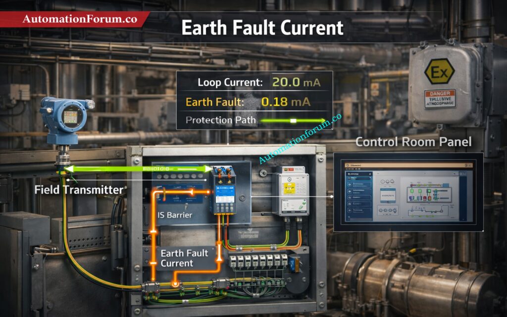
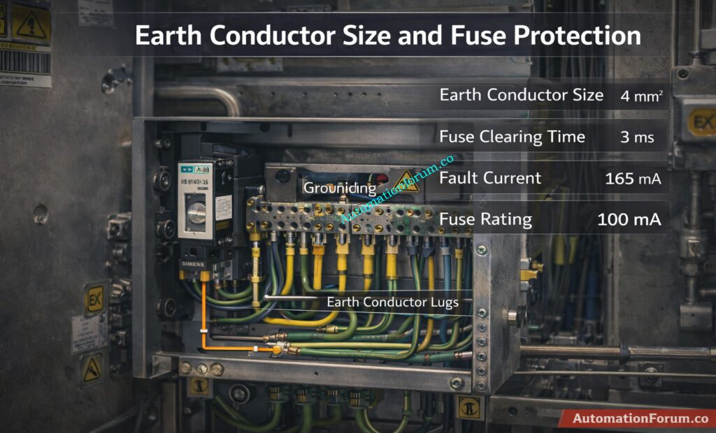
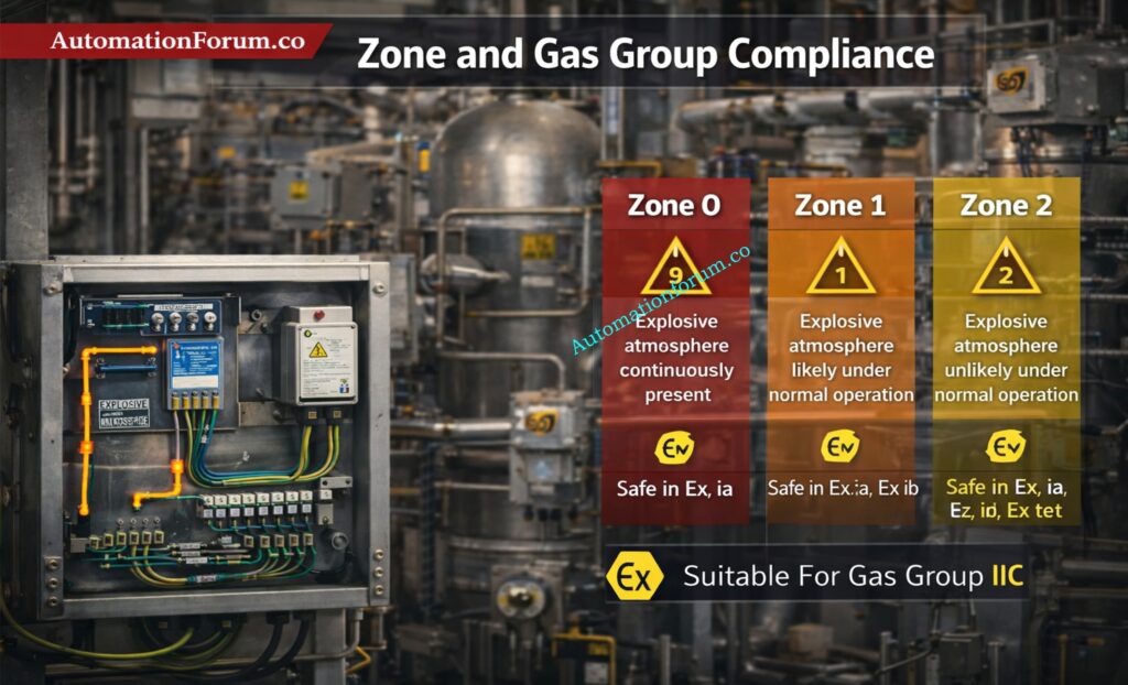
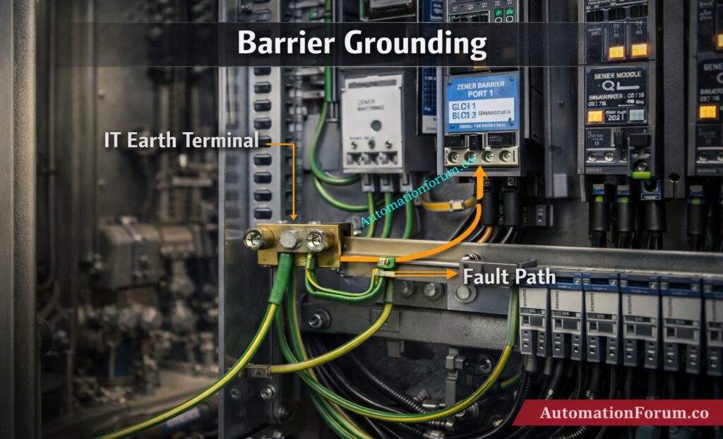
Refer the below link for the IS Barrier Earth Fault Current Calculator | Intrinsic Safety Loop Design Tool
The safety light curtain working principle can be understood in five basic steps.
Safety Light Curtain Working Principle Explained
The transmitter creates a series of parallel infrared beams across the sensing field. These beams form an invisible safety zone between the emitter and receiver. Depending on the application, the beam spacing may be very small for finger protection or wider for hand and body protection.
Infrared Beam Generation in a Light Curtain
The receiver continuously monitors the complete beam pattern. The beams are synchronized and modulated so that the receiver only accepts the correct signal from its paired transmitter. This prevents interference from sunlight, reflective surfaces, or other industrial light sources.
Beam Interruption and Hazard Detection
One or more beams are broken when an operator’s hand, arm, or body enters the protected area. The receiver immediately recognizes the beam loss as an unsafe condition. This is the key point in how light curtain works in industry: interruption equals hazard detection.
OSSD Output and Machine Shutdown
As soon as a beam is blocked, the OSSD outputs switch off. The connected safety relay or safety PLC receives the stop command and removes power or enables a safe stop function. The machine must stop before the operator can reach the dangerous motion zone.
Self-Monitoring and Fail-Safe Operation
A major advantage of modern safety light curtains is self-diagnostics. The device continuously checks for internal faults, output discrepancies, synchronization errors, and wiring problems. If a fault is detected, the system goes to a safe state. This fail-safe design is essential in industrial safety interlocks.
In simple terms, the system is always watching itself. If anything is wrong, the safest action is to stop the machine.
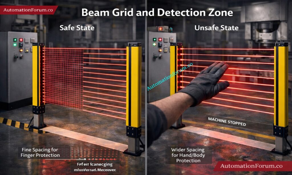
Think of the light curtain as a vertical curtain comprised of lines that you can’t see. The transmitter and receiver are on opposing sides of the opening, which makes a grid of beams across it.
The detecting zone is the safe area where any break in the beam is seen as a safety event. In a safe condition, all beams reach the receiver. In an unsafe condition, one or more beams are broken, and the safety output turns off.
This concept is important for engineers because the physical layout of the beam grid determines what size object can be detected. Fine beam spacing is used for finger protection, while larger spacing may be enough for hand or body protection.
A good installation makes sure the beam grid fully covers the hazardous access point without leaving gaps where an operator could reach through.
The most common classification is Type 2 vs Type 4 light curtains, based on IEC 61496.
Type 2 Safety Light Curtain
Type 2 devices provide basic safety functions and are generally used in lower-risk applications. They may be suitable when the risk assessment confirms that a lower safety category is acceptable. However, they offer less diagnostic coverage than Type 4.
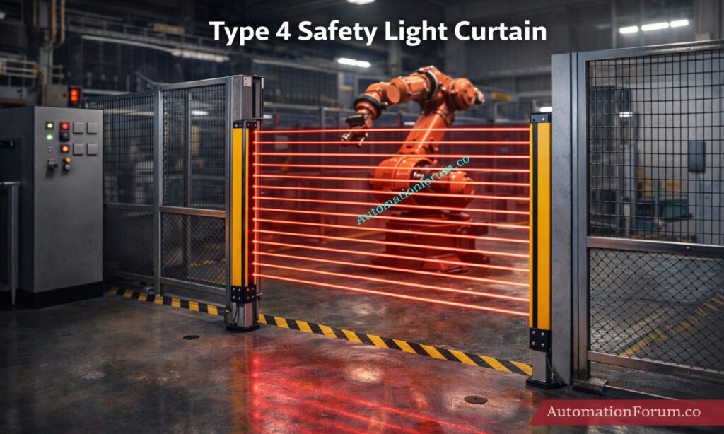
Type 4 Safety Light Curtain
Type 4 light curtains are the highest safety category commonly used in industrial automation. They provide greater fault detection, higher reliability, and are used in more demanding applications such as presses, robotic cells, and high-risk machinery.
Finger Protection, Hand Protection and Body Protection
The beam resolution determines what size object can be detected. A tighter beam spacing is used for finger protection, while wider spacing is used for hand or body protection. This selection must match the hazard and the required stopping performance.
Choosing the wrong resolution can create a false sense of safety or unnecessary nuisance trips.
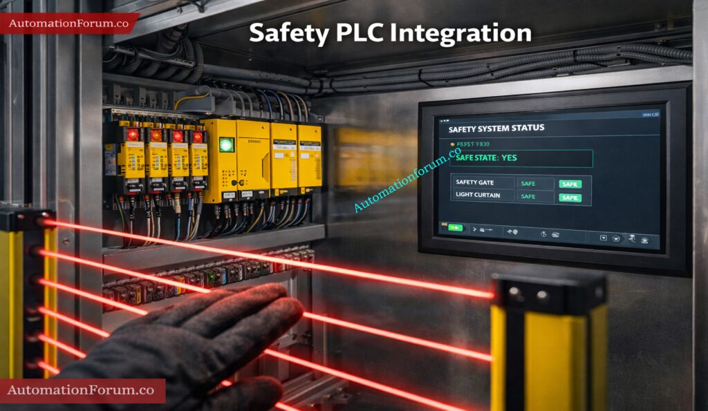
Safety Light Curtain Integration with PLC and Safety Systems
Safety light curtains are often integrated with a PLC, safety relay, or safety PLC. In standard industrial practice, the light curtain is not connected directly to the control logic that runs the machine sequence. Instead, it is connected to a dedicated safety circuit.
A simple logic example is:
Beam OK → Machine RUN
Beam Broken → Machine STOP
In real systems, this logic is implemented through safety-rated hardware and software, not ordinary PLC code alone. The safety circuit may control contactors, enable drives, or trigger a safe torque off function.
For complex machines, the light curtain may be integrated with emergency stop circuits, guard door switches, and muting logic. In a safety PLC environment, the system can also report diagnostics to the HMI or SCADA system without compromising safety integrity.
This is one reason why safety light curtain in PLC systems has become a standard topic for automation engineers. The control system must remain productive, but the safety function must always take priority.
This is the main standard for electro-sensitive protective equipment, including safety light curtains. It lays out safety classifications like Type 2 and Type 4, as well as functional requirements and test procedures.
ISO 13849 for Functional Safety
This standard talks about the safety portions of control systems and introduces Performance Level, or PL. Engineers generally figure out the PL that is needed by looking at the machine risk assessment.
IEC 61508 and Safety Integrity
This is the foundational standard for functional safety and introduces the concept of SIL, or Safety Integrity Level. While light curtains are usually specified through IEC 61496 and ISO 13849, SIL concepts are often used in broader safety system design.
OSHA Machine Guarding Requirements
In many workplaces, OSHA regulations also influence machine guarding and operator protection requirements. Even when local regulations differ, the principle remains the same: machinery must be guarded or protected by equivalent safety measures.
For engineers, it is important to understand that safety devices are not selected only by price or brand. They must be selected based on standards, risk level, stopping time, and application suitability.
Safety Light Curtain Installation and Design Considerations
A proper installation requires more than mounting the sensor and wiring it into a panel.
Minimum Safety Distance Calculation
The most critical design factor is minimum safety distance. The light curtain must be placed far enough from the hazard so that the machine stops before a person can reach the danger zone. This calculation must include response time, machine stopping time, and the possible approach speed of the operator.
Response Time of Safety Light Curtains
Every safety light curtain has a response time. Faster devices allow shorter safety distances, but the total system response must include the relay, PLC, contactors, and machine deceleration.
Installation Height and Beam Positioning
The mounting height should match the expected access point. A poorly positioned curtain may leave an unsafe gap at the top or bottom of the opening.
Environmental Factors Affecting Performance
Dust, oil mist, vibration, steam, and bright ambient light can affect performance. In harsh environments, the enclosure rating, alignment stability, and cleaning schedule become very important.
The main rule is simple: minimum distance must consider machine stopping time and human reach distance.
They do not require a physical barrier, so operators can access machines faster and more easily. That improves cycle time and reduces repetitive manual handling effort. They also reduce the need for opening and closing gates, which lowers operator fatigue and improves workflow.
In many applications, they provide a better balance between safety and productivity than traditional guards. They are also flexible to install because they can protect wide openings, access points, and transfer zones without major mechanical redesign.
Despite their advantages, light curtains are not perfect for every environment.
They may not perform well in areas with heavy dust, oil contamination, or vibration if the installation is poor. Misalignment between transmitter and receiver can cause frequent trips. Dirty lenses can block beams and trigger unwanted stoppages. Reflective surfaces near the sensing field may also create problems.
Another important limitation is that a light curtain is only one part of the safety design. It can’t take the place of a competent risk assessment, analysis of stop time, and machine control architecture. Engineers shouldn’t think that just one safety sensor makes the system safe.
Safety light curtains are popular in the process and manufacturing industries because they protect people without touching them and let operators work with machinery when they need to. They don’t block access like physical guards do, which makes them great for situations where you need to load, unload, or make changes often. Because they are so flexible, they are seen to be vital machine safety sensors in modern automation systems.
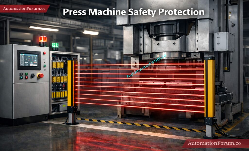
Safety Light Curtains in Press Machines
Safety light curtains are put in place at the front access point of press machines, where operators put in materials or take out produced pieces. These machines work with a lot of power and cycles that go very quickly, therefore it’s very important to protect the operator.
The light curtain keeps an eye on the opening all the time. If a hand goes into the danger zone, it stops the machine cycle or stops the press from stroking right away. This makes sure that the operator can’t get to the dangerous location while the machine is running, which greatly lowers the chance of getting hurt.
Safety Light Curtains in Robotic Cells
Light curtains are often used to protect the edges and access ports of robotic cells. Industrial robots move quickly and can be very dangerous if a person gets in their way.
The light curtain makes it safe to load and unload. The mechanism stops safely if someone crosses the protected zone while the robot is working. This makes sure that people and machines can interact safely without having to have full protection in all circumstances.
Packaging lines operate all the time, and operators often have to step in to clear jams, align products, or switch over to a new line. Light curtains are put up around conveyors, sealing equipment, and filling systems to keep people from getting in.
The light curtain picks up on the disruption when an operator reaches into the machine and safely stops the motion. This lets you act quickly while still getting work done, which is very important in fast-paced production settings.
Transfer points, infeed/outfeed areas, and accumulation sections are all dangerous areas in conveyor systems. These places are dangerous because they could trap or get stuck.
Safety light curtains keep an eye on these areas and halt the conveyor when the beam is broken. Compared to fixed guards, they provide easier access for maintenance and operation while still ensuring safety.
Safety Light Curtains in Material Handling Equipment
These applications clearly demonstrate how light curtains function as effective industrial safety interlocks. They lower the chance of accidents, make it easier for operators to go to work safely, and keep production going.
Safety light curtains are an important part of modern industrial automation because they combine quick reaction, non-contact sensing, and easy interaction with control systems.
If a light curtain malfunctions or trips a lot, it’s usually because of one of the following:
Misalignment between emitter and receiver
Dirty or scratched lenses
Loose wiring or damaged cables
Interference from reflective surfaces
OSSD output faults
Incorrect safety distance or mounting height
Before replacing the device, a disciplined maintenance crew should verify the alignment, cleaning condition, wiring integrity, and diagnostic signs. Installation problems, not product failure, are what generate a lot of false trips.
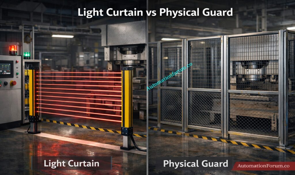
A physical guard is a solid barrier constructed of metal, mesh, polycarbonate, or similar hard material. The major thing it does is keep people from getting directly into the dangerous region. It’s simple, sturdy, and easy to grasp since it keeps the operator and the machine apart. It works well in situations where you don’t need to get to it while it’s running.
A safety light curtain, on the other hand, doesn’t physically obstruct entry. Instead, it uses infrared beams to make a safe area that you can’t see. The device will stop the machine right away if someone enters that area. This makes it better for equipment where workers have to load, unload, examine, or change materials often.
Feature
Light Curtain
Physical Guard
Access
Easy
Restricted
Safety
High
High
Productivity
High
Low
Maintenance
Medium
Low
Flexibility
High
Low
Access Control Comparison
A light curtain lets people in without having to open or move a barrier. This is useful when operators need frequent interaction with the machine. A physical guard restricts access more strongly, so the operator must usually stop the machine and remove or open the guard before entry.
Safety Performance Comparison
Both solutions can provide high safety when correctly designed. A physical guard prevents contact by blocking the hazard directly. A light curtain protects by sensing intrusion and stopping motion before contact occurs.
Light curtains usually support higher productivity because they reduce the time needed for access. When loading, unloading, or setting up, operators can get more done. Physical guards can slow down production since they have to be opened, closed, or taken off every time someone needs to get to something.
Maintenance Comparison
Because they are passive and don’t have electronics, physical guards normally need less upkeep. Light curtains need periodic checks for alignment, contamination, wiring issues, and correct operation of the safety circuit.
Flexibility Comparison
Light curtains are more versatile since they can protect open areas, transfer points, and access zones without completely closing them off. Physical guards are less adaptable, and if the layout of the process changes, they often need to be redesigned mechanically.
A physical guard is strong and easy to use, but it might slow things down. A light curtain is easier to use and more flexible, but it needs to be designed correctly, have the right safety distance, and be checked on a regular basis to stay safe.
Best Practices for Safety Light Curtain Installation
Before you install, always check the safety distance. Make sure the curtain resolution matches the real danger and need for access. Use a safety PLC or safety relay for critical applications rather than standard control logic. Test the system regularly and document inspection results. Never bypass or jumper the device during production.
For long-term reliability, train operators and maintenance staff to understand the light curtain function, so they do not treat it as a nuisance device. In reality, it is part of the core safety architecture of the machine.
Frequently Asked Questions About Safety Light Curtains
How does a safety light curtain detect objects?
It sends and receives signals using more than one infrared beam. The system knows that an object is blocking a beam and sends a stop signal.
What is OSSD in a light curtain?
OSSD stands for Output Signal Switching Device. It is a safety output that switches off when the curtain detects a fault or beam interruption.
Can light curtains replace safety guards?
In many applications, yes, but only after a proper risk assessment. They are not suitable for every hazard or environment.
What is safety distance calculation?
It is the minimum separation between the light curtain and the hazard so the machine can stop before the operator reaches danger.
Where are light curtains used in industry?
They are used in press machines, robotic cells, packaging systems, conveyors, and automated material handling equipment.
How does a safety light curtain operate?
A safety light curtain uses several infrared beams between a transmitter and a receiver to make an invisible wall of protection. If any beam is broken, the machine gets a stop signal right away to keep people from getting hurt.
What is a safety light curtain used for?
In industrial settings, a safety light curtain is utilized to keep people safe from dangerous machines. It keeps people out of harmful places by stopping machine operation and detecting entry.
What are the benefits of using a safety light curtain?
Safety light curtains improve operator safety while allowing easy and fast access to machines without physical barriers. They increase productivity, reduce downtime, and provide flexible installation in automation systems.
What is Type 4 safety light curtain?
A Type 4 safety light curtain is a high-quality safety equipment that can monitor itself and has backup systems. It is made for use in high-risk situations. It satisfies the greatest safety standards, such SIL 3, and gives you the most reliable protection.
What is the difference between Type 2 and Type 4 light curtains?
Type 2 light curtains are for lower-risk situations when basic safety features are needed. Type 4 light curtains, on the other hand, have more extensive diagnostics and can handle more faults. Type 4 is better for important machines that need more safety.
What is an alternative to a safety light curtain?
A physical guard, like safety fencing, gates, or mechanical obstacles, can be used instead of a safety light curtain. These safeguard by physically limiting access instead of using electronics to find intruders.
Conclusion: Why Safety Light Curtains Are Important in Modern Automation
One of the best ways to keep machines safe in modern automation is to employ a safety light curtain. It makes a protective field that can’t be seen, finds intrusions right away, and tells the system to halt safely through authorized safety outputs. The most important thing for instrumentation and automation engineers is to find a balance between safety and productivity.
A light curtain can be a reliable part of the entire risk reduction plan if it is chosen correctly, installed with the right safety distance, and connected to safety PLCs or relays. This is the kind of smart protection that keeps factories running securely, efficiently, and with less downtime in Industry 4.0 settings.
Refer the below link to Compare Zener and galvanic isolation: Understanding Zener vs Galvanic Isolation in IS Loops for 4 to 20 mA Systems
AUTOMATIONFORUM.CO·Your Trusted Source for Automation Power Tools & Solutions
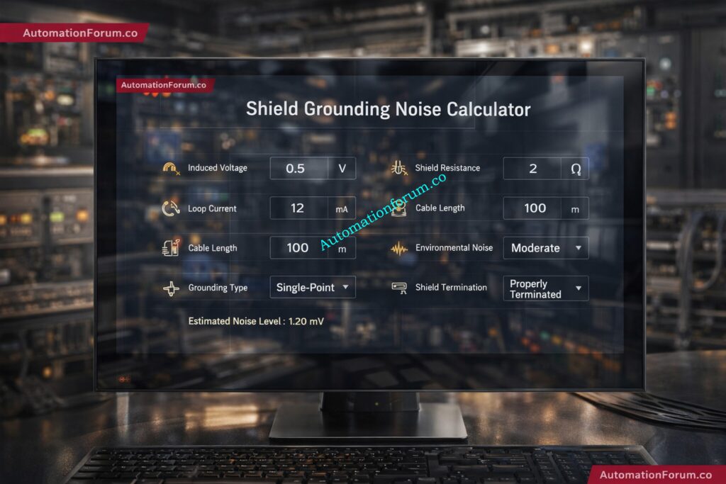
Shield Grounding Noise Calculator
Estimate shield-related noise and grounding impact for instrumentation cables
⚙ Input Parameters
📊 Results
Shield Resistance
—
Noise Level
—
Ground Loop Effect
—
System Status
—
Run the calculator to see your results
Fill in the parameters above and press Calculate.
📈 Live Graph — Noise vs Cable Length
Noise Level (V)
Ground Loop Effect (V)
📋 Parameters & Standards
Parameters Used
Induced noise voltage
Shield resistance
Ground loop current
Cable length
Environment noise factor
Grounding type
Shield termination method
Standards Referenced
IEC 60364-5-54
IEC 61000-4-1
IEC 61000-4-2
This is an engineering estimate for website use. Final design and installation should follow the applicable project specification, local electrical code, and EMC requirements.
💡 Engineering Guidance
Noise Voltage Impact: Higher induced voltage and longer cable runs increase estimated noise contribution in the signal loop.
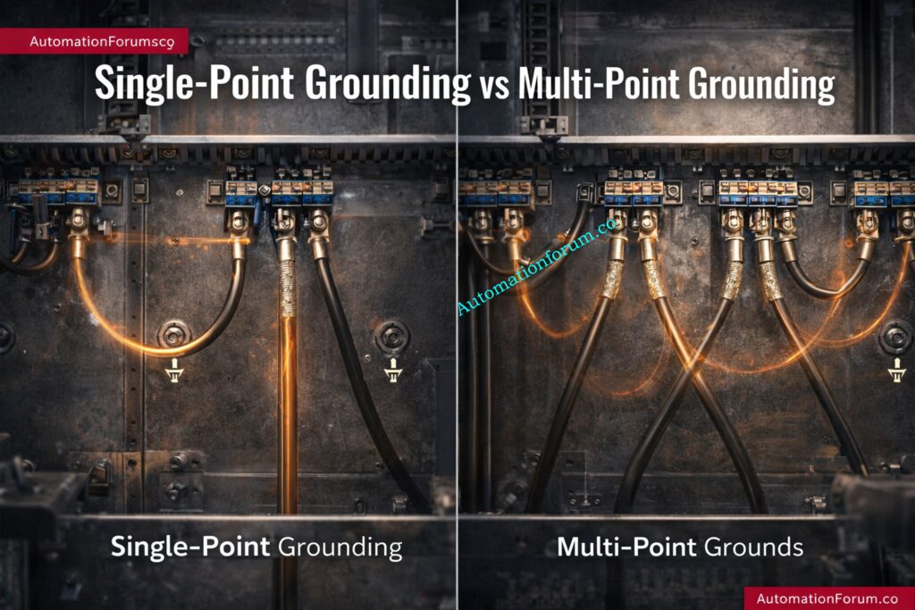
Ground Loop Effect: Multiple grounding paths can create circulating currents and measurement instability.
Single-Point Grounding: Preferred for most analog instrumentation — eliminates ground potential differences.
Cable Routing: Keep signal cables separated from power cables and VFD output cables.
Shielded Twisted Pair: Use STP for analog instrumentation loops to minimise differential noise pick-up.
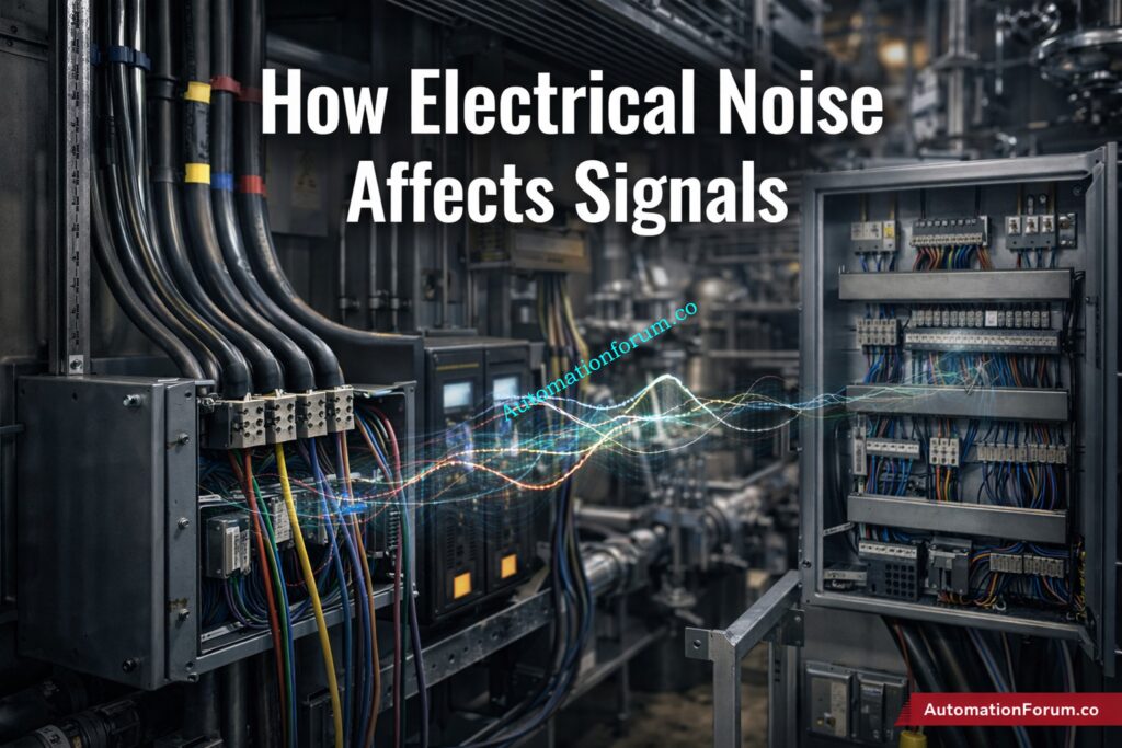
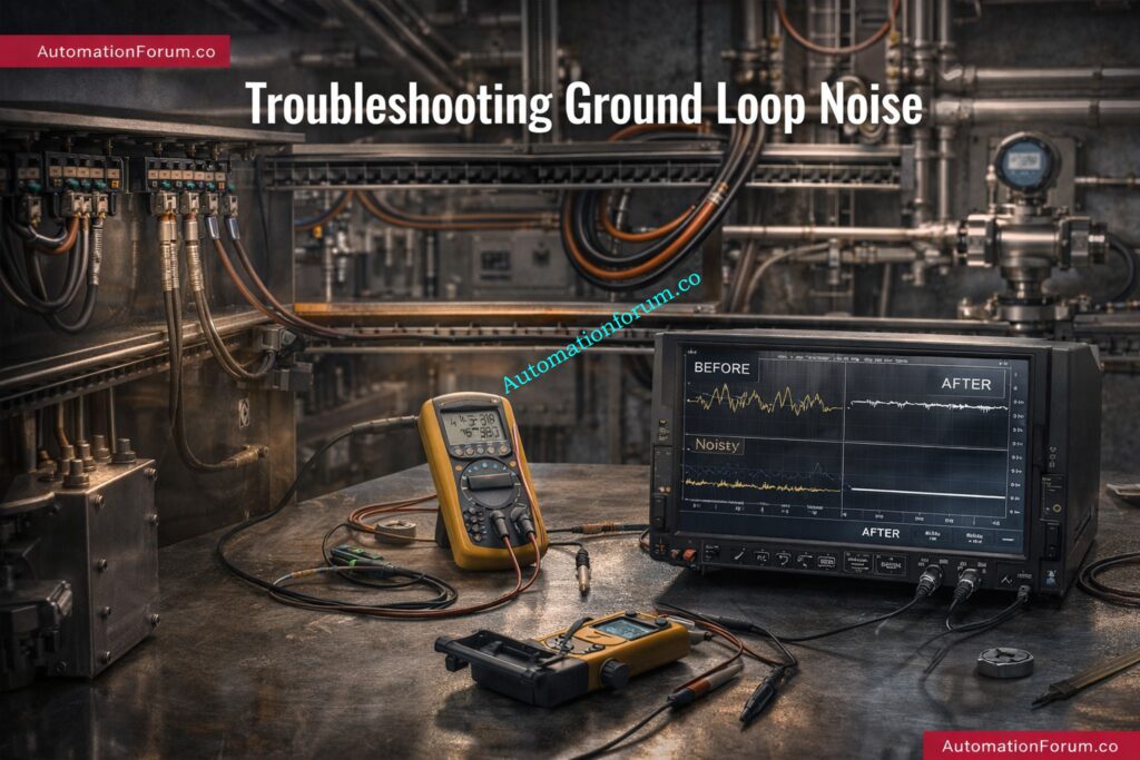
How Electrical Noise Affects 4-20 mA, Thermocouple and PLC/DCS Signals
In instrumentation and control systems, even a small amount of electrical noise can create serious problems. A noisy signal can cause a 4–20 mA loop to fluctuate, a thermocouple input to drift, or a PLC/DCS analog value to behave unpredictably. In real industrial plants, these issues often appear as unstable readings, false alarms, poor loop response, or repeated troubleshooting visits that never fully solve the root cause. That is why shield grounding in instrumentation is so important.
Why Shield Grounding Matters in Instrumentation and Control Systems
Proper cable shielding and grounding help protect low-level signals from EMI, RFI, and induced voltage from nearby power cables, motors, VFDs, and switching devices. But shielding is not simply about wrapping a cable in metal and connecting it anywhere to earth. Incorrect grounding can actually make the problem worse by creating ground loops, circulating currents, and additional noise paths.
Why a Shield Grounding Noise Calculator is Useful for Engineers
This is where a Shield Grounding Noise Calculator becomes useful. It helps engineers estimate the impact of induced voltage, shield resistance, loop current, cable length, and termination method on overall signal integrity. For commissioning,troubleshooting, or design review, this kind of calculation supports better decisions and more reliable instrumentation performance. As the source brief notes, electrical noise can distort low-power signals in instrumentation systems, which makes proper shielding and grounding essential.
Definition of Cable Shielding in Industrial Signal Wiring
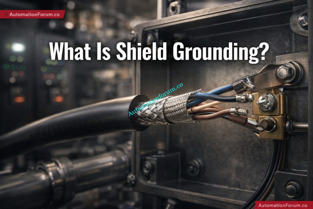
Shield grounding is the method of connecting the metallic shield of an instrument cable to earth or reference ground so that unwanted electromagnetic energy is diverted away from the signal conductors. The shield surrounds the core conductors and helps keep outside sources of interference from getting in.
Shielding is used in instrumentation systems to keep:
1. Capacitive coupling: If a cable is close to a conductor that carries power, electric fields can send undesired voltage into the signal cable.
2. Inductive coupling: When current in nearby cables changes rapidly, magnetic fields can induce voltage in adjacent conductors.
3. Ground loops: When shield or signal reference points are grounded at more than one location with different potentials, circulating current can flow through the shield or reference path.
Improper grounding can increase noise instead of reducing it, which is why shield termination must be planned carefully.
A simple grounding mistake can waste hours in troubleshooting, so a calculation-based approach helps engineers predict risk before the system goes live.
Parameters Used in the Shield Grounding Noise Calculator
A useful cable shielding noise calculation must evaluate several practical parameters. Each input reflects a real field condition.
Induced Noise Voltage
This is the voltage induced into the cable by external interference sources such as:
VFDs
Motors
Transformers
Switching contactors
Power cabling
A higher induced voltage means a stronger interference threat.
Shield Resistance
Shield resistance depends on the quality and construction of the shield material. A low-resistance shield provides better noise diversion and more effective protection.
Why it matters: If the shield has high resistance, interference current may not drain effectively to earth, allowing noise to reach the signal core.
Ground loop current is a major source of instability. It occurs when two ground points are at slightly different potentials, causing current to circulate through the shield or signal path.
Cable Length
Longer cables are more exposed to interference and have more opportunity to pick up induced noise.
General rule: The longer the run, the higher the likelihood of noise pickup, especially when the cable is routed near power systems.
Environment Noise Factor
Industrial environments are not equal. A clean control room is very different from a process area with:
large motors
VFD panels
welding equipment
heavy switching loads
A noise factor multiplier helps reflect this difference.
Grounding Type
The grounding scheme has a major impact on performance.
Practical Field Example of Shield Grounding Noise Troubleshooting
Problem Scenario in a 4–20 mA Pressure Transmitter Loop
A 4–20 mA pressure transmitter signal is fluctuating in a pump area. The transmitter is installed near a VFD panel, and the signal cable runs alongside power cables for several meters. The PLC input shows occasional jumps in pressure value.
Frequently Asked Questions About Shield Grounding Noise Calculation
Why is shield grounding important in instrumentation?
It protects low-level signals from EMI, RFI, and induced noise, helping maintain stable and accurate measurements.
Should the shield be grounded at one end or both ends?
For many analog instrumentation signals, one-end grounding is preferred to avoid ground loops. Both-end grounding may be used in some high-frequency cases.
What causes a ground loop?
A ground loop occurs when more than one ground path exists and current circulates due to different ground potentials.
How can I reduce cable noise?
Use shielded twisted-pair cables, improve grounding, avoid parallel routing with power cables, and reduce cable length where possible.
Why do long cables increase noise?
Longer cable runs have more exposure to EMI and greater opportunity for induced voltage pickup.
What are the common signs of poor shield grounding?
Signal fluctuation, unstable DCS values, drift, communication errors, and intermittent process readings.
When should I use multi-point grounding?
Multi-point grounding is more suitable for certain high-frequency applications, not for every instrumentation loop.
Can wrong shield grounding make noise worse?
Yes. Incorrect grounding can create additional loop currents and interference rather than reducing it.
Why Shield Grounding Should be Treated as a Critical Design Decision
Shield grounding is one of the most important details in instrumentation and control wiring, yet it is often ignored until noise problems appear in the field. A properly designed shield grounding noise calculator helps engineers evaluate cable shielding noise calculation, ground loop effect in control systems, and shield termination methods in a practical, engineering-focused way.
Final Takeaway for Instrumentation Engineers
For EPC design, commissioning,maintenance, and troubleshooting, this calculator supports better decisions and faster fault isolation. By considering cable length, induced voltage, shield resistance, grounding type, and termination method, engineers can reduce signal interference and improve system reliability.
In real plants, stable signals mean better control, fewer alarms, and less downtime. That is why shield grounding in instrumentation should always be treated as a critical part of the design, not an afterthought.
Refer the below link for Understanding Zener vs Galvanic Isolation in IS Loops for 4 to 20 mA Systems
Introduction to HMI Display Selection in Industrial Automation
A Human Machine Interface (HMI) is one of the most important operator-facing components in any industrial automation system. It acts as the bridge between people and machines, allowing engineers and operators to monitor process values, acknowledge alarms, change setpoints, and control equipment in real time. In modern plants, the HMI is not just a display; it is a decision-making tool that directly affects productivity, safety, and maintenance efficiency.
Importance of Choosing the Right HMI Display for Efficiency and Reliability
It’s very important to choose the proper HMI display because choosing the wrong one might make it hard to operate, cause communication problems, lower operator efficiency, and cause downtime that isn’t needed. It may be hard to read a panel that is too small, and an HMI with the wrong IP rating may break in moist or dusty places. Likewise, an incompatible communication protocol can create integration issues between the HMI and PLC.
Need for a Structured HMI Selection Guide for Industrial Automation
The goal isn’t only to acquire a screen; it’s also to find a solid interface that works with the application, the environment, and the long-term lifecycle needs. A thorough choice increases ROI, cuts down on the time it takes to fix problems, and makes the plant safer to run.
Role of HMI as a Human Machine Interface in Industrial Automation Systems
An HMI display provides a way for operators to see and manage industrial processes. It shows the status of machines, alerts, trends, recipes, and process parameters in a way that is easy to grasp on the plant floor.
The HMI is usually in the middle of the PLC, sensors, actuators, and the operator in an automation system. The PLC gathers field signals from sensors and runs logic on them. The HMI then turns that data into useful information for the operator. This means that the HMI is an important part of the automation architecture for communication and control.
Real-World Applications of HMI Displays
The HMI in a water treatment plant can show the levels of tanks, the status of pumps, and the amount of chlorine being added.
It may show the speeds of the motors, the state of the alarms, and the number of items produced on a packaging line.
In an oil and gas skid, it may present pressure, flow, temperature, and emergency shutdown status.
In HVAC systems, it may provide fan control, damper positions, and temperature scheduling.
For this reason, the right HMI display must match the application, process criticality, and operating environment.
Why Choosing the Right HMI Display Matters
The industrial HMI display selection criteria should always be based on practical plant requirements. A good HMI improves the way operators interact with the system, while a poor one creates friction and risk.
Key benefits of selecting the right HMI
Operator efficiency: Easy navigation reduces reaction time during abnormal situations.
Safety improvement: Clear alarms and simple controls support faster response.
Better safety: Clear alarms and easy-to-use controls let people respond faster.
Less human error: A logical interface cuts down on improper entries and missed warnings.
Faster fixing: Maintenance personnel can find problems faster.
Lower lifecycle cost: A reliable HMI cuts down on costs for replacement, downtime, and rework.
In short, the HMI with the most functionality is not always the ideal one for PLC systems. It is the one that works best for the job, the operator, and the plant.
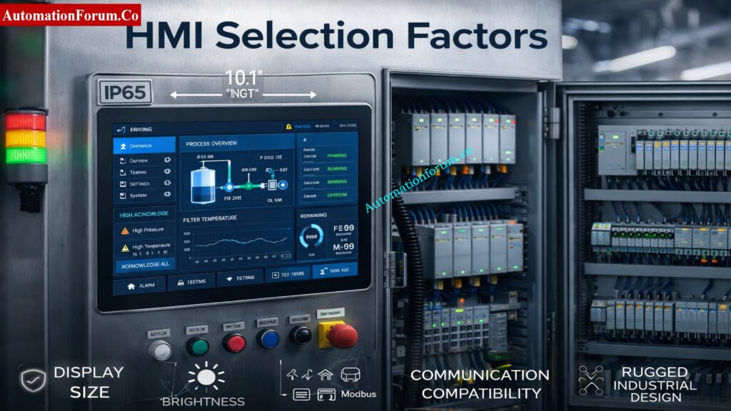
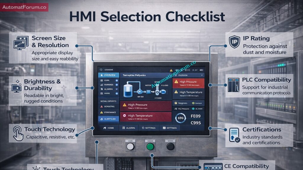
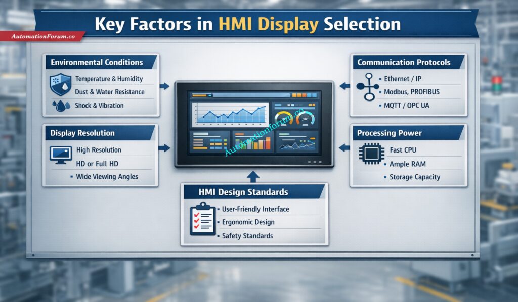
Key Factors to Consider When Choosing an HMI Display
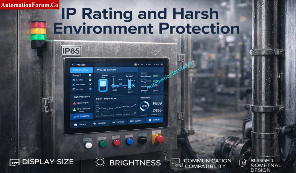
Environmental Conditions and IP Rating
The first step in any HMI panel selection checklist is evaluating the installation environment. An HMI used indoors in a clean electrical room has very different requirements from one installed on a dusty production line or outdoor machine.
Important factors to review
IP rating for HMI panel
Dust and moisture exposure
Temperature range
Vibration and shock resistance
Chemical exposure
Washdown requirements
Common protection levels include:
IP65: Protected against dust and low-pressure water jets
IP66: Stronger protection against powerful water jets
IP67: Protection against temporary immersion in water
NEMA ratings may also be relevant when selecting a panel for North American industrial applications. For outdoor or harsh environments, the enclosure and display protection must be chosen together. In hazardous areas, additional certifications may be required depending on the site classification.
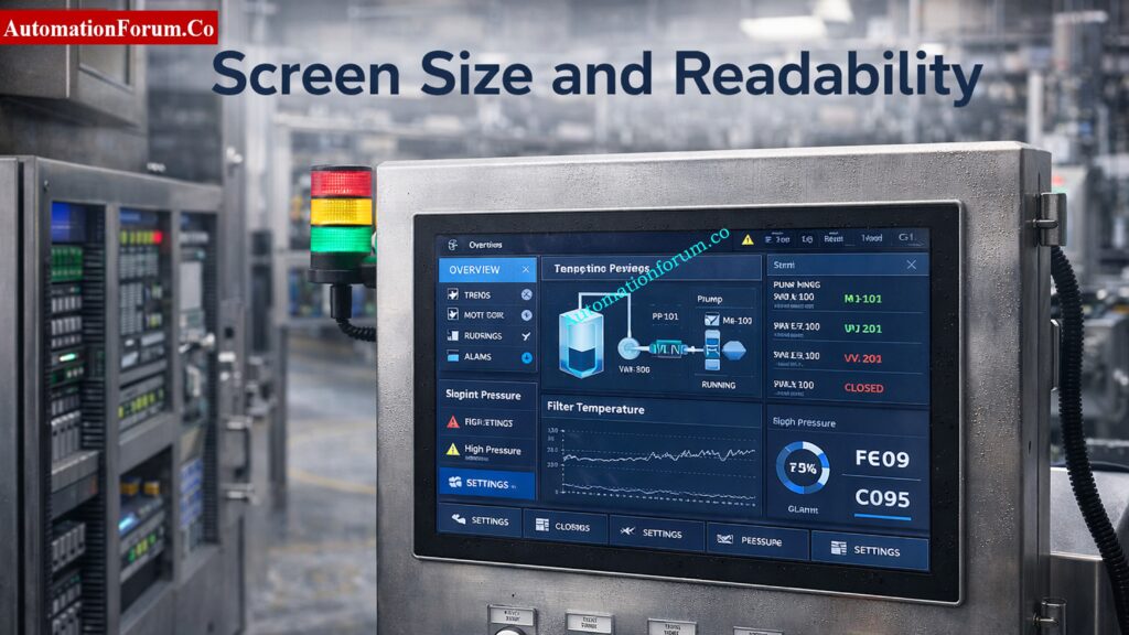
Display Size and Resolution
HMI screen size selection should be based on operator distance, amount of data displayed, and the complexity of the process. A small screen may work well for a simple machine, but a large process system often needs a bigger interface with better resolution.
Typical screen sizes
4-inch HMI: Compact machines, simple status display
7-inch HMI: General-purpose industrial machines
10-inch HMI: Moderate complexity with more tags and graphics
15-inch and above: Large systems, SCADA-like visualization, or control room use
What to consider
Viewing distance
Number of screens required
Alarm visibility
Trend display needs
Operator ergonomics
Higher resolution improves readability, especially when the screen includes detailed graphics, trends, or multiple values. For applications where operators must view the screen quickly from a distance, size and clarity matter just as much as software features.
When comparing touchscreen HMI vs non-touch HMI, touch technology is a major decision point. Even among touch panels, the type of touch interface matters.
Resistive touch
Works with gloved hands
Suitable for harsh industrial use
Can be used with stylus or finger
Usually less responsive than capacitive touch
Capacitive touch
Smooth and modern user experience
Better for multi-touch interaction
Higher clarity and sensitivity
May be difficult to use with heavy gloves
For many industrial applications, resistive touch is still preferred because operators often wear gloves and need reliable input in tough conditions. Capacitive displays are becoming more common in newer systems, especially where the environment is controlled.
Brightness is a major part of industrial display specifications HMI buyers should review. A display that looks fine in a design office may become unreadable on the plant floor if ambient light is too high.
A higher brightness rating improves readability in bright environments, but glare control is equally important. For outdoor cabinets, choose a display designed for sunlight readability, not only higher brightness.
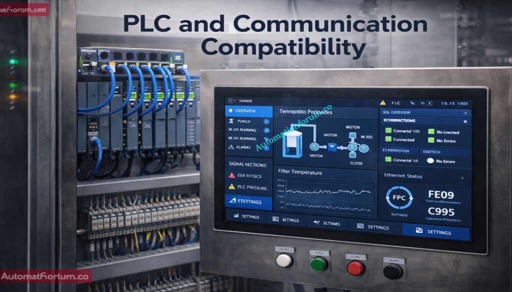
PLC, SCADA and Communication Protocol Compatibility
HMI compatibility with PLC/DCS systems is one of the most important selection factors. Even the best screen becomes useless if it cannot communicate properly with the controller.
Does it support the required communication protocol?
Can it handle multiple devices on one network?
Is driver support available for current firmware versions?
A reliable HMI selection guide for industrial automation should always include communication verification before final procurement. Vendor ecosystem compatibility is especially important when working with Siemens, Allen-Bradley, Schneider Electric, Mitsubishi, Delta, Omron, or other major platforms.
An HMI is more than just a screen; it’s a computer. The amount of memory and processing capacity it has affects how well it can handle alerts, data logging, trends, sophisticated visuals, and managing recipes.
If your memory is low or your performance is limited, your screen may take a long time to load, your computer may lag while it’s running, or it may not work at all. For modern automation systems, it is better to choose enough capacity for future expansion rather than only the minimum required today.
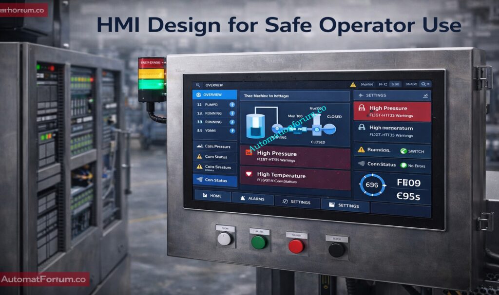
Good software design is just as important as hardware. The ISA 101 HMI design guidelines stress high-performance HMI principles that are based on clarity, uniformity, and operator effectiveness.
Good HMI design practices
Use simple navigation
Keep alarm screens visible and intuitive
Avoid cluttered graphics
Use consistent symbols and colors
Present only relevant process data
Support fast decision-making
A good HMI should enable operators immediately spot problems. Users shouldn’t be distracted by extra images or screens that are too full. This is very significant in procedures where the time it takes to respond is important.
Before finalizing the HMI selection, engineers should confirm mechanical fitment. The panel cutout, depth, cable routing, and mounting style all matter.
Check these items
Panel cutout dimensions
Back-panel clearance
Door thickness
Cable bend radius
Space for terminal connections
Retrofit compatibility
For retrofit projects, the new HMI should fit the existing enclosure as closely as possible. In modern panels, the layout can be more flexible, but access and serviceability are still important.
These are small and cheap, making them great for controlling small equipment and simple activities.
Advanced HMI Systems
These can handle more complex visuals, keep track of data, set off alerts, and occasionally even SCADA-like tasks.
Industrial PCs
Industrial PCs have more processing power and are more flexible, which is especially useful for applications that are complicated or use a lot of data.
Mobile or Tablet HMIs
Some current systems use them for portability and remote access, however they might not work in all industrial settings.
Each type should be selected based on process complexity, operator workflow, and maintenance strategy.
Refer the below link for the Factory Acceptance Test (FAT) Activities for SCADA System: Step-by-Step Checklist
How to Choose the Right HMI Display Based on Application
Different industries need different HMI features. Here are some practical examples.
HMI Selection for Manufacturing Lines
For production machines, speed, ease of use, and good interface with PLCs should come first. A 7-inch or 10-inch screen is often enough for local machine control.
HMI Selection for Oil and Gas Plants
For harsh and safety-critical environments, choose a rugged HMI with suitable IP rating, broad temperature tolerance, and reliable communication with control systems.
HMI Selection for Water Treatment Systems
In water treatment, the HMI should show levels, pumps, valves, alarms, and trends clearly. Data logging and remote access can be especially useful.
HMI Selection for HVAC Applications
For building automation, the HMI should be easy to use, energy-focused, and designed for clear visualization of temperatures, schedules, and equipment states.
HMI Selection for OEM Machines
OEMs usually need compact, cost-effective, and scalable HMI solutions that can be standardized across multiple machines.
Functional testing should confirm that alarms, trends, navigation, and communication work properly.
Plan for Scalability
Select a platform that can support future process changes or machine upgrades.
Consider Cybersecurity
Modern HMIs may connect to networks, remote access tools, or cloud platforms, so access control and data protection should be part of the specification.
Standardize HMI Platforms
Using common HMI platforms across multiple machines simplifies training, spares, and maintenance.
Choosing the right HMI display is a practical engineering decision that affects performance, safety, and lifecycle cost. The best selection is not based on screen size alone. It must consider environment, protection rating, brightness, resolution, touch technology, PLC compatibility, processing power, and software design. A organized method lets engineers choose a dependable interface that meets the plant’s real demands and avoid making expensive mistakes.
A good HMI selection guide for industrial automation should always start with the application, not the brochure. Engineers may make operator interfaces that are easier to use, safer to use, and more effective over time by using a clear HMI panel selection checklist, checking that the HMI works with PLC/DCS systems, and following ISA 101 design requirements.
The ideal HMI for automation projects is more than just a screen. It is a very important part of the control approach.
Refer the below link for the Proactive Maintenance Strategies for PLC I/O Modules: Reduce Downtime & Improve Reliability
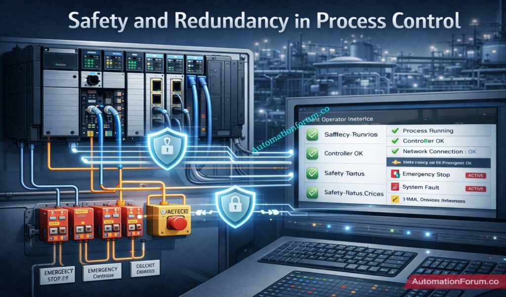
Traditional PLCs were built to execute deterministic control. Modern plants, however, need much more than basic logic: they need real-time motion, connected diagnostics, cybersecurity, safety integration, and data exchange with MES, SCADA, historians, and cloud layers. Rockwell Automation positions ControlLogix 5590 as a controller family designed for exactly this kind of connected, data-driven, performance-intensive environment.
How ControlLogix 5590 Fits Industry 4.0
That shift is what makes the term next generation PLC meaningful today. In Industry 4.0, the controller is no longer just a logic engine; it is also a data node, a security boundary, and a production-intelligence source. Rockwell’s documentation frames ControlLogix 5590 as a platform that brings together high-speed processing, integrated safety, and built-in security in a scalable architecture for modern industrial systems.
For engineering teams, that matters because many plants are now asking one control platform to handle motion, process, batch, safety, diagnostics, and connectivity without multiplying hardware and software silos. The ControlLogix 5590 family is presented as Rockwell’s answer to that requirement.
Standard, Safety, Redundant, and Logix SIS Variants
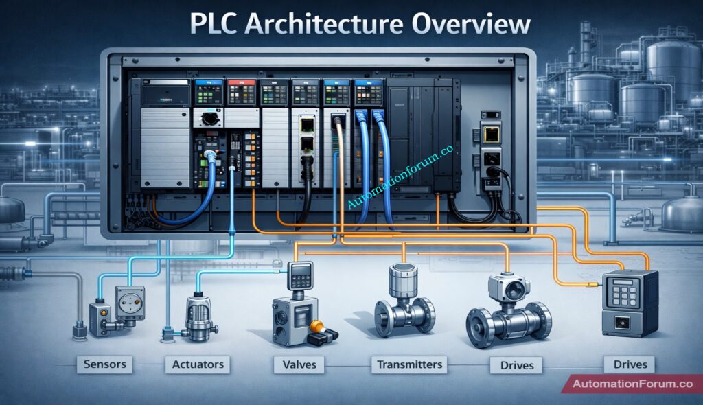
The ControlLogix 5590 PLC is the latest controller family in the Allen-Bradley Logix portfolio, designed for standard, safety, redundancy, and Logix SIS applications. It is a chassis-based controller that supports multiple communications and I/O options, and it is built to handle sequential, process, motion, and drive control within the same platform.
Where ControlLogix 5590 Is Used
Rockwell describes it as part of the broader Integrated Architecture offering, where the controller works with ControlLogix I/O modules, network communication modules, and the Studio 5000 environment. That modularity is important in real plants because it lets engineers build systems that scale from standalone machines to plant-wide automation architectures.
In practical terms, the 5590 is not a “single-purpose PLC.” It is positioned as a modern automation controller for high-performance manufacturing environments where safety, connectivity, and expansion are all part of the design brief. Rockwell also identifies variants for standard, XT (harsh/corrosive environments), and process use cases.
Rockwell states that ControlLogix 5590 offers expanded user memory, faster scan times, and high-performance control for demanding multidiscipline applications. The platform supports memory options from 2 MB up to 80 MB, which gives engineers room for larger programs, more tags, broader diagnostics, and more complex plant logic than smaller controllers.
This matters in plants where one controller may need to coordinate process loops, discrete sequencing, motion, and condition-based logic at the same time. Rockwell explicitly describes the 5590 as suitable for multidiscipline applications and a forward-engineered control system that supports more devices with secure data flow.
Advanced Motion Control and Scalability
The platform supports up to 512 real and virtual motion axes, which is a major step for packaging lines, robotics cells, handling systems, and synchronized manufacturing equipment. Rockwell positions this capability for robotics, packaging, and high-speed systems where a controller must keep up with coordinated movement across many servo-driven elements.
The important engineering point is not just the axis count. It is the scalability of motion inside the same control family. Instead of introducing a separate motion controller layer, ControlLogix 5590 lets teams consolidate high-speed motion with standard plant control, which simplifies troubleshooting, spare strategy, and lifecycle management. That is a practical advantage in large automation systems.
Refer the below link for Which PLC is Mostly used in the Automation Industry?
ControlLogix 5590 includes SIL 2 / PLd safety built into every controller variant. When paired with the 1756-L9SP safety partner, the controller can achieve SIL 3 / PLe capability. Rockwell also states that Logix SIS can achieve up to SIL 3 / PLe in redundant configurations, which is especially relevant for safety-critical process applications.
For engineers, this means safety does not have to be bolted on as a separate platform. The controller is designed so that standard and safety can coexist in one project and one engineering workflow. That unified approach reduces hardware complexity and can shorten validation time, especially when the process requires a mix of BPCS and SIS functions.
Industrial Cybersecurity and IEC 62443-4-2 Compliance
Cybersecurity is not an accessory in the 5590 family; it is built into the platform. Rockwell states that the controller is IEC 62443-4-2 compliant and includes CIP Security and secure boot. That combination is important because modern PLCs must defend not only against accidental changes, but also against unauthorized access and data-path manipulation across EtherNet/IP networks.
This is especially relevant for smart manufacturing PLC deployments where the controller is expected to exchange operational data with enterprise systems, remote support tools, and analytics layers. A controller that is security-aware from the start is easier to align with plant cybersecurity frameworks and defense-in-depth architectures.
Dual EtherNet/IP Connectivity and OPC UA Support
ControlLogix 5590 provides dual, 1 Gb embedded EtherNet/IP ports and can be configured for dual IP addresses or DLR. Rockwell also states that the platform handles 600+ Ethernet nodes per controller, giving it the network scale needed for large plants with broad device counts.
OPC UA support is another major feature. Rockwell’s product information shows the 5590 is positioned for modern communication and secure data flow, while the product release notes describe support for modern protocols such as OPC UA to enable vendor-neutral data exchange between OT and IT systems. That makes the 5590 a better fit for IIoT and analytics-heavy architectures than older, more isolated PLC generations.
The 5590 is a chassis-based modular architecture, which means the controller works together with I/O modules and network modules rather than as a fixed, monolithic device. Rockwell’s system guide says the ControlLogix 5590 system consists of the controller, the Studio 5000 environment, ControlLogix I/O modules, and network communication modules.
Support for Standard, Safety, Redundancy and SIS Architectures
That modularity is valuable because it lets engineers tailor the system to the application. A process plant may need a different combination of communications, safety, and I/O than a packaging line or a robotics cell. The 5590 family also supports standard, safety, redundancy, and Logix SIS architectures, so the same controller platform can fit multiple design philosophies.
Embedded EtherNet/IP Ports and Network Topologies
On the networking side, the controller’s embedded EtherNet/IP ports support linear and DLR topologies. In practical plant terms, that reduces the need for extra network modules in many designs and helps simplify the cabinet layout. Rockwell also indicates that the front Ethernet ports can be configured for DLR or dual-IP operation, which gives engineers more flexibility in segmentation and network resilience.
For high-availability applications, Rockwell provides dedicated redundancy documentation and reference architectures. The 5590 technical resources include standard architecture, security architecture, redundancy architecture, Logix SIS architecture, and safety architecture, which shows that the family is designed to support different plant risk profiles and availability targets.
ControlLogix 5590 vs Previous Generations (5570 / 5580)
The clearest way to understand the value of the 5590 is to compare it with the 5580 family. Rockwell’s 5580 documentation shows a platform with an embedded 1 Gb Ethernet port, up to 256 axes, and enhanced security features; the 5590 moves beyond that with dual 1 Gb embedded Ethernet ports, up to 512 axes, 600+ Ethernet nodes, and up to 80 MB memory.
ControlLogix 5590 vs ControlLogix 5580
Area
ControlLogix 5590
ControlLogix 5580
Engineering takeaway
Memory
Up to 80 MB.
3 MB, 5 MB, or 10 MB depending on model.
5590 is better for larger programs, richer diagnostics, and more complex multidiscipline control.
Motion
Up to 512 real and virtual axes.
Up to 256 axes.
5590 is more suitable for large motion and robotics systems.
Ethernet architecture
Dual embedded 1 Gb ports, DLR or dual-IP.
One embedded 1 Gb port, with chassis communication options.
5590 simplifies network design and improves resilience.
Node scale
600+ Ethernet nodes per controller.
5580 network capacity is lower, with the technical data showing 528 EtherNet/IP and 512 TCP for certain modules.
5590 is better for larger connected plants.
Safety/security
SIL 2/PLd in every variant, SIL 3/PLe with safety partner, IEC 62443-4-2, CIP Security, secure boot.
5580 also supports strong safety and security, but with lower capacity and older architecture.
5590 is a stronger fit when safety and cybersecurity must scale together.
Why the 5590 Is a Major Upgrade
The practical migration message is simple: the 5590 is not just an incremental refresh. It is a capacity and connectivity jump that targets plants needing more axes, more nodes, stronger security, and a more unified engineering model.
Refer the the below link for the Difference Between Triconex PLC and Other PLCs: A Complete Guide
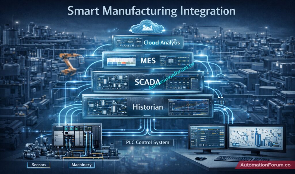
Smart manufacturing depends on connected data, not just connected devices. ControlLogix 5590 is positioned for that reality because it combines deterministic real-time control with industrial networking, built-in safety, and secure communication paths. Rockwell’s product positioning explicitly connects the 5590 to modern industrial environments that are more connected, data-driven, and performance-intensive.
Refer the below link for the Sinking and Sourcing: Which Connection is Best for Your PLC?
Integration with MES, SCADA, Historians and Cloud Layers
In an IIoT-oriented plant, the controller may need to do all of the following at once: execute machine logic, stream operational tags, provide diagnostics to maintenance, support secure integration with upstream systems, and keep the production line moving. The 5590’s EtherNet/IP, OPC UA, and cybersecurity features make it a strong fit for that architecture.
It also fits well with PlantPAx-style architectures. Rockwell explicitly notes integrated safety and redundancy support for scalable PlantPAx systems, which is important for process plants that want a consistent control platform across unit operations, utilities, and batch/process areas.
For process industries such as oil & gas, chemical, power, and batch operations, the 5590 is attractive because it unifies process control, safety, and redundancy in one modular platform. Rockwell’s documentation lists process and batch control, Logix SIS architecture, and redundancy support as the main application cases.
A chemical unit is a good example. The controller has to handle pumps, valves, analyzers, and interlocks while also enabling safe shutdown logic and secure connections with the plant network. In that kind of environment, the 5590’s safety partner option and Logix SIS pathway are especially useful.
ControlLogix 5590 for Discrete Manufacturing
For discrete manufacturing, the strongest fit is in robotics, packaging, material handling, and high-speed assembly. Rockwell specifically cites robotics, packaging, and high-speed systems as motion-heavy application areas, and the 512-axis ceiling shows the platform is built for scale.
Best Use Cases in Robotics, Packaging and Batch Systems
A packaging line, for example, may need coordinated servo axes, safety doors, recipe management, and line diagnostics. Instead of splitting those tasks across multiple control systems, the 5590 lets engineers consolidate them into a single high-performance architecture.
ControlLogix 5590 is designed for the Studio 5000 Logix Designer ecosystem, and Rockwell states that it can also be designed efficiently using FactoryTalk Design Studio. That matters because engineering teams are increasingly expected to work with modern tools that support collaboration, reuse, and faster commissioning.
FactoryTalk Logix Echo for Simulation and Testing
Rockwell also highlights FactoryTalk Logix Echo for accelerating deployment through simulation and validation before field commissioning. That is valuable when controls teams want to catch logic, sequence, and integration issues before hardware is energized.
For engineers, the benefit is threefold: faster development, safer testing, and easier lifecycle maintenance. The controller family is explicitly intended to reduce engineering overhead and simplify complex automation challenges, which is a strong fit for plants that need repeatable standards across multiple lines or units.
The biggest advantage is system consolidation. Because the platform combines safety, motion, process control, and communications, engineers can reduce the number of separate controllers and network islands in a plant. That generally simplifies drawings, FAT/SAT, spare parts, and troubleshooting.
Faster Commissioning and Better Diagnostics
Another advantage is diagnostics and commissioning speed. Rockwell emphasizes faster scan times, secure data flow, enhanced troubleshooting, and design tools that reduce time to commission. In plant maintenance terms, that often translates into faster fault isolation and better visibility across the system.
Scalability for Future Expansion
Finally, the platform’s scalability is a long-term benefit. The same controller family can address standard, safety, redundancy, and Logix SIS needs, so engineering standards do not have to be reinvented every time the application changes.
The 5590 is a premium platform, so budget planning matters. In practice, the combination of safety, redundancy, dual 1 Gb Ethernet, and high memory capacity usually means you should treat the controller as a strategic platform choice rather than a low-cost replacement. That is an engineering inference from the feature set, not a quote from the vendor.
Learning Curve for Existing Logix Users
There is also a learning curve. Teams moving from older Logix platforms should plan for Studio 5000 version alignment, safety architecture decisions, network design, and controller migration validation. Rockwell’s documentation set for the 5590 includes separate resources for standard, security, redundancy, Logix SIS, and safety architectures, which is a good indicator that proper engineering discipline is required.
Compatibility and Migration Planning
Compatibility planning is another key consideration. Because the controller is modular and chassis-based, the migration path should be reviewed against existing I/O, communication modules, network topology, and plant standards before a cutover is scheduled.
The future of PLCs is moving toward tighter integration with digital engineering, secure connectivity, and real-time data exchange. Rockwell’s ecosystem already points in that direction through cloud-based design, controller emulation, and software-defined industrial automation tools.
Digital Twin and Edge-Connected Manufacturing
That is where ControlLogix 5590 fits: as a controller that bridges classic deterministic control with modern OT/IT expectations. Its support for OPC UA, EtherNet/IP, secure boot, and safety integration positions it well for edge-connected plants, digital twin workflows, and cybersecurity-conscious architecture.
Why the 5590 Is Built for the Future
In practical terms, the plants that win with this platform will be the ones that want fewer isolated controllers, more connected diagnostics, and a stronger path toward smart manufacturing without sacrificing control reliability. That is the strategic value of the 5590.
ControlLogix 5590 is Rockwell Automation’s next-generation Logix controller for demanding industrial environments. It combines high-performance processing, up to 80 MB memory, up to 512 motion axes, dual 1 Gb EtherNet/IP ports, embedded safety, redundancy options, OPC UA support, and IEC 62443-4-2-aligned cybersecurity. For engineers designing smart manufacturing systems, that is a powerful combination of performance, safety, and connectivity.
If your plant needs a smart manufacturing PLC that can handle motion, process, safety, and secure networking in one platform, the ControlLogix 5590 belongs near the top of the shortlist. Its biggest advantage is not just speed; it is the way it reduces architecture complexity while increasing capability.
Refer the below link for the Critical Flaw in Rockwell ControlLogix CVE-2024-6242 – Trusted Slot Bypass Vulnerability
What makes ControlLogix 5590 different from older ControlLogix controllers?
The 5590 adds more memory, more motion capacity, dual embedded 1 Gb Ethernet ports, stronger built-in safety, and broader communication support than the earlier 5580 generation.
Does ControlLogix 5590 support functional safety?
Yes. Rockwell states that every controller variant includes SIL 2 / PLd safety, and SIL 3 / PLe is achievable with a safety partner.
Can ControlLogix 5590 be used in redundant systems?
Yes. Rockwell provides redundancy architecture resources for the family and states that the controller is configurable for redundancy and Logix SIS applications.
What is the difference between ControlLogix 5590 and 5580?
ControlLogix 5590 has more memory (up to 80 MB), two 1 Gb Ethernet ports, and support for 512 axes. ControlLogix 5580 has less memory (up to 256 axes), one Ethernet port, and support for 256 axes.
Is ControlLogix a PLC or PAC?
ControlLogix is considered a Programmable Automation Controller (PAC) because it combines PLC reliability with advanced features like motion, safety, and data integration.
What is ControlLogix?
ControlLogix is a modular industrial controller platform from Rockwell Automation used for process, discrete, and safety control in modern automation systems.
Closed Tank Level Measurement Troubleshooting Quiz for Process Industry Professionals
When the process is pressured, wet, foamy, or very changeable, it can be hard to measure the level in a closed tank. When troubleshooting level transmitters in real plants, it often starts with symptoms that seem simple but are actually caused by impulse lines, vapor space effects, density fluctuations, or bad installation. This advanced quiz assesses your ability to make good decisions about DP level measurement, radar level transmitter behavior, displacer level measurement, and chamber problems. Each scenario is based on what really happens in refineries, chemical units, power stations, and water process plants. Use it to test your ability to fix instrumentation problems and make better maintenance decisions when you’re under pressure and on a tight timetable.
Test Your Level Transmitter Troubleshooting Skills in Real Process Scenarios
Why Safety Instrumented System Design Mistakes Matter in Process Industries
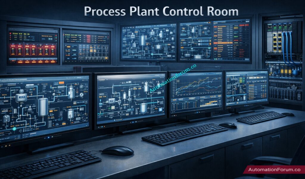
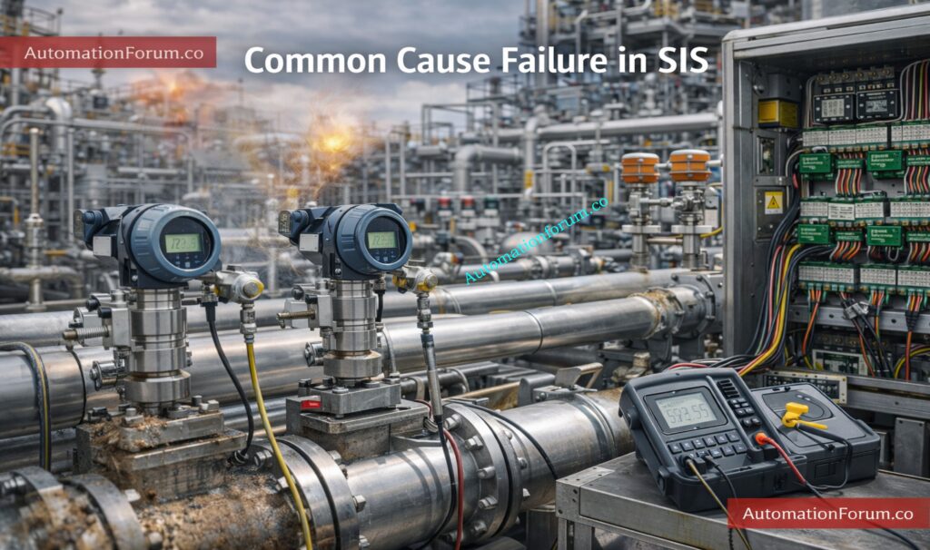
Safety Instrumented Systems (SIS) are a critical layer of protection in process industries such as oil & gas, petrochemicals, chemicals, refining, and power generation.
Their main purpose is to detect hazardous process conditions and drive the plant to a safe state before a serious incident occurs.
Even a well-funded project can fail if the SIS is designed poorly, tested inadequately, or maintained without discipline.
Safety Instrumented System design mistakes often happen during early engineering, especially when the team treats functional safety as a documentation task instead of a lifecycle activity.
Standards such as ISA 84 standard guidelines and IEC 61511 SIS design provide a structured framework to reduce risk, improve traceability, and support safe operation.
Most of the time, the main problem isn’t that there aren’t any standards. It’s that they aren’t being followed well, that different fields aren’t working together well, and that designers and builders are taking shortcuts.
A single SIS failure can cause damage to equipment, discharge of chemicals into the environment, loss of production, and even death in the worst circumstances.
That is why engineers must understand both the technical and practical side of SIS design, including SIL verification, proof testing, independence, and lifecycle management.
Safety Instrumented System design flaws are mistakes made when designing, building, or maintaining SIS that make it less effective in stopping dangerous events.
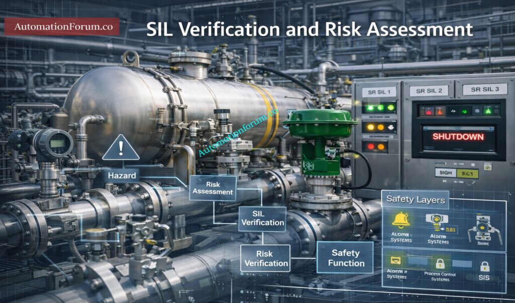
SIL, or Safety Integrity Level, is one of the most important outputs of the risk assessment process.
Why SIL Is Critical in SIS Design
It defines the level of risk reduction required from the SIS.
Incorrect SIL assignment can lead to:
Underprotection of the process
Unnecessary complexity
High cost without real safety benefit
How ISA-84 Supports Functional Safety Compliance
ISA-84 standard guidelines enforce:
ISA 84 is important because it turns functional safety into a disciplined engineering process rather than an informal design practice.
For instrumentation and control engineers, this means every design choice must be traceable back to risk, operating conditions, and lifecycle requirements.
Top Critical Mistakes in Safety Instrumented System Design
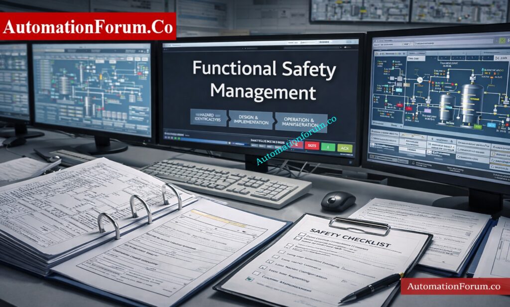
Poor Functional Safety Management (FSM)
One of the most serious functional safety management errors is failing to define clear ownership for SIS-related tasks.
Common Issues:
Common symptoms include:
No formal functional safety plan
Unclear responsibility between operations, maintenance, engineering, and EPC teams
Incomplete competency records
Weak review and approval process
Without FSM, the SIS becomes vulnerable to design gaps, uncontrolled changes, and inconsistent implementation.
In many projects, the design intent is understood by one team, but the installation and maintenance teams never receive the full context.
This creates hidden risks that only appear during a trip or audit.
Real Example:
In a lot of EPC projects, SIS design is outsourced without clear FSM ownership, which leads to SRS that aren’t always the same and designs that don’t match.
How to Avoid:
To avoid this:
Give each person defined jobs and duties
Make sure that staff members are schooled in the ideas of functional safety.
Incorrect SIL Assignment and SIL Verification Errors
When teams rush through the risk assessment stage or depend on assumptions instead of formal analysis, they often make mistakes when calculating SIL.
Common Errors:
Some common mistakes are:
Studies of HAZOP or LOPA that are not strong
Taking SIL values from other plants without a good reason
Not checking that the chosen SIL really does lower the risk as planned
Doing verification too late, after the equipment choice has already been made
Risks:
Choosing the wrong SIL causes two big problems:
Underdesign, which means the system doesn’t lower risk enough
Overdesign, which makes the system hard to maintain and costly
A badly checked SIL can also give people false confidence, which is especially dangerous because it looks like the plant is safe on paper but isn’t in real life.
How to Avoid:
To avoid this:
Follow a strict methodology for assessing hazards and risks
Check SIL early on in the design process
Check the assumptions that were used to figure out the chances of failure
Check verification again every time the system architecture changes.
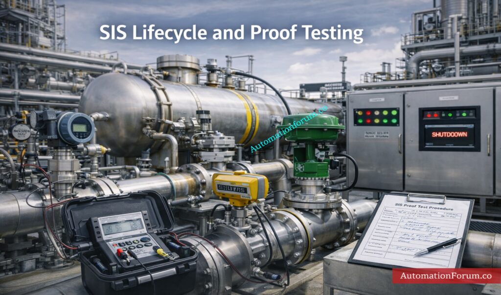
Ignoring the SIS Lifecycle Approach
One big reason for SIS lifecycle problems is thinking of SIS as a separate design package.
This happens a lot when safety design, process design, and control design are all done separately.
Common Mistakes:
Some common problems are:
Not being able to trace from hazard analysis to SRS
Not having a proof test approach during design
No thought given to how easy it is to maintain
Poor preparation for bypasses, overrides, and changes that will happen in the future
Impact:
Without lifecycle thinking, the SIS can work OK at first but stop working over time.
This causes long-term damage, bad audit findings, and trouble proving compliance.
Solution:
To avoid this:
Connect each safety criterion to a certain risk situation.
Harsh environmental conditions affecting every channel
Calibration Example:
A practical example is calibration error: if all redundant sensors are calibrated using the same incorrect reference or procedure, redundancy does not help.
Another example is using the same devices in the same process environment without taking into account things like vibration, corrosion, or heat that can cause stress.
Prevention:
To avoid this:
Separate superfluous parts from one another physically
Think about different technologies when it’s appropriate
When you can, don’t use shared utilities.
Early on, look at common cause concerns that have to do with the environment and upkeep.
It’s not enough to only choose safety-rated hardware when designing a reliable SIS.
It takes focused thinking about the whole life cycle, good management of functional safety, and close attention to how things really are at the facility.
Most Safety Instrumented System design mistakes come from weak verification, poor proof testing, common cause failures, and missing documentation.
Engineers who understand ISA 84 standard guidelines and apply them consistently can greatly reduce risk and improve plant reliability.
A strong SIS is one that works not only during commissioning, but also after years of operation, maintenance, and modification.
The best way to prevent repeated industry failures is to treat functional safety as an ongoing engineering responsibility, not a one-time project deliverable.
Frequently Asked Questions About Safety Instrumented System Design
What are the most common SIS design errors?
Common SIS design errors include incorrect SIL assignment, weak functional safety management, lack of independence from BPCS, and poor proof testing practices. These issues reduce system reliability and can lead to unsafe conditions during real process upsets.
Why is ISA-84 important for SIS design?
ISA-84 (aligned with IEC 61511) provides a lifecycle-based framework for designing, implementing, and maintaining Safety Instrumented Systems. It ensures consistent risk reduction, proper documentation, and long-term functional safety compliance.
A common cause failure occurs when multiple redundant components fail due to a shared dependency like power supply, environment, or calibration error. This defeats redundancy and significantly reduces the effectiveness of the SIS protection layer.
How often should SIS proof testing be done?
SIS proof testing frequency is defined based on SIL requirements and probability of failure (PFD) calculations. Intervals must follow the Safety Requirements Specification (SRS) to ensure the system maintains its required integrity.
Safety Integrity Level (SIL) defines the required risk reduction level for each Safety Instrumented Function (SIF). It ensures the SIS performs reliably enough to meet process safety targets.
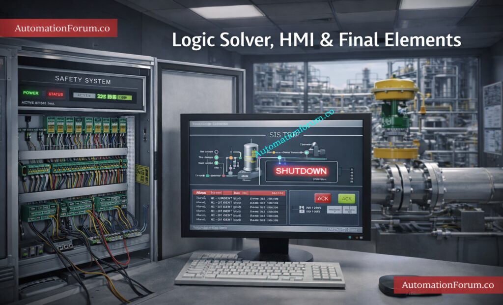
What are the final elements in safety instrumented systems?
Final elements are devices that take action to bring the process to a safe state, such as shutdown valves, relays, or motor trips. They receive signals from the logic solver and physically execute the safety action.
What is the standard for safety instrumented function?
Safety Instrumented Functions (SIFs) are governed by IEC 61511 (process industry) and IEC 61508 (generic functional safety standard). These standards define requirements for design, SIL assignment, and lifecycle management.
What must a safety instrumented system do?
A Safety Instrumented System must detect hazardous conditions and automatically bring the process to a safe state. It performs this by sensing, decision-making, and acting through sensors, logic solvers, and final elements.
Refer the below link for Understanding Zener vs Galvanic Isolation in IS Loops for 4 to 20 mA Systems
Introduction to Control Valve Selection in Process Industries
Why Control Valve Selection is Critical for Process Performance
Picking the right control valve in process industries is a big technical decision that affects how well the complete plant works, how efficiently it runs, and how reliable it is.
Impact of Valve Selection on Energy Efficiency and System Stability
Valves are more than just mechanical parts; they have a direct effect on:
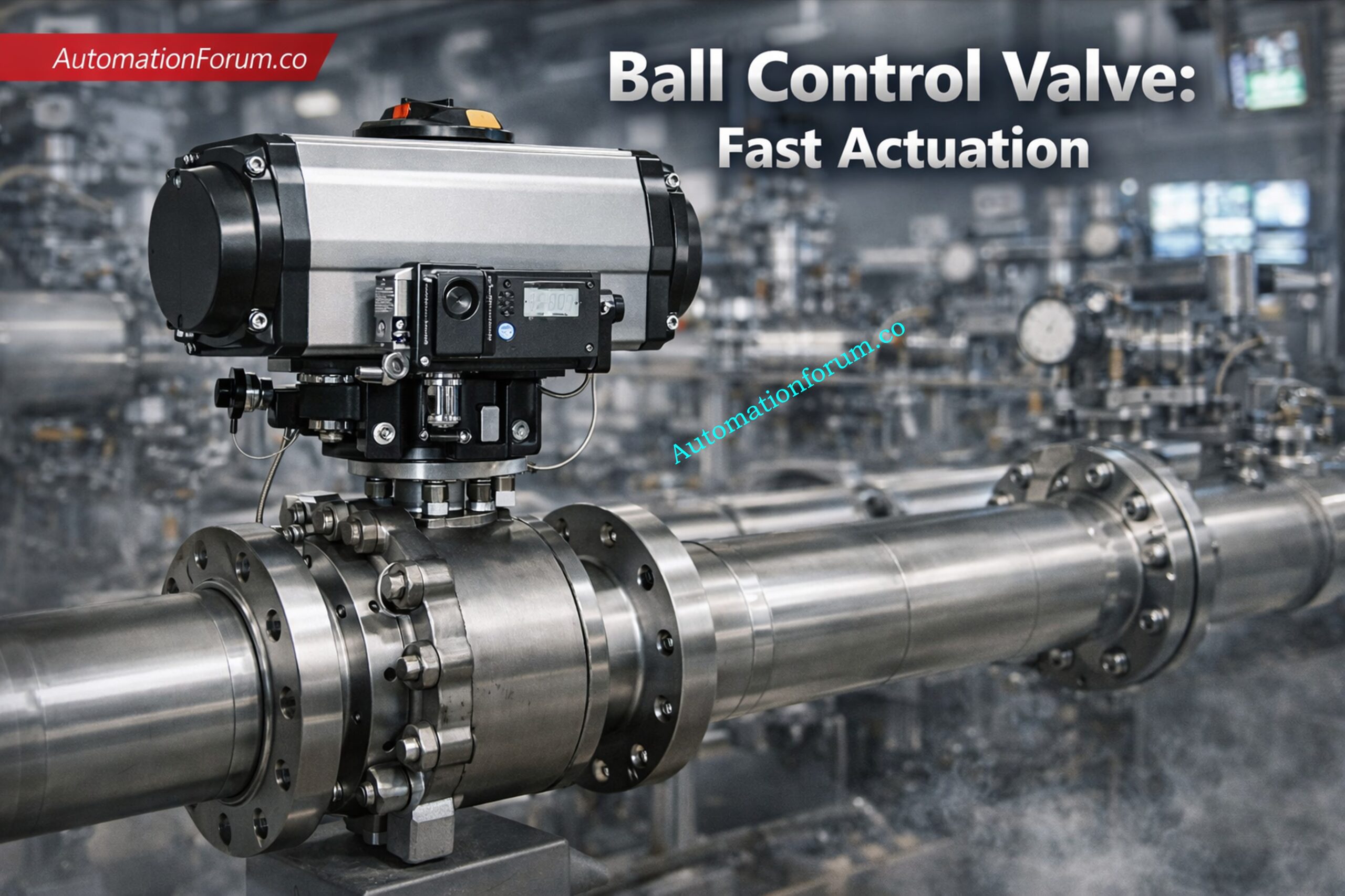
Throttling vs On Off Valve Applications in Process Industries
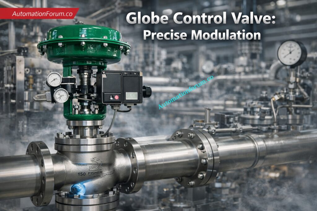
Why Globe Valves are Best for Throttling Applications
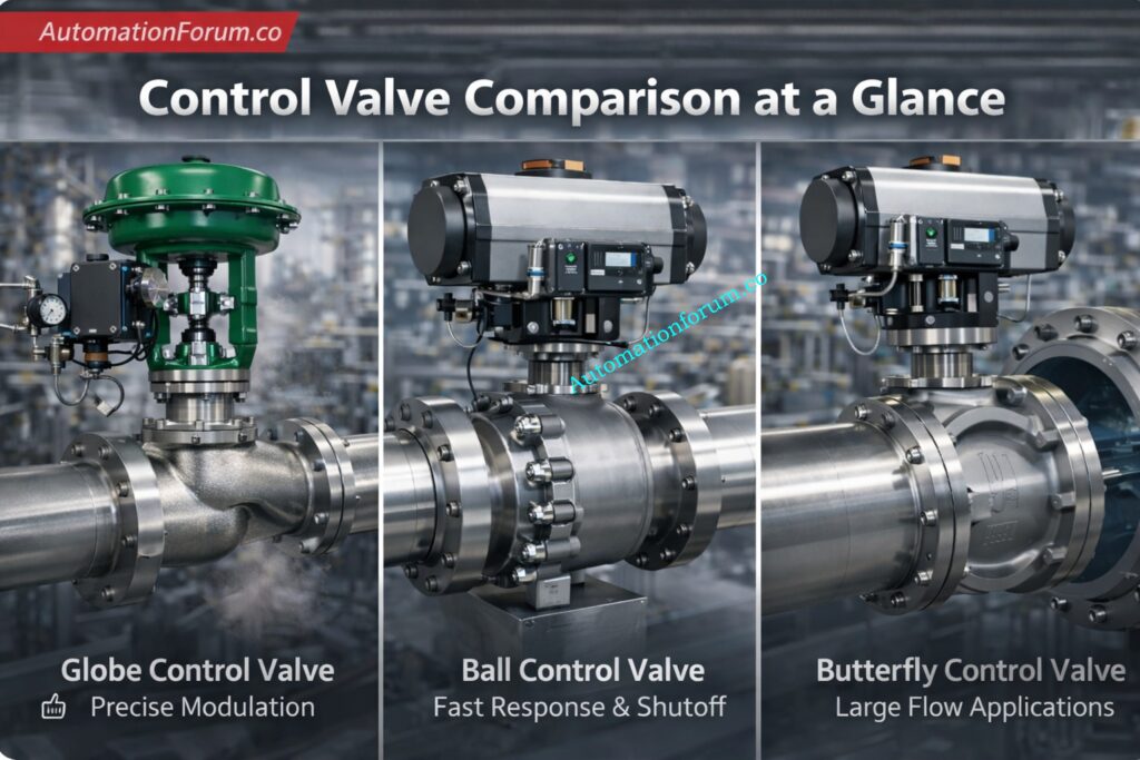
Globe valve is the preferred option because it provides smooth and continuous flow modulation where the valve position directly controls flow rate.
It makes sure that Cv control is precise, so that flow varies in direct proportion to valve travel. This lets you size things correctly and know how they will work.
Keeps the control loop behavior consistent, which cuts down on oscillations, hunts, and problems with PID tuning that happen too often.
Cv Characteristics and Flow Behavior in Different Valve Types
Globe valves have Cv characteristics that are steady and predictable. This means that flow changes in a way that is proportionate to the valve position, which makes control easier.
Ball valves have very high Cv values, which means they can handle a lot of flow, however they don’t work well when they are just partially open since the flow suddenly increases.
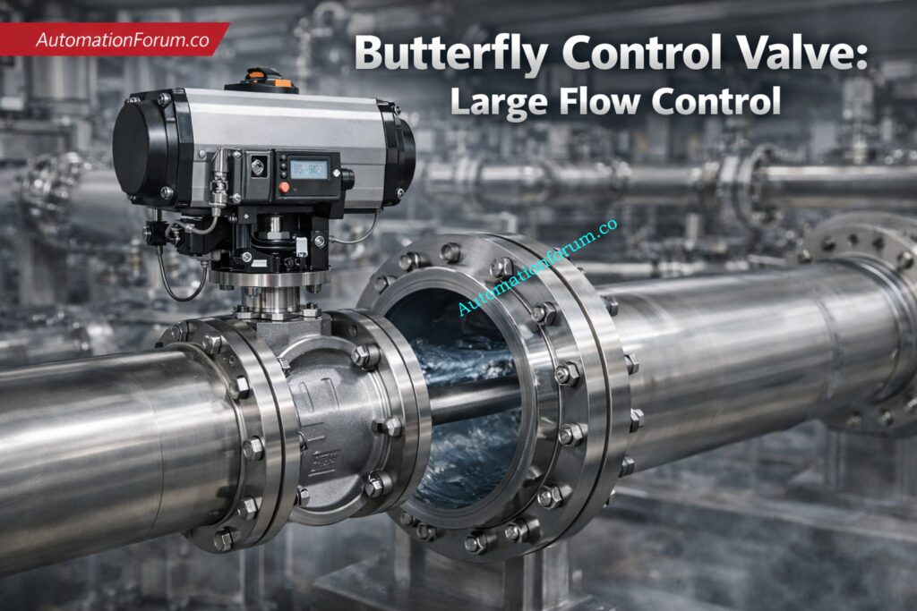
Butterfly valves have a moderate Cv and behave in a non-linear way, which makes them good for mid-range control but not for precision applications.
Flow characteristic curves like linear, equal percentage, and rapid opening tell control valves how to work. These curves show how the valve position affects the flow rate.
Quick opening is usually utilized for on-off applications, while linear and equal percentage are employed for throttling.
A greater Cv means a bigger flow capacity but a lesser control resolution.
A lower Cv means that the system is easier to operate, but it also means that the pressure drop is higher.
Choosing the right Cv is very important for sizing valves, making control loops work better, and making the whole system work better.
Pressure Drop and Energy Efficiency in Control Valves
Flow Path Impact on Pressure Drop in Globe Ball and Butterfly Valves
Because the flow direction changes a lot, the globe valve creates a lot of turbulence, which makes it hard to go through the valve.
The S-shaped flow route makes friction losses and energy loss happen more often while the machine is running.
The ball valve lets full-bore flow go right through, which reduces blockages and keeps flow conditions close to those of a pipe.
This straight approach makes the system more efficient by reducing turbulence and head loss.
The disc of a butterfly valve makes it impossible for the valve to be fully open.
The disc causes some turbulence and flow separation, which makes the pressure drop.
The way the flow behaves has a direct effect on pressure drop, energy use, and system performance.
More turbulence makes it easier to regulate things, but it makes them less efficient. Less turbulence makes things more efficient, but it makes them less precise.
An IS barrier earth fault current calculator is a tool used to evaluate intrinsic safety loops by calculating fault current, verifying grounding, checking gas group compatibility, and ensuring hazardous area compliance.
What is an IS Barrier Earth Fault Current Calculator?
An IS barrier earth fault current calculator is a useful engineering tool used to evaluate the safety of an intrinsic safety loop in a hazardous area. It helps instrumentation engineers, electrical engineers, and maintenance teams check whether the selected zener barrier or galvanic isolator is suitable for the application, whether the earth conductor size is adequate, and whether the fuse rating is properly selected for safe operation.
In process industries, intrinsic safety is one of the most important protection methods for equipment installed in explosive atmospheres. A small error in barrier selection, grounding, gas group matching, or conductor sizing can create a serious safety risk. That is why using an IS barrier calculator is valuable during loop design, commissioning, troubleshooting, and maintenance.
This calculator is especially helpful for engineers who need a quick but practical check of earth fault current, zone compliance, gas group compatibility, and fault protection in hazardous area instrumentation loops.
Why IS Barrier Earth Fault Current Calculation Is Important
The calculation of earth fault current in intrinsic safety circuits is important because the earth conductor and protective devices must be able to handle abnormal fault conditions safely. In a zener barrier system, the earth path is a critical part of the protection concept. If the earth conductor is undersized, incorrectly installed, or poorly connected, the safety barrier may not perform as intended.
For this reason, an intrinsic safety earth fault current calculator supports safer design decisions by helping to identify:
Whether the loop current is within a safe range
Whether the selected barrier type matches the hazardous area requirement
Whether the earth conductor can withstand the calculated fault current
Whether the fuse rating is appropriate for the loop
Whether the barrier gas group is suitable for the area gas group
Whether the selected setup meets the required hazardous area classification
This makes the calculator a practical tool for both design verification and field maintenance.
The attached calculator is straightforward, but every input represents an engineering decision. The idea is to enter the real loop data, not just default values.
Barrier type
Select Zener Barrier or Galvanic Isolator.
A zener barrier depends on a sound earth reference to divert fault energy safely. A galvanic isolator provides isolation through electronics and transformer-based or similar methods, which changes the grounding requirement. This selection affects the current calculation method in the attached logic.
Hazard zone
Choose the area classification: Zone 0, Zone 1, or Zone 2.
This matters because not every barrier arrangement is acceptable in every zone. In the attached logic, the zone check flags galvanic isolator use as not permitted in Zone 0. That makes the calculator useful as an advisory screening tool before final design review.
Gas group of area
Select the site gas group: IIA, IIB, or IIC.
This represents the severity of the flammable atmosphere. A gas group mismatch can invalidate the protection concept even if the loop current looks acceptable.
Gas group of barrier
Enter the barrier gas group.
The calculator checks whether the barrier gas group is equal to or more robust than the area gas group. In practice, that is one of the first things to confirm during intrinsic safety review.
For a zener-style calculation, voltage contributes to the available current. In the attached logic, voltage and resistance are used to estimate current when galvanic isolation is selected.
Resistance
Enter the loop resistance.
This helps determine the single-channel current when the calculator uses the voltage/resistance method.
Isc
Enter the short-circuit current value, usually in mA.
For the zener barrier path in the attached calculator, Isc is used directly as the single-channel current. That reflects a practical fault-current-oriented approach.
Loop current
Enter the normal operating loop current.
This is important for fuse recommendation and for checking whether the field loop operates within expected current demand.
Number of channels
Enter the number of channels in the barrier or isolator arrangement.
The calculator multiplies channel current by the number of channels and fault factor to estimate total fault current. That is useful when a multi-channel unit is feeding several loops.
This gives a margin for practical fault conditions. In plant work, that margin is important because real installations are never perfectly ideal.
Clearing time
Enter the clearing time in seconds.
This is used in the earth conductor sizing calculation. A longer clearing time generally increases the conductor size requirement.
Conductor material
Choose Copper or Aluminium.
The attached logic uses different k-values for the adiabatic sizing equation depending on the conductor material. That means conductor material directly affects the earth conductor size result.
Selected fuse
Enter the fuse rating in mA.
The calculator compares the selected fuse to a recommended value based on loop current. This helps flag under-rated protection before field installation.
The output is where the calculator becomes especially useful for engineering review.
Single channel current
This is the current for one channel based on the selected barrier type and input values. For zener barriers, the calculator uses Isc. It uses voltage split by resistance, which is then turned into mA, for galvanic isolators.
This is the expected fault current after considering number of channels and fault factor. In plant terms, it helps you think about worst-case stress on earthing and protection components.
Earth conductor size
This is one of the most important results. The calculator uses an IEC adiabatic-style equation and applies a minimum size rule. That helps ensure the earth conductor can survive fault energy long enough for protection to operate.
Gas group check
This result tells you whether the selected barrier gas group is suitable for the area gas group. In intrinsic safety, gas group compatibility is not optional; it is central to the protection concept.
Zone compliance
This result checks whether the chosen barrier arrangement is acceptable for the selected hazardous zone. In the attached logic, galvanic isolators are flagged as not suitable for Zone 0.
The calculator recommends a fuse rating based on loop current, then compares it with the selected fuse. In maintenance terms, this is useful when verifying that a replacement fuse has not altered the protection margin.
Overall status
The overall status is shown as either SAFE (Advisory) or CHECK REQUIRED. Engineers should treat this as a screening result, not a final certification. Final design still has to follow the applicable project specification, local code, and approved hazardous area documentation. That is especially important when applying IEC 60079 series requirements in real plant work.
IEC 60529: Enclosure protection, when panel or field enclosure protection is part of the review.
IEC 61508 / IEC 61511: Functional safety context, where loop protection interacts with safety instrumented systems.
NEC / NFPA 70 Articles 500 and 504: Useful when comparing North American hazardous area practice.
ATEX concepts: Important for Europe-based hazardous area compliance.
These standards matter because they shape barrier selection, grounding practices, installation quality, and inspection expectations. They don’t take the role of project-specific technical judgment; instead, they set the rules for how the loop should be established and kept up.
Key Benefits of Using an IS Barrier Earth Fault Current Calculator
Using an IS barrier earth fault current calculator provides several practical benefits for engineers working in process industries, oil and gas plants, chemical plants, and other hazardous environments.
Faster Loop Design Review
The calculator gives a rapid engineering view of the loop instead of having to check each value by hand. This saves time during the design process and helps find problems early.
Better Hazardous Area Compliance
The calculator may check for zone compliance, gas group compatibility, and the right way to safeguard people, all of which are critical for compliance in hazardous areas.
Improved Maintenance Verification
Maintenance teams can use the calculator to recheck the loop after a barrier replacement, cable change, fuse replacement, or grounding modification.
This calculator is practical for teams involved in both design and ongoing plant support.
Design engineers
Use it while preparing IS loop design packages, selecting barriers, sizing earth conductors, and checking whether the proposed loop is compatible with the hazardous area classification.
Instrumentation engineers
Use it when choosing a barrier for transmitters, switches, solenoids, or other low-energy field devices and when confirming the loop against project standards.
Maintenance engineers
Use it during repair, replacement, periodic checks, and troubleshooting of existing intrinsic safety loops, especially if a barrier, fuse, or cable has been changed.
Before selecting a zener barrier or galvanic isolator
A zener barrier usually depends heavily on proper earthing. A galvanic isolator changes the grounding philosophy, so this check helps avoid mismatches early.
Before finalizing earth conductor size
The calculator’s conductor sizing result is useful when deciding whether the earth conductor is adequate for the expected fault current and clearing time.
During maintenance checks and troubleshooting
Use it when loops show nuisance faults, unstable readings, or grounding-related issues.
When verifying fuse and protection settings
Fuse selection should be checked whenever loop current, barrier protection, or wiring changes are made.
Frequently Asked Questions on IS Barrier Earth Fault Current
What is the difference between a zener barrier and a galvanic isolator?
A zener barrier relies on earthing to divert excess energy, while a galvanic isolator provides electrical isolation. The calculator helps compare both options in a practical IS loop context.
Why does earth fault current matter?
Because the earth path must be able to carry fault energy safely until protection operates. If the conductor is undersized, the protection concept becomes weak.
Yes. A zener barrier must be properly grounded to a dedicated intrinsic safety (IS) earth. Grounding safely diverts fault energy and prevents sparks. Without proper grounding, the intrinsic safety protection can fail.
What is the earth fault current?
Earth fault current is the current that flows to ground during a fault condition. It occurs when a live conductor contacts earth or grounded parts. This current is critical for protection system design and safety.
Is the earth an effective ground fault current path?
Yes, but only if the earth path is low resistance and properly designed. In intrinsic safety systems, a dedicated IS earth is required.
Poor grounding can lead to unsafe conditions and protection failure.
Which is better: Zener barrier or galvanic isolator?
It all relies on the application and how it is set up.
Zener barriers are cheap, but they need robust grounding. Galvanic isolators are safer where proper grounding is difficult.
Galvanic isolation is a method, not a type of supply (AC/DC). It can be used in both AC and DC systems depending on design. Most industrial isolators work with DC signal loops.
What is the difference between barrier and isolator?
A barrier limits energy entering a hazardous area and needs grounding. An isolator provides electrical separation without relying on earth. Isolators offer better noise immunity and flexible installation.
Is this calculator suitable for Zone 0, Zone 1, and Zone 2?
It is useful as an advisory tool for all three zones, but the attached logic flags galvanic isolator use as not permitted in Zone 0. Final suitability still depends on project and code requirements.
Why is fuse sizing important?
The size of the fuse influences how well it protects the loop and how well it can remove errors. The calculator looks at the chosen fuse and compares it to a suggested value depending on the loop current.
How do international standards influence IS loop design?
Standards such as IEC 60079-11, IEC 60079-14, and IEC 60079-17 define the framework for safe equipment selection, installation, and inspection in hazardous areas.
The IS barrier earth fault current calculator is a practical tool for engineers who work with intrinsic safety, hazardous area instrumentation, and process automation systems. It brings together the core checks that matter in real plant work: barrier type, zone suitability, gas group compliance, earth fault current, conductor sizing, and fuse selection. The attached calculator also reflects the way engineers actually work in the field, where design review and maintenance troubleshooting often overlap.
For design engineers, it helps reduce loop-design errors before installation. For maintenance teams, it provides a quick way to verify whether a modified loop still makes sense from an intrinsic safety point of view. Used correctly, it supports safer decisions, cleaner documentation, and better alignment with IEC 60079-based hazardous area practice.
Engineering takeaway: treat the calculator as a disciplined first check for IS loop protection, then complete the final review against project specifications, local code, and approved hazardous area documentation.
Refer the below link for What is HAZOP Study in Instrumentation Engineering for EPC Engineers in Process Industries
What Is a Differential Pressure Switch and How Does It Work?
Differential pressure switch working principle
A differential pressure (DP) switch is a tool that tells you how different two pressure points are. The high-pressure (HP) side and the low-pressure (LP) side are the two pressure points that are usually measured. The switch turns on or off an electrical contact based on this differential in pressure. This can set off alarms, trips, or control activities.
How A Dp Switch Measures High Pressure And Low Pressure
The DP switch operates using a diaphragm or piston mechanism. The difference in pressure between HP and LP makes a force that moves the detecting element, which then turns on an electrical switch. A spring mechanism is used to change the setpoint.
DP switch applications in process industries
Filter Monitoring: Measures the pressure drop across filters to find out if they are clogged.
Flow Detection: Used with orifice plates to make sure there is flow
Level Measurement: Using pressure differential in closed tanks
HVAC Systems: keep an eye on airflow and duct pressure.
Safety Interlocks & Alarms These systems go off when pressure changes.
Why Differential Pressure Switch Calibration is Required
Accuracy, Safety and Operational Reliability
Calibration makes ensuring that the DP switch works correctly, consistently, and safely, which is especially important for safety-critical systems like SIS (Safety Instrumented Systems).
Verifying Set Point, Reset Point and Deadband
Check the precision of the setpoint
Check the reset point
Find the deadband (hysteresis)
Make sure the switching works right
IEC 61511 and Calibration Practice Considerations
IEC 61511: Making sure things work safely in process industries
ISA Calibration Practices: Standard methods for the industry
ISO/IEC 17025: Quality and traceability of calibration
Calibration makes sure that the device works within safe limits and keeps the process safe.
The calibration setup is the foundation of accurate differential pressure switch calibration. If the setup is incorrect, even a perfectly executed procedure will produce wrong results. In real plant conditions, most calibration errors are not due to the instrument itself but due to improper setup, trapped pressure, or incorrect connections.
A differential pressure switch works based on the pressure difference between two points. Therefore, the calibration setup must simulate this pressure difference correctly.
In most field activities, the low-pressure side is left open to the air. This procedure makes it easier to calibrate and is often used for regular maintenance and checks.
Completion of Differential Pressure Switch Calibration
After the differential pressure switch has been successfully calibrated, put a label on it that shows the date of calibration, the due date, and the name of the technician.
After that, the calibration setup needs to be carefully ventilated and let go of its pressure. This is crucial so that there isn’t any leftover pressure in the high-pressure side lines.
Carefully unplug all testing equipment from the high pressure port and make sure that the low pressure side, which was open to the air during calibration, is correctly locked.
Make sure that the area where you work is clean and doesn’t have any tools, tubing, or fittings that were used during calibration.
De isolate the differential pressure switch from the test condition and restore it back to process condition.
Bring back any signals that were bypassed or inhibited during calibration to their normal operating state.
Slowly open isolation valves and restore the impulse lines.
Bring the differential pressure switch back online and return it to normal operation.
The image that follows represents a typical differential pressure switch calibration report, which includes set point and reset point recorded during calibration.
The calibration of a differential pressure switch in field conditions is typically performed by keeping the low pressure side open to atmosphere and applying pressure on the high pressure side.
The method includes
Proper isolation
Correct setup
Controlled pressure application
Accurate recording of set and reset points
Verification and adjustment
A organized and disciplined methodology makes sure that the calibration is correct and the plant runs safely.
Frequently Asked Questions About Differential Pressure Switch Calibration
How often should a DP switch be calibrated?
You should calibrate a differential pressure switch once a year or according to the plant’s maintenance schedule. Depending on the risk of the process and the conditions in which it is running, critical safety applications may need to be calibrated more often.
Why is the low pressure side kept open to atmosphere?
The low pressure side is maintained open to the outside world to make a reference pressure of zero. This makes it easy to make differential pressure with just the high side. This makes it easier to calibrate in the field and makes setups more accurate.
What is deadband in a differential pressure switch?
The difference between the switch’s set point and reset point is called the deadband. It prevents frequent switching and ensures stable operation by introducing a small gap between ON and OFF actions.
Can a DP switch be calibrated in situ?
Yes, you can calibrate a DP switch in place if it is appropriately isolated, depressurized, and safe to get to. However, it is important to eliminate process interruptions and make sure that the test circumstances are correct.
Do differential pressure sensors need calibration?
Yes, differential pressure sensors need to be calibrated on a regular basis to keep their accuracy, dependability, and safety performance. Over time, drift and the parameters of the operation can change how measurements and switches work.
Refer the below link for the Free Instruments Calibration Procedures: 60+ Step-by-Step Methods for Pressure, Temperature, Flow & Level