- Analog Signals in Industrial Process Control
- Understanding Analog Signals in Process Instrumentation
- Common Process Variables Measured Using Analog Signals
- Common Analog Signal Standards Used in Industry
- What Is the Dead Zero Problem in Analog Signals
- Why the Dead Zero Problem Is Critical in Process Industries
- Dead Zero Versus Live Zero Explained Clearly
- Live Zero 4 to 20 mA Loop Concept and Wiring Overview
- Why 4 to 20 mA Became the Industry Standard
- Real Process Industry Examples of the Dead Zero Problem
- Dead Zero Issues in Voltage Based Analog Signals
- Dead Zero Problems in Voltage Based Analog Signals
- Dead Zero During Commissioning, Maintenance and Safety Systems
- Role of Dead Zero in Safety Instrumented Systems
- Importance of Dead Zero Awareness for Control Room Operators
- Dead Zero Considerations in Modern Digital Instrumentation
- Long Term Operational and Cost Impact of Dead Zero Signals
- EPC and Instrumentation Design Perspective on Dead Zero
- Situations Where Dead Zero Signals Still Exist in Plants
- Best Practices to Avoid the Dead Zero Problem
- Why Live Zero Signaling Is Essential for Safe and Reliable Plants
- FAQ on dead zero problem in analog signal
Analog Signals in Industrial Process Control
Analog signals continue to be the backbone of measurement and control in process industries such as oil and gas, chemical processing, power generation, pharmaceuticals, water treatment, cement, steel, and pulp and paper plants. Even with the increasing adoption of digital protocols and smart field devices, analog signals remain the most widely used and trusted method for transmitting real time process variables from the field to control systems.
Twisted pair cables explained for industrial signal transmission: Twisted Pair Cable in Industrial Signal Transmission: The Essential Guide for 4-20 mA and RS 485 Systems
Importance of Analog Signals in Measurement and Control Systems
The dead zero problem is one of the most important yet often underestimated problems in analog instrumentation. This problem has a direct impact on the safety of the process, the accuracy of the controls, the effectiveness of the alarms, the speed of commissioning, and the ease of troubleshooting maintenance. Instrumentation engineers, EPC designers, commissioning teams, and plant operators all need to know about this problem.
This main article is written in a way that works well with Google Discover, is optimized for featured snippets, and is clearly structured for SEO performance. It is also technically correct and useful for real process plants.
Fix common 4–20 mA loop problems easily: 4-20 mA Loop Troubleshooting with Loop Calibrators : A Practical Guide
Understanding Analog Signals in Process Instrumentation
Analog signals are electrical signals that change over time to show how process factors are changing. These signals let transmitters change physical parameters into electrical values that control systems can understand.
Live zero versus dead zero clearly explained: Understanding the Difference Between Live Zero and Dead Zero in 4 to 20 mA Signals
Common Process Variables Measured Using Analog Signals
- Flow rate of liquids and gases
- Pressure and differential pressure
- Level in tanks and vessels
- Temperature in reactors and pipelines
- Valve position and actuator feedback
- Speed, density, and analytical measurements
Refer the below link for the Why 4-20 mA Current Signal is Preferred Over Voltage Signal in Instrumentation?
Common Analog Signal Standards Used in Industry
The most widely used analog signal standards include:
- 4 to 20 mA current signals
- Current indications from 0 to 20 mA
- Voltage signals from 0 to 10 volts
- Signals with voltages from 0 to 5 volts
In industrial settings, current-based signals are preferable because they are stronger, less affected by noise, and work well across lengthy wire lengths.
Calculate transmitter output from 4–20 mA signals: 4 to 20 mA Transmitter Output Process Value Calculator
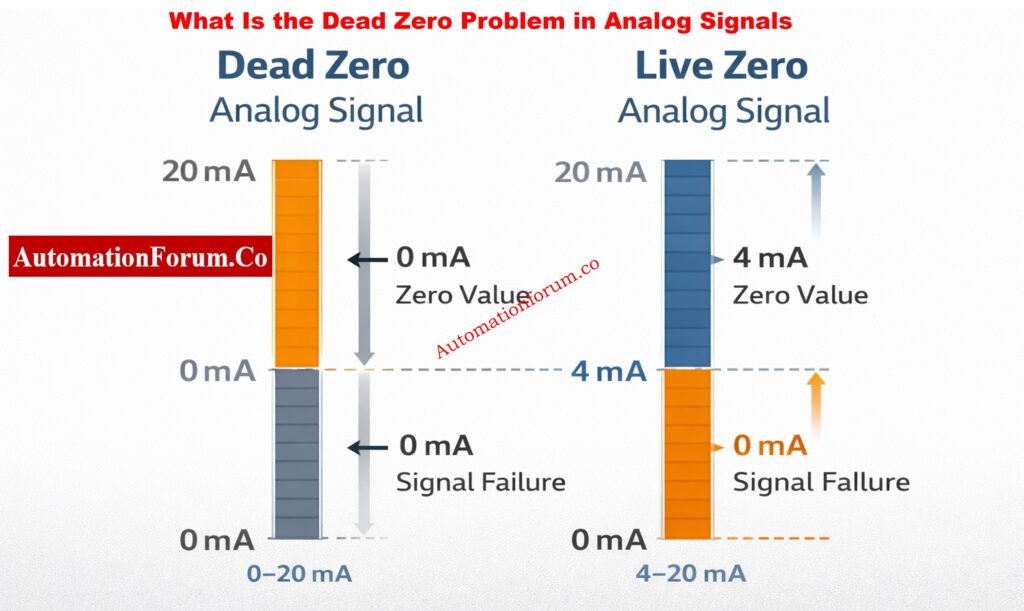
What Is the Dead Zero Problem in Analog Signals
Definition and Root Cause of Dead Zero
When the signal range starts at zero, the dead zero problem happens. This means that zero might mean both a good process condition and a signal failure situation.
In signal ranges such as 0 to 20 mA or 0 to 10 volt, a zero reading can indicate:
- The process variable is genuinely at zero
- The transmitter has lost power
- The signal cable is broken
- The analog loop is open
- The instrument has failed
Why Zero Cannot Indicate Instrument Health
Because all these situations produce the same zero output, the control system cannot distinguish between a healthy process measurement and an instrumentation fault. This ambiguity is known as the dead zero problem.
Convert frequency signals to accurate 4–20 mA: Frequency(Hz) to 4 to 20 mA Signal Conversion Calculator
Why the Dead Zero Problem Is Critical in Process Industries
In process plants, zero is rarely an insignificant value. Zero flow, zero pressure, or zero level can represent normal operation, shutdown conditions, or potentially dangerous states.
Impact on Process Safety
If a dead zero signal doesn’t work, operators can think the process is safe when it’s not. For example, a pressure transmitter failure may display zero pressure even though the line is still pressurized. This can expose maintenance personnel to serious hazards.
Impact on Control Performance
Control loops depend on accurate feedback. A dead zero signal can lead to:
- Control valves that move to dangerous places
- Pumps and compressors that don’t start or stop when they should
- Control loops that fluctuate or fill up
Impact on Alarm and Diagnostic Systems
Dead zero signals might make it hard to see when an instrument breaks. The control system may not turn on low alerts because it thinks the zero reading is correct.
Calculate LRV URV and span values easily: Transmitter Calibration Span, LRV and URV Value Calculator from Measured 4 to 20 mA
Dead Zero Versus Live Zero Explained Clearly
What Is a Dead Zero Signal
A dead zero signal starts its measurement range at zero. Zero has no diagnostic meaning and cannot indicate whether the transmitter is healthy or failed.
Examples include 0 to 20 mA and 0 to 10 volt signals.
What Is a Live Zero Signal
A live zero signal starts its range above zero. The most common live zero standard is 4 to 20 mA.
In a live zero system:
- 4 mA represents the minimum process value
- 20 mA represents the maximum process value
- Any value significantly below 4 mA indicates a fault

This simple shift allows immediate detection of signal loss, power failure, or transmitter malfunction.
Convert 4–20 mA signals to 3–15 psi: 4–20 mA to 3–15 psi Signal Conversion Calculator
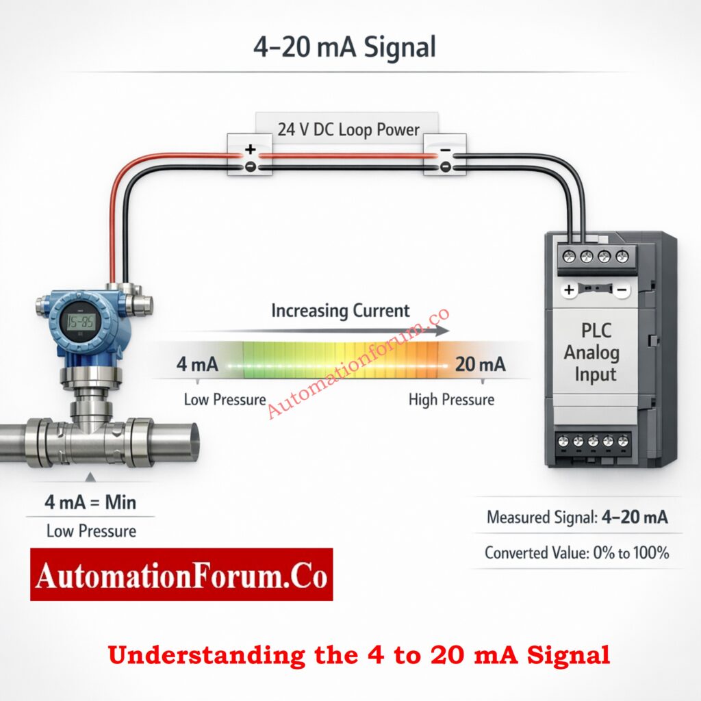
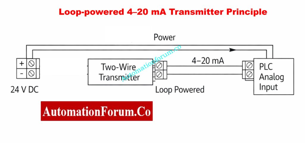
Live Zero 4 to 20 mA Loop Concept and Wiring Overview
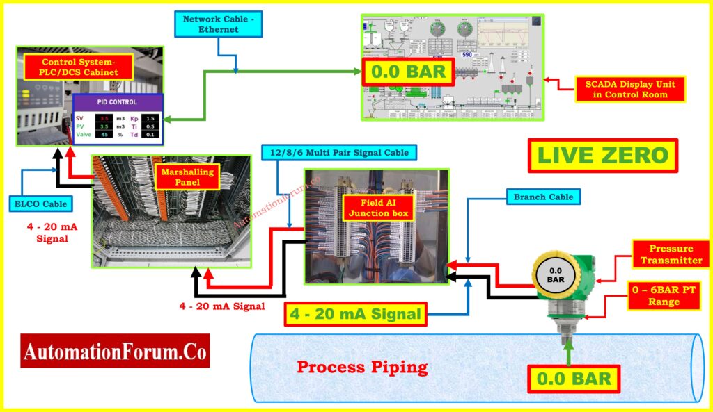
Refer the above figure Figure for a clear field level wiring layout that demonstrates how a live zero 4 to 20 mA loop is wired from the transmitter through junction box and marshalling to the PLC and SCADA, enabling immediate fault detection when the loop opens.
Figure Explanation – Live zero field wiring and loop flow diagram
This diagram illustrates a properly functioning live zero 4 to 20 mA instrumentation loop from field transmitter to control and SCADA. The image shows the pressure transmitter mounted on the process piping, a short branch cable to the field analog input junction box, multi pair signal cable from the junction box back to a marshalling panel or terminal cabinet, ELCO wiring into the PLC or DCS cabinet, and the network connection to the SCADA display. The key message is that at zero process value the transmitter produces a non zero signal value, typically 4 mA, so the control system sees a live healthy loop even when the measured parameter is zero. From an operational perspective this arrangement provides immediate loop health visibility. If the transmitter loses power or the wiring opens the loop current falls to 0 mA and the DCS can immediately flag a bad PV alarm instead of interpreting the reading as a true zero. This wiring chain also supports two wire loop powering, long cable runs and HART diagnostics where available. Use this figure when explaining live zero concept, loop integrity checks and commissioning procedures. Emphasize how marshalling panels and junction boxes are used for neat wiring and isolation and how PLC input modules interpret under range values.
Why 4 to 20 mA Became the Industry Standard
The widespread adoption of 4 to 20 mA is directly linked to eliminating the dead zero problem.
Key Advantages of 4 to 20 mA
- Clear separation between measurement and failure
- Immediate detection of open circuits and power loss
- Strong immunity to electrical noise
- Stable signal transmission over long cable runs
- Compatibility with smart transmitters and diagnostics
For these reasons, 4 to 20 mA remains the preferred analog signal for critical process measurements worldwide.
Learn how to simulate 4–20 mA signals: How to simulate 4-20ma signal with Loop Calibrator ?
Real Process Industry Examples of the Dead Zero Problem
Flow Measurement in Cooling Water Systems
In a cooling water flow loop using 0 to 20 mA, a zero reading may indicate no flow or a failed transmitter. Operators cannot determine the true condition without field verification. With 4 to 20 mA, zero flow still produces 4 mA, while transmitter failure produces 0 mA. This eliminates uncertainty and speeds up decision making.
Level Measurement in Chemical Storage Tanks
A 0 to 10 volt level transmitter showing 0 V may indicate an empty tank or a failed instrument. Assuming the tank is empty when it is actually full can lead to overfilling, chemical spills, and environmental damage. Dead zero signals make voltage based level measurement especially risky in hazardous services.
Pressure Measurement in Process Pipelines
A pressure transmitter using a dead zero signal may show zero pressure during a power failure. Maintenance teams may incorrectly assume the pipeline is safe to open. This example highlights how dead zero signals can create serious safety hazards.
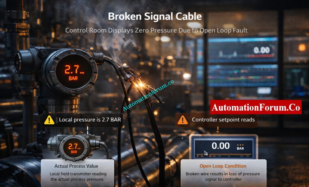
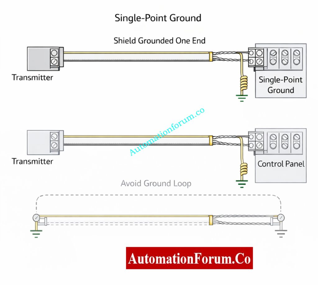
Dead Zero Issues in Voltage Based Analog Signals
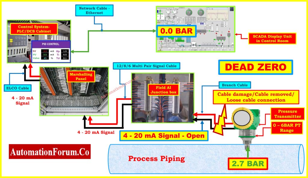
The above figure shows a real dead zero failure where cable damage or a loose connection causes the loop to go open and the DCS to display zero while the field transmitter measures a non zero value.
Figure Explanation – Dead zero scenario showing open loop and false zero reading
Reactor Feed Flow Control Loops
In a reactor feed loop using 0 to 20 mA, a signal drop to zero may cause the controller to fully open the control valve. If the transmitter has failed rather than the flow stopping, this can lead to uncontrolled feed, process upset, or emergency shutdown. Use live zero and safe state logic to avoid this.
Convert 4–20 mA to PLC voltage counts: Calculator for 4-20mA Signal to 1- 5Volt and PLC 16-bit Raw Count Values
Dead Zero Problems in Voltage Based Analog Signals
Voltage based signals are more vulnerable to dead zero issues due to:
- Voltage drop over long cable distances
- Electrical noise and electromagnetic interference
- Grounding and reference problems
- Lack of inherent fault detection
As a result, voltage signals are typically limited to short distance panel wiring or non critical applications and are avoided in harsh industrial environments.
Step by step 4–20 mA loop troubleshooting: How to do troubleshooting of a 4-20mA loop?
Dead Zero During Commissioning, Maintenance and Safety Systems
Commissioning Phase Challenges
During loop checking and commissioning, transmitters are frequently powered on and off. In dead zero systems, it becomes difficult to confirm whether a zero reading is due to testing or an actual process condition.
Maintenance Phase Challenges
When a transmitter is taken out of service, the control system may continue to display a valid zero. Operators may unknowingly operate the plant without a critical measurement, increasing operational risk and downtime.
Pressure gauge versus transmitter which one accurate: Pressure Gauge vs Pressure Transmitter: When Readings Don’t Match, Who Should You Trust?
Role of Dead Zero in Safety Instrumented Systems
The dead zero problem is significantly more important in safety instrumented systems.
- A malfunctioning instrument could look like a safe zero state.
- The logic solver may not be able to find signal loss.
- Necessary safety measures may not be implemented.
Live zero signaling makes sure that safety systems can easily tell the difference between genuine measurements and broken instruments, which helps lower risk in a reliable way.
Test your zero elevation troubleshooting knowledge: Zero Elevation Level Measurement Troubleshooting Quiz for Process Industries (Advanced 25 MCQs with Answers)
Importance of Dead Zero Awareness for Control Room Operators
Operators are usually the first to see readings that are out of the ordinary. If you don’t know about the dead zero problem, you can miss or misread zero values.
Some common misconceptions are:
- Assuming that zero always signifies the process has stopped
- Ignoring zero readings when the power goes out
- Putting off reporting problems with instruments
Teaching operators to investigate unusual zero readings makes response time and plant safety far better.
Safely zero DP transmitter using valve manifolds: How to Safely Zero a DP Transmitter with 3-Way Valve and 5-Way Valve Manifolds
Dead Zero Considerations in Modern Digital Instrumentation
Even in plants using digital communication protocols, analog signals are still commonly used as primary or backup outputs from smart transmitters.
If these analog outputs are configured using dead zero ranges, the benefits of digital diagnostics are reduced. When you use live zero principles, hybrid analog and digital systems will work the same way every time.
Long Term Operational and Cost Impact of Dead Zero Signals
At first, dead zero signals may seem easier or cheaper, but they end up costing more in the long run.
Costs that aren’t obvious include:
- More work to fix problems
- More work needed for maintenance
- Longer periods of downtime
- Higher chance of process problems and accidents
Live zero signaling cuts these costs by making it easier to find faults and make diagnoses more quickly.
Calculate DP zero suppression for level measurement: DP calculator for Zero suppression – open tank level measurement
EPC and Instrumentation Design Perspective on Dead Zero
From an EPC and lifecycle design point of view, dead zero signals add unneeded risk to operations.
The best design practices are:
- Setting all important analog loops to 4 to 20 mA
- Clearly showing the ranges of signals on data sheets and loop diagrams
- Setting up warnings for faulty signals and under range in control systems
- Setting safe control actions to take when a signal fails
These approaches make plants more reliable and easier to maintain.
Situations Where Dead Zero Signals Still Exist in Plants
You might still find dead zero signals in:
- Old installations
- OEM skids in boxes
- Utility systems that don’t cost much
In these situations, constraints must be explicitly stated, and operators must be taught to be careful when they get zero readings.
Refer the below link for Why engineers avoid using 0–20 mA signals
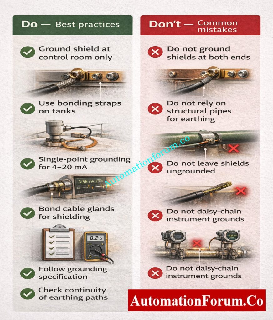
Best Practices to Avoid the Dead Zero Problem
- Always use live zero signals between 4 and 20 mA for process measurements.
- Stay away from voltage-based signals in tough industrial settings.
- Set up alarms for low range and weak signal
- If you have a bad signal, go to safe state or manual mode.
- Teach train operators and maintenance workers how to spot signal failures.
Why Live Zero Signaling Is Essential for Safe and Reliable Plants
The dead zero difficulty in industrial analog signals is a basic problem with instrumentation that still affects process plants all over the world. It shows how a choice about the range of a signal that seems modest can have big effects on safety, control performance, and maintenance efficiency.
Plants may get rid of confusion and make things much more reliable by using 4 to 20 mA live zero signaling, setting up the right diagnostics, and making sure that everyone in engineering and operations knows about them.
In the process industry, a signal that can clearly indicate its own failure is just as important as one that accurately measures the process variable.
FAQ on dead zero problem in analog signal
What is live zero and dead zero?
Dead zero uses a signal that starts at 0, where zero can mean either a real process value or a signal failure.
Live zero starts above zero, typically 4-20 mA.
Here, 4 mA represents zero process value, and any value below 4 mA indicates a fault.
What are some common problems with analog signals?
Analog signals can suffer from noise, cable damage, power loss, and grounding issues.
Voltage drop over long distances and calibration drift are common.
Dead zero signals can hide transmitter or wiring failures.
Why do we use 4-20 mA instead of 0-20 mA current signal?
4-20 mA avoids the dead zero problem.
In 0-20 mA, 0 mA can mean zero process value or signal failure.
With 4-20 mA, any current below 4 mA clearly indicates a fault.
Which is better, 4-20 mA or 0-10 V?

4-20 mA is better for industrial use.
It is immune to noise, works over long distances, and detects open circuits.
0-10 V is more sensitive to noise and voltage drop.
How to convert 4-20 mA to 0-10 V?
A signal converter or signal conditioner is used.
A resistor alone gives only 2-10 V from 4-20 mA.
Active converters provide proper scaling, isolation, and accuracy.
What is the maximum distance for a 0-10 V signal?
Usually between 30 and 100 meters, depending on the quality of the cable and the amount of noise.
As the distance increases, so does the voltage loss and interference.
For longer runs, 4–20 mA is better.
Refer the below link to Calculate Temperature Transmitter 4-20mA Output Using Linear Equation and Percentage Method