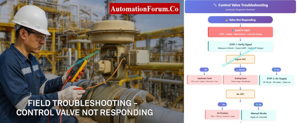
Home Blog Page 17

Field Troubleshooting Guide: Control Valve Not Responding in Process Area

0
Field Troubleshooting Guide: Control Valve Not Responding in Process Area

Reported Issue:  A control valve in the process area does not move or respond to control system commands.

Objective:  To safely and quickly find out if the problem is with the instrument signal, actuator, or valve body, and then fix the valve so that it works properly again without putting plant safety at risk.

Control Valve Troubleshooting Flowchart
⚙️ AUTOMATIONFORUM.CO ⚙️

🔧 Control Valve Troubleshooting

Systematic Diagnostic Flowchart

⚠️ Valve Not Responding
🛡️ SAFETY FIRST
LOTO • Isolate • Depressurize • Lock Out Energy
STEP 1: Verify Signal
Measure 4-20mA • Check HART • Verify I/P Output
Signal OK?
❌ No
Upstream Fault
DCS card • Cables • Terminals • Fuse
⚠️ Wrong
Scaling Issue
Check range • Recalibrate
✅ Yes
STEP 2: Air Supply
20-30 psi • No leaks • Clean air
Air OK?
❌ No
Air Problem
Filter • Tubing • Solenoid • Leaks
✅ Yes
Manual Stroke
Apply air manually
Strokes?
🔄 Hunting
Instability
Feedback • Friction • Tuning
❌ No
STEP 3: Isolate
Disconnect actuator
✅ Yes
Positioner Fault
Calibrate • Check linkage
Actuator Free?
❌ No
Actuator Defect
Diaphragm • Spring • Piston
Repair/Replace
✅ Yes
STEP 4: Valve Body
Test handwheel • Check packing
Moves?
⚠️ After Loosen
Packing Issue
Over-tight • Adjust/Replace
❌ Stuck
Body Failure
Jammed • Bent • Corrosion
Workshop Repair
📋 Post-Maintenance
Stroke test • Calibrate • Check leaks • Document
✅ Return to Service
Start/End
Safety/Critical
Step
Decision
Problem
Success
⚙️ AUTOMATIONFORUM.CO ⚙️
Field Troubleshooting Guide: Control Valve Not Responding in Process Area - Safety First – Isolation and Preparation Steps

To safely and quickly find out if the problem is with the instrument signal, actuator, or valve body, and then fix the valve so that it works properly again without putting plant safety at risk.

Safety is the first and most important thing to do before touching the valve or any of the equipment that is attached to it. Control valves deal with process fluids that may be under high pressure, temperature, or even dangerous circumstances. Accidents can happen if you don’t handle things right.

Next, cut off the valve from the process line. You can achieve this by closing the block valves upstream and downstream or by going around the valve. Before you start any inspection, be sure that the length of pipe is not under pressure and has cooled to a safe working temperature.

Shut off and lock off any electrical, air, or hydraulic sources that are linked to the valve or positioner. Make sure these isolation locations are easy to find.

Warning: Never attempt to troubleshoot, stroke, or force a control valve that is still in service or pressurized. Doing so can cause mechanical damage or result in serious injury.
Troubleshoot Control Valve Passing Issues: How to Troubleshoot a Control Valve Passing Problem after Overhauling: Complete Root Cause Analysis

Field Troubleshooting Guide: Control Valve Not Responding in Process Area

A organized diagnostic sequence makes it easy to find the issue location fast, without having to take things apart or stop working. Let’s go through each step carefully.

Must-Have Control Valve Accessories: Essential Control Valve Accessories for Reliable Process Control

Field Troubleshooting Guide: Control Valve Not Responding in Process Area - Step-by-Step Diagnostic Procedure

Purpose:
Before you touch the valve, make sure that the problem isn’t in the control command chain, which goes from the DCS/PLC to the valve positioner.

Action
Make sure that the electrical or pneumatic signal from the control system is getting to the valve positioner correctly.

How to Do It

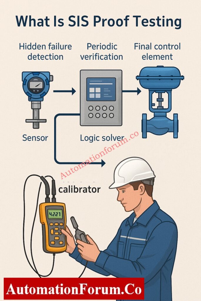
  • Use a calibrated digital multimeter (DMM) or loop calibrator to measure the 4–20 mA analog signal at the input terminals of the valve positioner.
  • Look at the DCS faceplate to see the controller output and compare it to the measured signal.
  • If the valve has a HART positioner, utilize a HART communicator or field communicator to make sure that the setpoint (SP) and feedback (PV) are what you anticipate them to be.
  • Use a pressure gauge to check the output pneumatic signal for I/P (current-to-pressure) converters. It should be a straight line with the input current, such 4 mA = 3 psi and 20 mA = 15 psi.
  • Check the junction box for loose or corroded terminals, broken wires, or water getting in.

Key Control Valve Performance Parameters: Essential Control Valve Performance Parameters

Findings and Interpretation

  • There is no control signal, hence the problem is upstream. A bad DCS output card, an open circuit in the field cable, a shorted loop, a loose terminal, a blown fuse, or wrong marshalling could all be to blame.
  • Signal is there but wrong: Check to see whether the DCS and field device have different signal scales or ranges.
  • Signal is present and correct, so go on to Step 2: Check the health of the air supply and actuator.

Purpose:
The actuator is what makes the valve work. Without clean, stable air, even a flawless signal will not move the valve. 

Action
Make sure the actuator gets enough clean air and that it reacts correctly when signals change.

How to Do It

  • Use a test gauge to check the instrument air pressure at the actuator inlet. For pneumatic actuators, the normal range is 20 to 30 psi (see the nameplate or datasheet).
  • Make sure that the supply pressure stays the same. A sudden dip could mean that there is a problem with the air system.
  • Make sure the air is clean. Oil, grime, or moisture can make things move slowly or stick.
  • Pay particular attention to any air leaks you can hear around tubing, fittings, or diaphragm chambers.
  • Use a hand regulator to slowly change the air pressure at the actuator inlet to determine if the valve stem moves smoothly over its range.
  • For spring-return types, check to see if it goes all the way back when the air is let out.

Benefits of Using Valve Positioners: Why You Should Use Control Valve Positioners?

Findings and Interpretation

  • If there is no air supply or a leak, check for a clogged filter regulator, bent tubing, a broken solenoid, or a torn diaphragm.
  • The actuator or mechanical linkage may be stuck, which means there is enough air yet the valve won’t move. Step 3: Separate the actuator from the valve.
  • Hunting, or unstable actuator movement, can happen because of air starvation, a fault with the positioner feedback, or too much friction in the valve stem.

Tip:
Check the bowl and drain of the air filter regulator all the time. One of the most common reasons for actuator failure in the field is contamination.

Importance of Control Valve Bench Set: Why is Control Valve Actuator Bench Set Important ?

Purpose:
To find out if the actuator is working properly or if the valve’s mechanical parts (trim, stem, plug) are stuck.

Action
To see how they move on their own, disconnect the actuator from the valve mechanically.

How to Do It

  • Make sure there is no energy flow. Turn off all sources of air, electricity, and hydraulics. Follow the plant’s LOTO (Lock-Out/Tag-Out) procedure to tag and lock out the system.
  • Carefully take the actuator stem off of the valve stem or lever coupling.
  • To make sure the actuator moves all the way and smoothly, manually stroke it while delivering controlled air pressure.
  • If the actuator is electric, use the manual handwheel mode or jog the motor in test mode to see it move.
  • Make sure the position feedback linkage isn’t stuck or out of alignment.

Safety Valve Testing and Calibration: Safety Valve Testing and Calibration Procedure

Findings and Interpretation

  • The actuator travels freely when it’s not attached. The actuator and positioner are both fine. The problem is with the valve body. Go on to Step 4.
  • The actuator is broken if it doesn’t move or just moves part of the way. Some such reasons are:
    • Ruptured diaphragm or piston seal leakage
    • Broken return spring in spring-return actuators
    • Corroded or rusted piston rod
    • Sticking due to internal contamination or water ingress

After maintenance, fix or replace the actuator and re-calibrate the positioner.

Best Practice:
While not connected, use a controlled input signal to do a bench stroke test on the actuator to make sure it works properly across the whole range.

Calibrate Your Control Valve Positioner: Calibration Procedure of Control Valve Positioner

Purpose:
If the signal and actuator are working, the valve body probably has mechanical problems.

Action
Check for internal blockages, stuck stems, or friction caused by packing.

How to Do It

  • After making sure that the actuator works, reconnect it.
  • Try to use the valve’s handwheel or override mechanism to manipulate it by hand.
  • Check to see if the valve stem moves smoothly in a straight line or in a circle, depending on how it was made.
  • To see if too much tightening is producing stem friction, slightly loosen the gland packing nuts.
  • Check for leaks or buildup of product around the stem region, since this can be a sign of internal sticking.
  • If you can, check the valve position feedback (via a position transmitter or HART PV) while sending small step signals.
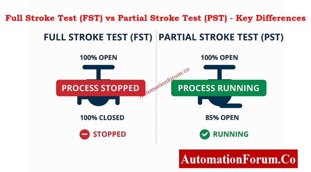
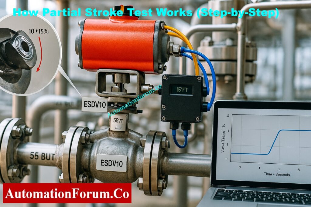
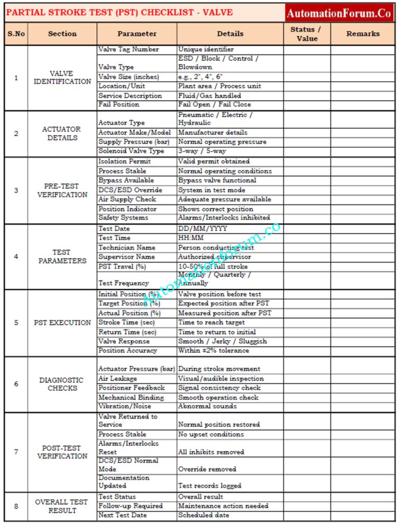
  • For important valves, do a partial stroke test (PST) to make that the travel is correct without completely stopping the flow of the process.

Findings and Interpretation

  • Valve still won’t move: either something is blocking it or it broke. Some possible causes are:
    • Plug or disc jammed due to process debris
    • Bent stem or damaged guide bushing
    • Corrosion or scaling inside the trim
    • Seat-ring or cage galling

You need to take the valve out and bring it to the shop so that it may be taken apart, cleaned, and checked.

Step-by-Step Control Valve Calibration: Control Valve Calibration Procedure

Additional Recommendations:

  • Use the positioner’s feedback potentiometer or travel sensor to always check the valve travel calibration.
  • Use a diagnostic tool (like Fisher DVC or SAMSON TROVIS) to do a stroke test and signature analysis after maintenance to make sure everything is working properly before putting it back into service.
  • Write down all of your findings in the valve maintenance journal, including signal readings, pressures, and any problems you see for future reference.

Fix Valve Hunting from Positioner Issues: Control Valve Hunting due to Valve Positioner: Troubleshooting

After being taken apart in a safe, controlled setting, a number of mechanical problems can be found to be the main causes:

Corrosion of Internal Components:
Stem pitting, plug seizure, or actuator shaft binding can happen when process fluids are corrosive or the wrong materials are used.

Solid Buildup or Coking: In procedures that use hydrocarbons or polymers, residues can build up between the plug and seat, stopping movement.

Mechanical Damage: If the stems are bent, the seats are eroded, or the metal-to-metal welding is bad, the valve won’t move.

Worn Packing or Bearings: If the packing gland gets too dirty or worn out, it might make the stem stick in the middle of a stroke.

Improper Assembly or Misalignment: If the actuator linkage is not put together correctly or the positioner is not calibrated correctly, it can cause mechanical interference.

Motorized Control Valve Calibration Guide: Calibration Procedure for Motorized Control Valve
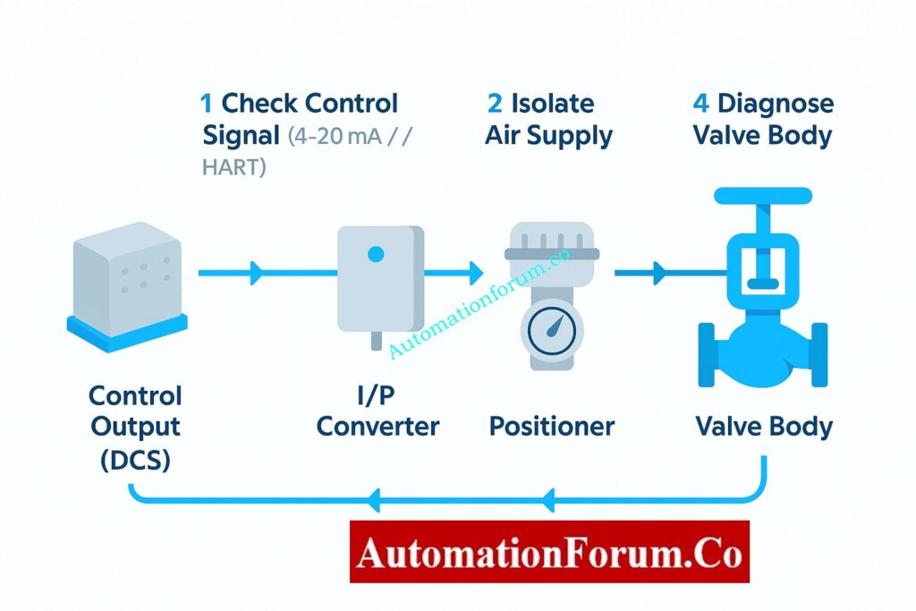
Control valves are one part of a bigger system of automation. A valve that doesn’t respond doesn’t automatically signify that the mechanism has broken; it could be a problem somewhere in the signal chain.

Let’s take a quick look at how these parts work together:

  1. Controller Output (DCS/PLC):
    Makes a 4–20 mA command signal that is based on how much the process needs.
  2. I/P Converter or Positioner:
    Turns the electrical signal into air pressure (3–15 psi).
  3. Actuator:
    Changes air pressure into mechanical motion.
  4. Valve Body:
    Changes the flow of fluid based on the movement of the stem or stopper.

If there is a break in this chain, whether it is electrical, pneumatic, or mechanical, the valve may stop working.

Troubleshoot Control Valve Noise Problems: Troubleshooting Control Valve Noise and Cavitation

Keep the following best practices in mind to make the troubleshooting process faster and easier to repeat:

  1. Document Everything:
    Before you start, write down the valve tag number, the readings from the control signal, the pressures in the air supply, and any feedback from the positioners. This documentation allows you compare how things worked before and after maintenance.
  2. Check Linkages and Mountings:
    If the linkage arms between the positioner and actuator are loose or not lined up correctly, they might give erroneous position feedback and cause the actuator to move in strange ways. Make sure they are tight or in the right place.
  3. Inspect Feedback Mechanisms:
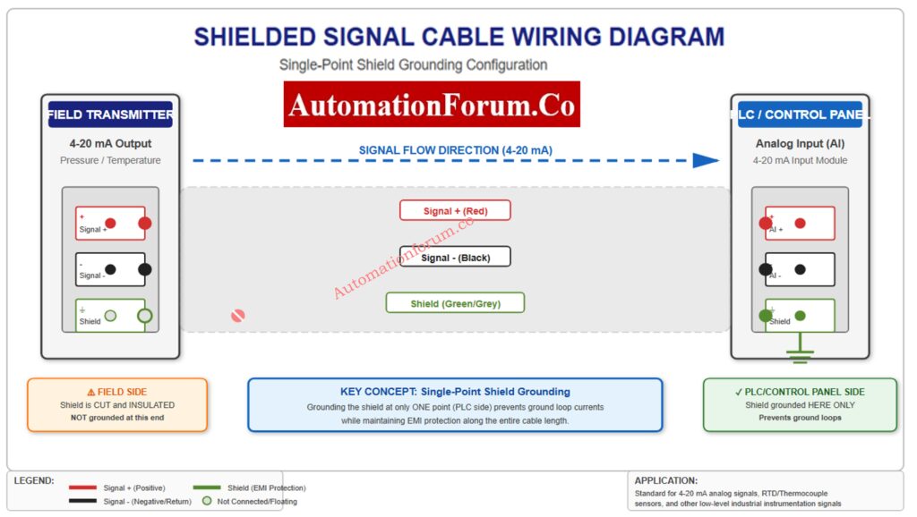
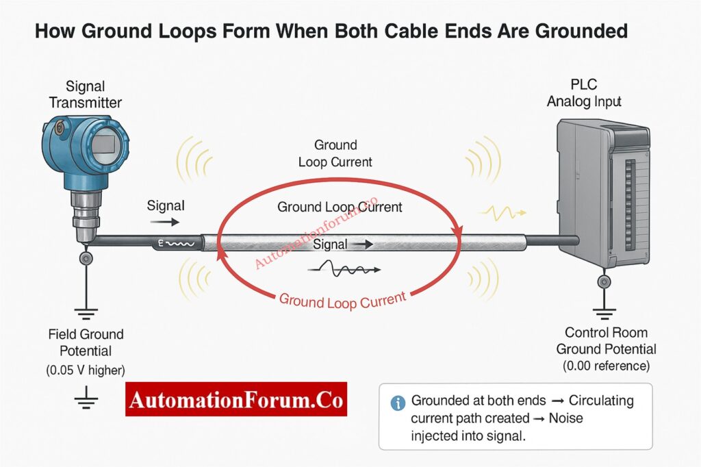
    Check to see if the feedback potentiometers or sensors are working properly for smart positioners. Bad sensors can make the valve look “dead” even when it is working fine.
  4. Verify Grounding and Shielding:
    Electrical noise can make it hard for signals to get through, especially in analog loops. Make sure that cable shields are only grounded at one end, which is usually the side with the control panel.
  5. Perform Full-Stroke and Partial-Stroke Tests:
    After fixing the problem, do both full-stroke (0–100%) and partial-stroke tests to make that the travel is smooth, linear, and repeatable.
  6. Check Packing Leakage:
    After re-pressurizing the valve, check for leaks around the stem packing using a soap solution or leak detection spray.
  7. Always Return to Safe Condition:
    When the tests are done, put the valve back in its usual functioning mode and let the control room know before taking away the bypass conditions.

If all the basic checks pass but the valve still doesn’t work, you might want to look into these more advanced diagnostic options:

  • Positioner Calibration Errors: New smart positioners (such Fisher, Siemens, ABB, and Samson) might lose their calibration if the power goes out or the settings are wrong. Use the manufacturer’s handheld communicator or software tool to tune and calibrate again.
  • Sticky Valve: If a valve doesn’t move much over time, the seal can adhere to it. This doesn’t happen as often when you do regular partial-stroke testing.
  • Actuator Spring Fatigue: In designs using spring returns, springs that are too weak may not produce enough counterforce, which can cause movement to slow down or stop.
  • Air Locking or Water Condensation: If moisture becomes stuck in pneumatic lines, it can freeze or stop the flow of pressure. It is very important to drain filters and traps on a regular basis.
  • Electrical noise and signal distortion: If the positioner gets signals that change, check the grounding and shield termination. If shields aren’t grounded properly, they can make loops that cause noise.

Common Causes of Valve Hunting: Main Causes of Control Valve Hunting

Most of the time, control valve failures don’t happen all at once; they happen over time. A well-planned preventive maintenance (PM) schedule can cut down on unscheduled shutdowns by a lot.

  • Plan regular valve stroke checks during planned outages.
  • Check and clean air filters and regulators from time to time.
  • At the prescribed times, change the actuator seals and diaphragms.
  • To keep moisture and dust out of field junction boxes, make sure they are properly protected from the outdoors.
  • For every change, make sure you update the as-built drawings and loop diagrams.

Control Valve Leakage Testing Standards: Control Valve Leakage Testing, Types, and Calculation Standards

  • Digital multimeter (for checking 4–20 mA signals)
  • Pressure gauge with a range of 0 to 30 psi
  • HART device or handheld communicator (for smart positioner diagnostics)
  • Air supply source and tubing that can be moved
  • Wrenches and hex keys that can be changed
  • Spray for finding leaks
  • Safety gear includes gloves, goggles, a face shield, and hearing protection.

Don’t assume that the valve is broken right away. Before doing any mechanical work, always check the signals and power.

Write down and tell the control room and maintenance records about whatever you uncover.

Use preventative measures to cut down on the number of times valves don’t work in the future.

Control Valve Troubleshooting Checklist (Excel Download)

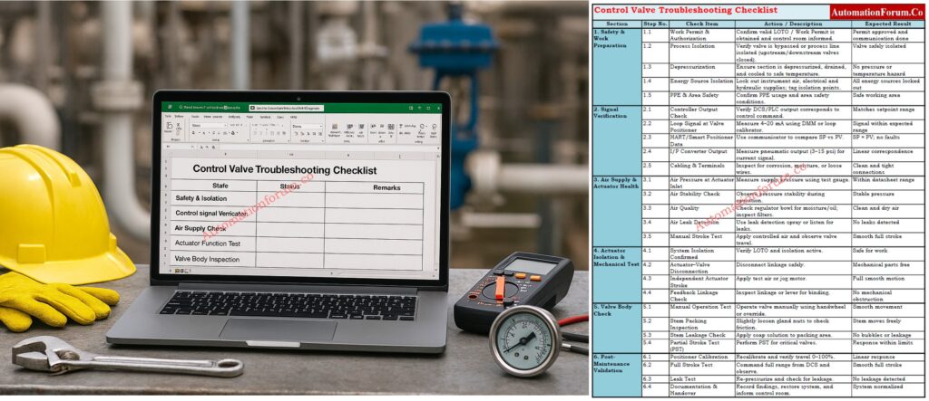
A useful checklist for maintenance engineers to use in the field to help them figure out what’s wrong with control valves. It includes procedures for safety, signal verification, actuator testing, valve inspection, and post-maintenance validation. Use the link below to download

Some common problems are not getting enough air, becoming stuck because of dirt or corrosion, worn packing, and a positioner or actuator that doesn’t work right. These faults often make the valve move in strange ways or not respond to control signals.

If there is no control signal, the air pressure is too low, the actuator is broken, or anything is blocking the valve trim, it might not open. Before checking the mechanics, you should first check the air supply and signal chain.

Make sure the control signal, air supply, actuator movement, and valve stem work. Always check the positioner feedback and recalibrate the valve after repairs to make sure it works properly in automated mode.

Flow control is lost, which can lead to process instability, pressure problems, or moving to the fail-safe position. This can set off alarms or make the system shut down on its own, depending on the process.

The flow or pressure of the process becomes unstable, which can cause production loss, safety issues, or damage to equipment. To avoid more problems with the process, troubleshooting and isolation must be done right away.

Look at the actuator nameplate or watch the valve move when the air is lost. “Air-to-open” indicates “fail-close,” and “air-to-close” means “fail-open.” This information helps make sure that the right fail-safe action is taken in an emergency.

Why the Cable Shield is Grounded Only at the PLC or Control Panel Side

0
“Instrumentation cable with shield grounded at PLC side”

One of the most important parts of instrumentation and control engineering in process industries is making sure that signals are sent and received accurately and consistently. Cable shielding and grounding are two of the most important ways to ensure signal integrity.

When working with low-level analog signals like 4–20 mA current loops, RTDs (Resistance Temperature Detectors), thermocouples, or transducer outputs, even a little bit of electrical noise can make readings wrong, processes unstable, or controls stop working. That’s why it’s so crucial for every instrumentation engineer and technician to know why the cable shield is only grounded on the PLC or control panel side.

This article goes into great detail on the idea, logic, and best practices underlying this important discipline, which helps professionals in the instrumentation and control industry keep signals reliable and clear in industrial environments.

Learn How Instrument Cable Shielding Protects Your Signals: What is instrument cable shielding?

“Single-end grounding prevents ground loops in PLC signals”

Cable shielding is a protective conductive covering that goes around the signal conductors inside an instrumentation cable. It is usually formed of aluminum foil, braided copper, or metallized tape.

The main job of this shield is to keep outside electromagnetic interference (EMI) and radio frequency interference (RFI) from getting to the internal wires. Motors, variable frequency drives (VFDs), relays, solenoids, high-voltage cables, and switching devices that are used in process plants often make these undesired signals.

The shield works as a barrier and a channel for noise currents when it is properly mounted and grounded. This keeps them from affecting the measurement or control signals inside.

But engineers and technicians sometimes ask, 

“If the shield is supposed to protect the signal, why not ground it at both ends for better continuity?”

To address it, we need to first talk about a very important issue: ground loops.
Top Tips to Avoid Instrumentation Cable Tray Installation Errors: Avoiding Mistakes in Instrumentation Cable Tray Installation: A Guide for EPC Projects

The ground potential at different places in an electrical system may not be the same.

The ground potential at the field instrument, such a transmitter positioned near a process vessel, could be a little different from the ground potential at the PLC or DCS control room, for example. This variation in potential, even if it’s minor, is important when it comes to sensitive analog signals.

When both ends of a cable shield are grounded (at the field instrument and the control panel), an electrical channel is formed between two ground points with different potentials. This makes a current flow in a circle, which is often called a ground loop.

  • The difference in ground potential makes a current flow through the shield.
  • This circulating current creates undesired voltage in the signal wires through electromagnetic coupling.
  • The noise that is caused by the signal might make instruments and controllers give incorrect readings, drift, or distort the signal.
  • In extreme instances, the control system may get the signal wrong, which could cause the wrong control actions or make the system unstable.

For example, a few millivolts of noise in a 4–20 mA loop can change the current level sufficiently to have the PLC read the wrong process value.

To break this loop and stop the current from flowing, the industry norm is to ground the cable shield at only one end, usually the control panel or PLC side.
Step-by-Step Method Statement for Accurate Cable Termination: Method Statement for Instrumentation Cable Termination

“Shielded cable installation for 4–20 mA transmitter to PLC”

For instrumentation and control systems, it’s important to keep all sensitive signals on the same reference ground. By just grounding the cable shield on the PLC or control room side, you make sure that all signals have the same reference point, which reduces noise and voltage differences.

  • The ground for the control room or PLC panel is usually set up with the right earthing networks, filters, and isolation methods. 
  • The ground potential in the control room is more steady and free of noise than it is in the field.
  • Metal structures, pipelines, or process containers are typically used to hold field instrumentation. These structures can have stray currents or changes in ground potential because of neighboring electrical systems or lightning protection grids.

The signal cable’s shield is connected to a clean, stable ground by keeping the instrument end floating (not grounded) and only grounding at the control panel side. This protects the control electronics from noise caused by the field.

This method makes it easy for undesired interference to get through without letting stray currents back into the signal loop.
Complete ATEX Intrinsically Safe Cable Checklist for EPC Projects: Intrinsically Safe Cables for ATEX Zones – Complete Checklist for EPC Engineers

Controlling Electromagnetic Interference (EMI) with Cable Shielding

Another significant reason to only ground the shield on the side of the control panel is to control the passage of noise current.

In factories, electromagnetic interference (EMI) and radio frequency interference (RFI) are omnipresent. They come from motors, contactors, high-current cables, power converters, welding machines, and more. These interferences cause the shield to have voltage.

When the shield is grounded on one side (the control side), it gives the noise a low-impedance path to ground.

This means that the noise current moves toward the grounded end and is safely dissipated, instead of going into the transmitter or sensor’s sensitive analog circuit. 

If the field side were likewise grounded, noise could go both ways, which may cause interference by getting into the transmitter’s circuitry or generating loops.

So, single-end grounding successfully moves noise away from important parts and into a well-designed grounding network where it may be securely neutralized.
IS vs Non-IS Cables: Key Differences Every Engineer Must Know: Difference Between Intrinsically Safe (IS) and Non-IS Cables

To better understand how this rule works, let’s look at a few real-world examples:

A twisted shielded wire connects a pressure transmitter to a PLC analog input card and sends a 4-20 mA signal.

  • PLC side: The shield on the PLC side is connected to the shield terminal of the analog input module, which is coupled to the system ground inside the module.
  • Transmitter side: On the transmitter side, the shield is trimmed short and insulated so it doesn’t touch the housing of the transmitter.

This configuration makes sure that any electromagnetic noise that gets on the cable shield goes to the PLC ground, which keeps the signal strong.

RTD cables carry signals with very low voltages, usually in millivolts. These are quite likely to pick up noise.
Only grounding the shield on the instrument panel side helps keep the temperature reading steady and correct, even when there is electrical noise in the field.

Thermocouples are considerably more sensitive since they employ millivolt variations between different metals to send signals.

Single-point grounding prevents ground loops and false voltage offsets that could lead temperature measurements to be off by several degrees in this situation.
Neutral, Earth, Ground Explained: What Every Engineer Should Know: Difference between Neutral, Earth and Ground

The signal frequencies are substantially higher in communication lines like Ethernet, Profibus, or RS-485. The shielding not only blocks noise at certain frequencies, but it also helps the cable’s characteristic impedance.

In these situations, both ends may be grounded, but only if: 

  • Proper isolation barriers or common-mode filters are used.
  • The grounding system is equipotential, which means that there is very little change in potential between the two ends.
  • The system meets EMC (Electromagnetic Compatibility) design requirements and follows the manufacturer’s instructions.

Some plants use ground equalization conductors (GECs) that keep the same ground potential between control rooms and distant panels.

If they are checked and tested, these kinds of installations can safely support grounding on both ends.

Best Practices for Grounding Instrumentation Cable Shields

Engineers should follow these best practices in the industry to make sure that shielding and grounding work well in instrumentation cabling:

  1. Always connect the shield to the control panel side, which is usually at the analog input card or a separate shield bar that is connected to the system ground.
  2. Leave the field end disconnected and cut and insulate the shield wire to keep it from touching anything by accident.
  3. For all low-level analog signals, like 4–20 mA, RTD, and thermocouple, use twisted pair shielded cables.
  4. To reduce EMI pickup, run signal cables apart from power and high-voltage cables.
  5. Don’t use more than one grounding point unless it was designed that way with isolation.
  6. To avoid making mistakes, make sure the labels on shields in junction boxes and marshalling panels are easy to read.
  7. Keep the ground connections clean. Corrosion or loose terminations might make the shield work less well.
  8. When installing in a dangerous environment, make sure to follow the manufacturer’s and IEC/ISA’s grounding instructions.
  9. During maintenance or troubleshooting, check the shield’s continuity and insulation on a frequent basis.

Accurate Cable Tray Size Calculation Guide for Engineers: Cable Tray Size Calculation for Project Engineers

Even technicians who have been doing this for a long time make mistakes during grounding that impair the quality of the signal. Stay away from these typical mistakes:

  • Grounding both ends of the shield by accident (this happens a lot when the instrument body is made of metal and is grounded through mounting).
  • Connecting shields to signal return or negative lines might lead to mistakes in measurements.
  • Leaving shields floating at both ends, which makes them ineffective.
  • Combining signal and power grounds, which adds noise to control circuits.
  • Incorrect terminations or broken shielding while stripping or installing cables.

One improper connection might cause noise problems that are very hard to figure out later, therefore it’s very important to pay close attention to every little thing during installation.
Proven Techniques to Ground Instrumentation Systems and Minimize Noise: How to properly ground an Instrumentation System to reduce noise?

When using smart transmitters or digital protocols like HART communication over 4–20 mA loops, grounding should follow the manufacturer’s EMC and safety recommendations in some circumstances.

Analog signals work best when grounded at one point, although some hybrid or smart systems may feature built-in isolation or capacitive coupling that lets both ends be grounded securely. Before making a decision, always read the handbook for the equipment.

Proper shielding and grounding are the most important things for making sure that signals are sent reliably in instrumentation and control systems. Only grounding the cable shield on the PLC or control panel side makes sure that all noise currents get securely to a stable ground, gets rid of ground loops, and keeps a single reference point.

By adhering to this practice, engineers can:

  • noise-free signal transmission by following this method.
  • Stop mistakes in measurements and keep control from going wrong.
  • Make both field instruments and control systems last longer and work better.

In today’s complicated industrial settings, where electrical noise and interference are always present, an experienced instrumentation technician knows how to use the right shielding procedures.

No matter if you’re setting up a new system, fixing signal problems, or checking installations, always keep in mind that one end should be grounded and the other should be floating. That’s the most important rule for grounding a shield.

Earth Fault vs Ground Fault: Clear Differences Explained: Difference between Earth Fault and Ground Fault

“Instrumentation cable with shield grounded at PLC side”

 Yes. To securely redirect electromagnetic interference (EMI) and keep the signal strong, cable shields must be grounded. The shield can’t block outside sounds well if it isn’t grounded.

It depends on the type of signal and how it was installed:

  • For low-frequency analog or instrumentation signals, ground the shield at one end (typically the control panel or PLC side) to prevent ground loops.
  • Grounding both ends of long or high-frequency cables may help protect against noise.

Attach the shield to a grounding point with low resistance that is close to the control panel or chassis entry. Make sure the grounding wire is short and sturdy. Make sure that the shield runs the whole length of the wire and that there aren’t more than one ground point for low-level signals to avoid interference.

Grounding correctly keeps people safe, signals stable, and systems reliable. It keeps workers safe from electric shock, stops PLC gear from breaking, and cuts down on electrical noise that can generate false signals or system problems.

If you don’t ground your electrical system, metal parts can get energized, which can be dangerous. It can also make electrical noise worse, which might cause communication problems, equipment failures, or wrong process indications.

The plant’s main earth ground connects to the PLC enclosure and power supply. This earth is connected to the internal signal reference (0 V) to keep a steady reference for input/output modules and make sure that shielding and noise reduction work well.

Complete Guide: Cable & Wiring Inspection Procedure for Projects: Instrumentation Cable and Wiring Inspection Procedure: Essential  checklist for Project Engineers

What is Partial Stroke Test (PST)? A Complete Guide for Shutdown and Control Valves

0
What is Partial Stroke Test (PST)? A Complete Guide for Shutdown and Control Valves

Safety and reliability are the most important things in modern manufacturing processes. Shutdown and control valves are very important for automated processes because they keep people, equipment, and the environment safe from dangerous conditions. These valves need to work perfectly when needed, but they typically sit unused for long periods of time.

Engineers utilize a method called the Partial Stroke Test (PST) to make sure that their machines work without stopping production. This simple but effective strategy makes sure that important valves can move when they need to, giving you confidence of mind that the system will work properly if it needs to shut down.

In process sectors including oil and gas, refineries, petrochemicals, and power plants, valves often have to work in very severe situations, like high pressure, temperature, and corrosive environments. Many of these valves are emergency or block valves that stay in one position (completely open or closed) for months or even years.

These kinds of valves may get:

  • Stem friction or sticking
  • Internal corrosion
  • Air supply leakage in pneumatic actuators
  • Mechanical binding or seal hardening

These problems can stop the valve from moving when a shutdown command is sent, which can lead to hazardous circumstances or expensive downtime.

Operators used to depend on Full Stroke Tests (FST) to fully open and close the valve during planned plant shutdowns. But this meant pausing production, which took a lot of time as well as resources.

The Partial Stroke Test is a better option because it lets you check valve movement without stopping work.

Control Valve Passing Issue? Troubleshoot Now: How to Troubleshoot a Control Valve Passing Problem after Overhauling: Complete Root Cause Analysis

A Partial Stroke Test (PST) is a way to move a valve’s actuator and stem only 10% to 20% of its total stroke to see if the valve responds to control signals and travels freely.

A PST checks the basic health of the mechanics and actuators while keeping the process going normally. This is different from a Full Stroke Test, which needs a full open/close action.

During a PST, parameters such as:

  • Valve position
  • Response time
  • Actuator pressure
  • Load factor

are monitored and recorded. This information helps maintenance personnel find possible mechanical or pneumatic problems early on, which keeps the machines from shutting down unexpectedly.

Prepare Perfect Control Valve Datasheets: How to Prepare Control Valve Datasheets: A Step-by-Step Procedure for EPC Instrumentation Engineers

Full Stroke Test (FST) vs Partial Stroke Test (PST) - Key Differences
AspectFull Stroke Test (FST)Partial Stroke Test (PST)
Extent of Movement100% valve travel (fully open/close)Typically 10–20% movement
Process InterruptionRequires shutdown or bypassNo process interruption
Failure DetectionDetects all possible faultsDetects about 70% of common faults
Testing FrequencyDone during major maintenance turnaroundsCan be done monthly or quarterly
Cost and EffortHigh due to downtimeLow – performed online
PurposeFull integrity verificationRoutine health check
How Partial Stroke Testing Works  Step-by-Step

Partial Stroke Testing (PST) uses smart valve positioners with built-in diagnostics that accurately regulate and measure how the valve moves. The Dynamic Ramp Method is the most common way to make modern safety systems work. It makes sure that motion is smooth, data is collected accurately, and the process is disturbed as little as possible.

The operator can start the PST by hand using the control system interface, or it can start automatically depending on a timetable set up in the logic solver or asset management system. This flexibility lets you check things regularly without having to stop the workflow or isolate repairs.

When the intelligent valve positioner is triggered, it sends a small, controlled ramp signal to the actuator, telling the valve to move a short distance, usually 10–15% of its total stroke. This small range of motion makes sure that the valve doesn’t stop the flow of the process or put the plant’s safety at risk.

While the ramp is moving, the system uses a non-contact Hall Effect sensor or a similar feedback mechanism to keep an eye on the valve’s real location. At the same time, the pressure of the pneumatic actuator is measured to see how well and reliably the valve responds to control signals.

When the valve reaches the set partial stroke limit, the positioner automatically tells it to go back to the completely open or closed position, depending on how it normally works. To avoid pressure shocks or process disturbances, the changeover is done smoothly.

The smart positioner keeps track of things like position, time, actuator pressure, and travel deviation over the whole test cycle. This information is used to make a valve signature graph, which shows how well the valve works under test settings.

You can find problems early, such slow reaction, too much friction, stiction (static friction), hysteresis, or too much actuator pressure. These problems usually mean that something is worn out, partially blocked, or leaking air, which gives maintenance workers time to fix them before a full-stroke demand or process halt happens.

PST’s automated, non-intrusive technology allows for continuous checking of the health and safety performance of valves without stopping the process. This makes sure that IEC 61511 is followed and that proof tests for Emergency Shutdown (ESD) valves are more thorough.

The extent of valve travel during Partial Stroke Testing (PST) is intentionally restricted to ensure that normal process conditions remain stable and that there is no interruption or upset to production. The goal is to test the mechanical integrity and responsiveness of the valve and actuator without allowing the valve to reach a position that could alter process flow or pressure significantly.

  • 10–15% Stroke: This range is usually used for conventional on-off process valves that control liquids, gases, or steam in non-critical loops. It moves enough to check the actuator torque, stem friction, and response time without changing the flow rate of the process.
  • 5–10% Stroke: A lower stroke range is chosen for systems that deal with high-pressure applications, critical utilities, or very sensitive process loops. This lowers the chance of pressure spikes, flow problems, or stress on equipment, especially when even a small movement of the valve can change the balance of the operation.

Must-Have Control Valve Accessories: Essential Control Valve Accessories for Reliable Process Control

There are a number of engineering factors that go into finding the best partial stroke percentage:

  • Process Type:
    Continuous processes, like refineries or chemical plants, usually employ smaller strokes to keep the operation stable. Batch operations, on the other hand, may tolerate slightly bigger movement windows during non-critical phases.
  • Valve Size and Actuator Power:
    To get quantifiable movement, bigger valves with higher torque actuators may need smaller relative stroke percentages. This is because too much travel could cause undesired flow changes.
  • Acceptable Process Fluctuation:
    The process’s ability to handle small changes in flow or pressure is very important. In systems that are very carefully controlled, a movement of about 5% may be the most that can happen. In systems that are less sensitive, a movement of up to 15% is possible.
  • Valve Design and Service Conditions:
    The right stroke limit for reliable testing also depends on the type of valve (ball, butterfly, or globe), the service medium (liquid, gas, or slurry), and the temperature and pressure at which it works.

A small movement of the stem, even only a few millimeters, can show that the valve works, the seal is good, and the actuator responds. This makes sure that the valve will work as predicted during a full-stroke demand in an emergency, without putting the plant at risk during routine checks.

Find Control Valve Stroke Length: Control Valve Stroke Length Calculator

Depending on the extent of automation in the plant and the technology that is available, there are many ways to set up a PST

TypeDescriptionApplication
Mechanical PSTManual device with a mechanical limiter or handle to restrict movementLow-cost installations
Electro-Pneumatic PSTUses solenoid valves and limit switches for partial actuationSemi-automated systems
Digital PST (Intelligent Positioner)Fully automated test with feedback and diagnosticsMost modern plants
Remote PSTPerformed remotely via DCS or control systemOffshore and hazardous zones

Partial Stroke Testing makes safety, dependability, and maintenance more effective in measurable ways.

  • Detects Stuck Valves: Finds mechanical blockages before they cause a failure.
  • Ensures Valve Movement: Checks if the actuator works and the signal is clear.
  • Lessens Failure Probability: Finds up to 70% of common valve problems early on.
  • Keeps the process safe: Checks to see if the valve is ready without shutting it down.
  • Predictive Maintenance: Looks at test data to figure out how valves are likely to wear down over time.
  • Optimized Shutdown Planning: Lengthens the time between full maintenance turnarounds.
  • Spare Parts Management: Lets you order important spare parts on schedule.
  • Reduced Labor: Automated testing cuts down on the requirement for manual examination.
  • No Process Downtime: PST can be done while the process is running normally..
  • Lower Testing Cost: No need for extra bypass or isolation systems.
  • Better availability of equipment: keeps the plant running smoothly.

In brief, PST guarantees that valves will work with the least amount of money spent and the most effort spent.

Equal Percentage Flow Calculator: Equal Percentage Control Valve Flow Calculator

Smart positioners today record useful diagnostic data during each PST. Some common parameters are:

ParameterDescriptionPurpose
Valve PositionActual valve travel vs. commanded movementChecks stem response
Actuator PressureAir pressure needed to move the valveDetects air leaks or sticking
Response TimeTime taken to complete partial movementIndicates sluggishness or blockage
Load FactorRatio of actuator pressure to stem movementDetects friction or internal wear

Engineers use this information to make valve health reports and compare past results to see how performance has changed over time.

Control Valve ITP Download Here: Inspection and Test Plan (ITP) for Control Valves

PST can be used with many different control and shutdown systems, but there are a number of international standards that spell out what is expected of functional valve testing.

  • IEC 61511: Sets the standards for test intervals, proof tests, and diagnostic coverage for process control applications.
  • ANSI/ISA 84.00.01: This is a North American standard that is in line with IEC 61511 and gives advice on how to test and validate automation.

Understand Split-Range Valve Control: Understanding Control Valve Functions in Complementary, Exclusive and Progressive Split-Range Control Systems

Interpreting PST Results

Engineers look at the test curves after each Partial Stroke Test to figure out how the valve works.

A healthy valve signature has a smooth ramp-up and return curve, steady actuator pressure, and timing that can be repeated.

Abnormal signatures may mean:

  • Delayed reaction (there may be a problem with the actuator)
  • Pressure that doesn’t follow a regular pattern (air leaks or mechanical friction)
  • Too much load factor (sticking or rusting)
  • No movement (the valve is stuck or the signal is broken)

By looking at these results over time, maintenance staff can figure out when a valve needs to be fixed or replaced.

Partial Stroke Testing has some pros and downsides that should be thought about before it is put into use.

If set up wrong, a PST may make the valve close all the way, which would stop production by accident.

Solution: The positioner should have position limiters and soft-stop control logic.

In operations with very tight control margins, even a 5% valve movement can change the flow or pressure.

Solution: Do PST when the system is stable or when the load is low.

PST can’t find all kinds of failures, such leaks in the seat or problems with the whole stroke.

Solution: Use PST together with full stroke testing every now and then during significant shutdowns.

Some operators are afraid about unscheduled journeys and don’t want to employ PST.

Use certified smart positioners that include fail-safe testing modes and teach the people who work in the control room.

How often you do a Partial Stroke Test depends on:

  • Valve criticality
  • Failure history
  • Process importance

Typical guidelines suggest:

  • Monthly testing for high-risk valves
  • Quarterly or semi-annual testing for moderate service
  • Annual testing for less critical valves

To keep track of everything, every PST should have a date, valve ID, operator name, test result, and comments written down.

Think about a refinery feed isolation valve that stays open while the plant is running normally.
The plant’s control system sets up a PST every month:

  1. The valve positioner moves it 15% toward closed.
  2. The movement time and actuator pressure are recorded.
  3. The valve returns to open position automatically.
  4. The diagnostic software flags a slight delay in closing movement compared to the previous test.
  5. Maintenance is scheduled to inspect the actuator, preventing future failure.

This straightforward example demonstrates how PST guarantees valve dependability while preventing process interruption.

Future Trends in Partial Stroke Testing

As digital instruments get better, PST systems are getting smarter and more integrated.

  • wireless PST monitoring for installations that are far away.
  • Cloud-based diagnostic tools and maintenance dashboards that are all in one place.
  • AI and predictive analytics for figuring out problems before they happen.
  • Integration with Asset Management Systems (AMS) for full tracking of equipment health.

These improvements turn PST from a simple test of valve movement into a powerful tool for predicting maintenance and reliability.

The Partial Stroke Test (PST) is a very useful and cost-effective approach to make sure that important valves in process plants are ready to work. Engineers can see early indicators of mechanical failure, actuator malfunction, or signal problems by moving the valve a little bit without stopping the process.

When applied consistently, PST offers:

  • More safety and dependability
  • Less time spent on repairs and downtime
  • Better performance and availability of equipment

Partial Stroke Testing is still one of the most useful techniques for making sure that valves work properly in modern industrial automation, whether they are employed in shutdown systems, control valves, or isolation applications.

Top Control Valve Excel Tools: Top Essential Control Valve Calculators and Excel Tools for Instrumentation Engineers

Partial Stroke Test (PST) Checklist - Excel Template

The Partial Stroke Test (PST) Checklist makes sure that important on-off or emergency shutdown valves are checked for performance on a regular basis without stopping the process. This list gives you a way to write down important information about valves, test setups, observations, and follow-up activities in an organized way. It helps maintenance and reliability teams follow IEC 61511 / ISA S84 safety rules and makes sure that all field devices have the same documentation.

A Partial Stroke Test (PST) pushes a valve 5–20% of the way to assess how the actuator responds and how the valve moves without stopping the procedure.

A PST is a test that checks the safety and control valves while the plant is running normally to see if they are sticking, causing friction, or having actuator problems.

Test for Partial Stroke.

It makes guarantee that on-off valves (ESD or block valves) can move safely during an emergency shutdown.

  • Verify valve movement
  • Detect mechanical or actuator issues
  • Reduce downtime
  • Improve safety proof test coverage
  • High-risk valves: Monthly
  • Moderate: Quarterly or semi-annual
  • Low-critical: Annually

No. PST finds about 70% of problems, however FST is needed for comprehensive integrity tests.

  • ESD valves
  • Block/isolation valves
  • On-off and control valves with actuators
  • Functional safety according to IEC 61508
  • IEC 61511: test intervals and proof testing for SIS
  • ANSI/ISA 84.00.01 is a set of rules for North American SIS.

Testing and Repair Deferral – IEC Guidelines, Procedure, and Best Practices

0
Testing and Repair Deferral - IEC Guidelines, Procedure, and Best Practices Introduction to SIS Testing and Repair Deferral Safety Instrumented Systems (SIS) are very important in industrial automation because they keep people, property, and the environment safe from dangerous situations. These systems are the final line of defense when regular process control systems go down. To make sure they work, SIS parts need to be inspected and maintained on a regular basis, as set out in the Safety Requirement Specification (SRS) and IEC 61511 standards. In real life, though, there are situations when these tests or repairs can't be done on time. This is called SIS Testing and Repair Deferral. This article explains everything you need to know about testing and repair deferral in SIS, the IEC requirements, the permission structure, and the safest ways to handle deferral periods. Master Safety Terms + Free Excel: Functional Safety Terminology – Excel Download for Industrial Automation What Is SIS Proof Testing? SIS Proof Testing is a regular check that makes sure that each part of a Safety Instrumented Function (SIF) still works as it should. It helps find problems that might not be found during normal operation. During the design phase of the SIS, the proof test interval (PTI) is set. This has a direct effect on the Probability of Failure on Demand (PFD) of the safety function. Shorter intervals usually represent a lower PFD and more reliability, while longer intervals raise the likelihood of failure. IEC 61511 says that every SIS shall have a set timetable for proof tests and a written protocol for testing. Decode ESD Signal Logic Fast: Signals for Emergency Valve Shutdown in Critical Processes Why SIS Testing May Be Deferred Even with the finest planning, proof tests don't always go as planned. Some common reasons for putting off the SIS test are: Delays in plant shutdowns: Planned turnarounds or maintenance shutdowns are pushed back. Operational constraints: Some instruments or valves can only be tested offline, and testing them online isn't possible. Production demand: Plants may put continuous production at the top of their list because of significant market demand or a lack of raw materials. Equipment accessibility: During certain process processes, access to important tools may be limited. Lack of manpower or spare parts: The skilled workers or spare parts needed for testing are not available within the scheduled time. In certain situations, a Deferral Process must be started instead of breaking safety rules, as required by IEC 61511-1 Clause 16.3 and the company's own rules. Refer the below link tot Explore S84 / IEC 61511 Standard for Safety Instrumented Systems – Complete Guide https://automationforum.co/s84-iec-61511-standard-for-safety-instrumented-systems-complete-guide/ Definition of Deferral in Safety Instrumented Systems (SIS) A Deferral is a formal, time-limited extension that lets you put off a scheduled proof test or repair operation following a suitable risk assessment, technical appraisal, and management approval. Deferral does not mean taking off the task. It just implies that the system's functional integrity is temporarily checked using compensating measures until the test or repair can be finished. A delay is only permitted after checking that extending the time would not put the process's overall safety at risk. Proof Test Deferral vs Repair Deferral Both proof test and maintenance deferrals put off safety activities, but they do so for different reasons and at different times. Main Differences and Risk Impacts Aspect Proof Test Deferral Repair Deferral Purpose Verification of system integrity Restoration after detected failure Timing Before fault occurs After fault is found IEC Reference Clause 16.3.1 Clause 11.4.3 Risk Impact Increases PFDavg May impair loop safety Knowing this difference helps you figure out the best way to get approval and what to do to make up for it. Discover Future of Functional Safety: Emerging and Future Concepts in Functional Safety: AI, Digital Twins and Industry 4.0 Approval Hierarchy for SIS Deferrals Depending on how long the delay lasts and how risky it is, the deferral procedure has different roles and levels of approval. An approval matrix usually has: Deferral Level Deferral Period Approval Required From Up to 50% beyond the scheduled interval Short-term Production Leader, Safety Leader, Technology Leader Beyond 50% but not exceeding 100% (max 1 year)** Long-term Technology Center In-charge, Plant Operations Leader, Business Unit Operation Leader Maximum Allowable Deferral Period as per IEC 61511 The IEC and best industry practice say that the longest time you can wait to test SIS evidence is one year. If you keep working without testing after this point, you are breaking the rules and exposing yourself in risk. IEC 61511 Guidance on Deferral Justification IEC 61511-1 says that any change from the set proof test or repair interval must be thoroughly explained and recorded. Key points include: For each deferment, write out a risk assessment. Make changes to the records for the Functional Safety Lifecycle. Use a formal Management of Change (MOC) process to handle things. Put all approvals and risk assessments in the SIS file and LOPA documentation. Deferrals that don't have a good reason or a way to track their lifecycle are not compliant during safety audits. Understand 2oo2 SOV Logic: Understanding 2 out of 2 SOV: Working & Configuration SIS Design Considerations to Reduce Deferral Need SIS systems should be built with easy access for testing and maintenance in mind to cut down on the requirement for deferrals. Important things to think about when designing are: The capacity to test online: Systems should be able to undertake partial or online proof testing without having to stop down completely. Set limitations for bypass: The SRS should list the longest time that a SIS loop can stay in bypass while being tested or fixed. Redundant architectures: Using redundant logic solvers or final parts lets systems keep working during maintenance without putting safety at risk. Clear labeling and documentation: The Maintenance Management System (MMS) should include clear records of tests and identification for SIS parts. These design practices make sure that SIS can be maintained throughout its life cycle with as little disturbance to operations as possible. Learn EBV Design & Operation: What is an Emergency Block valve and How does it work Role of Functional Safety Management (FSM) in Deferral Control A good Functional Safety Management (FSM) program controls how deferrals are found, looked over, and approved. FSM ensures: sure that every deferral goes through a set approval process. All temporary actions are written down and can be traced. According to IEC 61508 and IEC 61511, the system should be ready for an audit and follow the entire lifecycle. Keeping a clear FSM plan makes people more responsible and makes sure that no SIS loop goes beyond an acceptable level of risk. Ace Your SIS Interview Now: Safety Instrumented System(SIS) Interview Questions and Answers Step-by-Step SIS Deferral Process When a test or repair cannot be completed as per the schedule, a formal SIS Test Deferral Process must be initiated. The following steps outline the best practice: Step 1. Initiate Deferral Request Find the exact SIS loop or part that can't be tested. Give a reason for the delay, such as the state of the process, the equipment being used, or production limits. Put the due date and rationale in the maintenance management system. Step 2. Technical Evaluation Check the history of the device and any past failures. If you can, do a visual check or a test of some of the functions. Do new PFD calculations to see how extending the interval may affect the risk. Step 3. Risk Assessment & Mitigation Check how the postponed testing affects the Safety Integrity Level (SIL) goals. Put in place temporary fixes, like more alerts, monitoring of operators, or duplicated loops. Step 4. Review & Approval Get the necessary approvals from the people listed in the Deferral Authorization Matrix. Make sure that the risk assessment is agreed upon by safety specialists, maintenance leaders, and production chiefs. Step 5. Communication & Documentation Tell all the departments that will be affected (Operations, Maintenance, Safety, and Engineering). Include the postponement in both the SIS File and the LOPA (Layer of Protection Analysis) papers. Make a clear recovery plan to make sure that testing is done in the time frame that was set aside. Implement Reliable ESD SOV Setup: Implementing a Solenoid Operated Valve for Emergency Shutdown Verification Before Approving a Deferral Deferral gives you more options, but it should never put safety at risk. Before giving permission, some actions must be taken to check: Look throughout the equipment's history: Look at the upkeep logs to see if there have been any problems or failures in the past. Check the PFD Impact: Update the PFDavg calculations and make sure they are still within the SIL restrictions. Expert Validation: Get agreement from a qualified SIS or Functional Safety specialist. Communication Plan: Set up a way to keep track of and let stakeholders know about the postponed status. System Update: Make sure that all of the deferral information is current in the Maintenance Management System (MMS). Formal Documentation: place the signed deferral form in the SIS documentation library. These processes assist keep track of things and make sure that the IEC 61511 lifespan standards are met. Common Audit Findings and Non-Compliance Issues Common audit findings of SIS deferrals are: Missing or incomplete documentation for risk assessments. Deferrals that go over approved limits without being revalidated. There were no compensating measures throughout long periods of time. Old SRS doesn't show changes that have been accepted. Bad record keeping in CMMS or safety lifecycle software. To stay compliant with IEC, regular internal audits should focus on these weak points. Understand HIPPS Working Easily: How does the HIPPS system work in the Oil and gas Industry? Understanding Repair Deferrals in SIS When a failure or malfunction is found in a SIS loop but rapid repair isn't possible because of operating constraints, repair deferrals apply. When repair deferral is considered: The SIS owner, Maintenance personnel, and Functional Safety authority must jointly evaluate the situation. There needs to be a temporary protective mechanism in place, like administrative control or a redundant loop. The Business or Operations Leader must give their approval. The repair delay must be restricted in time and appropriately recorded in SIS records. If repairs aren't done in the period that was permitted and no deferral is granted, the SIS loop is considered "impaired," and the process must be securely shut down until it is restored. Note: Repair deferrals only apply to SIS components that are no longer needed and still have at least one active line of protection. Best Practices for Managing SIS Deferrals Best Practice Description Integrate with CMMS All test and deferral records should be managed in a centralized Computerized Maintenance Management System. Periodic Review Conduct quarterly reviews of open deferrals to ensure timely closure. Cross-functional Involvement Include representatives from Safety, Process, and Maintenance during every deferral approval. Establish Deferral Limits Define maximum deferral periods for different SIL-rated systems (e.g., SIL-1, SIL-2, SIL-3). Audit Compliance Periodically audit deferral records to verify adherence to IEC 61511 and company procedures. Training and Awareness Ensure all responsible personnel understand deferral implications and documentation requirements. Following these steps makes sure that SIS testing and repair delays stay safe, compliant, and easy to find. Master Fail-Safe Logic Design: Understanding Fail-Safe Logic in Industrial Automation Systems Impact of Deferral on SIL and Functional Safety Every time you place off a task, the Probability of Failure on Demand (PFD) goes up for a short time. This could change the computed SIL for the safety function. If the deferral happens too often or lasts too long, it can lower the SIL, which makes the safety function less dependable. So, deferrals must always come with: New PFD calculations Writing down compensating measures The safety authority re-validated the acceptance of risk. Compare SIS vs PLC vs BPCS: Understanding Differences of SIS, PLC, and BPCS in Industrial Automation Key Takeaways and Compliance Recommendations SIS Repair and Testing Deferral is a necessary management step that makes sure that plants are available while also following safety rules. If done right, it lets the system keep running without breaking IEC 61511 rules. But if done wrong, it might put the safety of the whole system at risk. To make sure that the operation is safe and legal: Follow a set process for deferring, Keep detailed records and approvals, and check all open deferrals every so often. Keep in mind that deferral is a privilege, not a habit. It should only be used when necessary and with the greatest care for safety. Download SIS Deferral Procedure Template (IEC 61511 Compliant) Make sure that all of your Safety Instrumented System (SIS) testing and repair delays are completely documented and meet IEC 61511 standards. This professionally designed template lets you ask for, evaluate, approve, and keep track of all SIS proof test or repair deferrals. It has fields for risk assessment, approval matrix, and closure verification. Great for Functional Safety Management (FSM) and preserving records that are ready for an audit. Download - Professional SIS Deferral Request Form Excel Template FAQ on SIS Testing and Repair Deferral What is the meaning of SIF testing? Safety Instrumented Function (SIF) testing checks that each safety loop in a Safety Instrumented System (SIS) works correctly to keep the process safe. It analyzes sensors, logic solvers, and final elements to make sure the system satisfies its SIL (Safety Integrity Level) target, as IEC 61511 says it should. What is SIS in instrumentation? SIS, or Safety Instrumented System, is an autonomous control system in instrumentation that finds dangerous situations and automatically puts the process in a safe state. It has sensors, logic solvers, and final parts to keep people, equipment, and the environment safe. What does SIS mean in manufacturing? In manufacturing, SIS stands for a safety automation system that stops accidents by taking steps like closing valves or stopping machines when conditions are unsafe. It makes sure that safety regulations like IEC 61508 are followed. What is a SIS proof test? A SIS proof test is a regular check to make sure that each Safety Instrumented Function (SIF) works right and lowers risk as planned. It helps find failures that aren't obvious and keep the SIL performance at the right level. What is the difference between SIL and SIS? SIL (Safety Integrity Level) is a measure of how reliable or risk-reducing SIS is. SIS is the system that does safety functions. SIL tells us how safe the SIS needs to be. What is SIL in instrumentation? In instrumentation, SIL (Safety Integrity Level) shows how reliable a Safety Instrumented Function (SIF) is inside a SIS. Higher SIL levels (1–4) mean less risk and higher performance standards. Test Your Expertise in Safety Instrumented Systems (SIS): Knowledge Quiz Refer the below link for Testing Your Expertise in Safety Instrumented Systems (SIS): Knowledge Quiz https://automationforum.co/test-your-expertise-in-safety-instrumented-systems-sis-knowledge-quiz/ Focus Keyphrase (Primary SEO Keyword): SIS Testing and Repair Deferral (IEC 61511 Guidelines) Meta Title SIS Testing and Repair Deferral – IEC 61511 Guidelines & Procedure Meta Description Learn IEC 61511-compliant SIS Testing & Repair Deferral procedures, risk assessment, and FSM best practices to maintain plant safety and SIL reliability. URL Slug /sis-testing-and-repair-deferral-iec-guidelines 1

Safety Instrumented Systems (SIS) are very important in industrial automation because they keep people, property, and the environment safe from dangerous situations. These systems are the final line of defense when regular process control systems go down. To make sure they work, SIS parts need to be inspected and maintained on a regular basis, as set out in the Safety Requirement Specification (SRS) and IEC 61511 standards.

In real life, though, there are situations when these tests or repairs can’t be done on time. This is called SIS Testing and Repair Deferral.

This article explains everything you need to know about testing and repair deferral in SIS, the IEC requirements, the permission structure, and the safest ways to handle deferral periods.

Master Safety Terms + Free Excel: Functional Safety Terminology – Excel Download for Industrial Automation

What Is SIS Proof Testing?

SIS Proof Testing is a regular check that makes sure that each part of a Safety Instrumented Function (SIF) still works as it should. It helps find problems that might not be found during normal operation.

During the design phase of the SIS, the proof test interval (PTI) is set. This has a direct effect on the Probability of Failure on Demand (PFD) of the safety function. Shorter intervals usually represent a lower PFD and more reliability, while longer intervals raise the likelihood of failure.

IEC 61511 says that every SIS shall have a set timetable for proof tests and a written protocol for testing.

Decode ESD Signal Logic Fast: Signals for Emergency Valve Shutdown in Critical Processes

Why SIS Testing May Be Deferred

Even with the finest planning, proof tests don’t always go as planned. Some common reasons for putting off the SIS test are:

  1. Delays in plant shutdowns: Planned turnarounds or maintenance shutdowns are pushed back.
  2. Operational constraints: Some instruments or valves can only be tested offline, and testing them online isn’t possible.
  3. Production demand: Plants may put continuous production at the top of their list because of significant market demand or a lack of raw materials.
  4. Equipment accessibility: During certain process processes, access to important tools may be limited.
  5. Lack of manpower or spare parts: The skilled workers or spare parts needed for testing are not available within the scheduled time.

In certain situations, a Deferral Process must be started instead of breaking safety rules, as required by IEC 61511-1 Clause 16.3 and the company’s own rules.

A Deferral is a formal, time-limited extension that lets you put off a scheduled proof test or repair operation following a suitable risk assessment, technical appraisal, and management approval.

Deferral does not mean taking off the task. It just implies that the system’s functional integrity is temporarily checked using compensating measures until the test or repair can be finished.

A delay is only permitted after checking that extending the time would not put the process’s overall safety at risk.

Proof Test Deferral vs Repair Deferral

Both proof test and maintenance deferrals put off safety activities, but they do so for different reasons and at different times. 

AspectProof Test DeferralRepair Deferral
PurposeVerification of system integrityRestoration after detected failure
TimingBefore fault occursAfter fault is found
IEC ReferenceClause 16.3.1Clause 11.4.3
Risk ImpactIncreases PFDavgMay impair loop safety

Knowing this difference helps you figure out the best way to get approval and what to do to make up for it.

Discover Future of Functional Safety: Emerging and Future Concepts in Functional Safety: AI, Digital Twins and Industry 4.0

Approval Hierarchy for SIS Deferrals

Depending on how long the delay lasts and how risky it is, the deferral procedure has different roles and levels of approval. An approval matrix usually has:

Deferral LevelDeferral PeriodApproval Required From
Up to 50% beyond the scheduled intervalShort-termProduction Leader, Safety Leader, Technology Leader
Beyond 50% but not exceeding 100% (max 1 year)**Long-termTechnology Center In-charge, Plant Operations Leader, Business Unit Operation Leader

The IEC and best industry practice say that the longest time you can wait to test SIS evidence is one year. If you keep working without testing after this point, you are breaking the rules and exposing yourself in risk.

IEC 61511-1 says that any change from the set proof test or repair interval must be thoroughly explained and recorded.   

Key points include:

  • For each deferment, write out a risk assessment.
  • Make changes to the records for the Functional Safety Lifecycle.
  • Use a formal Management of Change (MOC) process to handle things.
  • Put all approvals and risk assessments in the SIS file and LOPA documentation.

Deferrals that don’t have a good reason or a way to track their lifecycle are not compliant during safety audits.

Understand 2oo2 SOV Logic: Understanding 2 out of 2 SOV: Working & Configuration

SIS systems should be built with easy access for testing and maintenance in mind to cut down on the requirement for deferrals. Important things to think about when designing are:

  • The capacity to test online: Systems should be able to undertake partial or online proof testing without having to stop down completely.
  • Set limitations for bypass: The SRS should list the longest time that a SIS loop can stay in bypass while being tested or fixed.
  • Redundant architectures: Using redundant logic solvers or final parts lets systems keep working during maintenance without putting safety at risk.
  • Clear labeling and documentation: The Maintenance Management System (MMS) should include clear records of tests and identification for SIS parts.

These design practices make sure that SIS can be maintained throughout its life cycle with as little disturbance to operations as possible.

Learn EBV Design & Operation: What is an Emergency Block valve and How does it work

A good Functional Safety Management (FSM) program controls how deferrals are found, looked over, and approved.   

FSM ensures:

  • sure that every deferral goes through a set approval process.
  • All temporary actions are written down and can be traced.
  • According to IEC 61508 and IEC 61511, the system should be ready for an audit and follow the entire lifecycle.

Keeping a clear FSM plan makes people more responsible and makes sure that no SIS loop goes beyond an acceptable level of risk.

Ace Your SIS Interview Now: Safety Instrumented System(SIS) Interview Questions and Answers

Step-by-Step SIS Deferral Process

When a test or repair cannot be completed as per the schedule, a formal SIS Test Deferral Process must be initiated. The following steps outline the best practice:

  • Find the exact SIS loop or part that can’t be tested.
  • Give a reason for the delay, such as the state of the process, the equipment being used, or production limits.
  • Put the due date and rationale in the maintenance management system.
  • Check the history of the device and any past failures.
  • If you can, do a visual check or a test of some of the functions.
  • Do new PFD calculations to see how extending the interval may affect the risk.
  • Check how the postponed testing affects the Safety Integrity Level (SIL) goals.
  • Put in place temporary fixes, like more alerts, monitoring of operators, or duplicated loops.
  • Get the necessary approvals from the people listed in the Deferral Authorization Matrix.
  • Make sure that the risk assessment is agreed upon by safety specialists, maintenance leaders, and production chiefs.
  • Tell all the departments that will be affected (Operations, Maintenance, Safety, and Engineering).
  • Include the postponement in both the SIS File and the LOPA (Layer of Protection Analysis) papers.
  • Make a clear recovery plan to make sure that testing is done in the time frame that was set aside.

Implement Reliable ESD SOV Setup: Implementing a Solenoid Operated Valve for Emergency Shutdown

Verification Before Approving a Deferral

Deferral gives you more options, but it should never put safety at risk. Before giving permission, some actions must be taken to check:

  1. Look throughout the equipment’s history: Look at the upkeep logs to see if there have been any problems or failures in the past.
  2. Check the PFD Impact: Update the PFDavg calculations and make sure they are still within the SIL restrictions.
  3. Expert Validation: Get agreement from a qualified SIS or Functional Safety specialist.
  4. Communication Plan: Set up a way to keep track of and let stakeholders know about the postponed status.
  5. System Update: Make sure that all of the deferral information is current in the Maintenance Management System (MMS).
  6. Formal Documentation: place the signed deferral form in the SIS documentation library.

These processes assist keep track of things and make sure that the IEC 61511 lifespan standards are met.

Common Audit Findings and Non-Compliance Issues

Common audit findings of SIS deferrals are:

  • Missing or incomplete documentation for risk assessments.
  • Deferrals that go over approved limits without being revalidated.
  • There were no compensating measures throughout long periods of time.
  • Old SRS doesn’t show changes that have been accepted.
  • Bad record keeping in CMMS or safety lifecycle software.

To stay compliant with IEC, regular internal audits should focus on these weak points.

Understand HIPPS Working Easily: How does the HIPPS system work in the Oil and gas Industry?

When a failure or malfunction is found in a SIS loop but rapid repair isn’t possible because of operating constraints, repair deferrals apply.

When repair deferral is considered:

  • The SIS owner, Maintenance personnel, and Functional Safety authority must jointly evaluate the situation.
  • There needs to be a temporary protective mechanism in place, like administrative control or a redundant loop.
  • The Business or Operations Leader must give their approval.
  • The repair delay must be restricted in time and appropriately recorded in SIS records.

If repairs aren’t done in the period that was permitted and no deferral is granted, the SIS loop is considered “impaired,” and the process must be securely shut down until it is restored.

Note: Repair deferrals only apply to SIS components that are no longer needed and still have at least one active line of protection.

Best PracticeDescription
Integrate with CMMSAll test and deferral records should be managed in a centralized Computerized Maintenance Management System.
Periodic ReviewConduct quarterly reviews of open deferrals to ensure timely closure.
Cross-functional InvolvementInclude representatives from Safety, Process, and Maintenance during every deferral approval.
Establish Deferral LimitsDefine maximum deferral periods for different SIL-rated systems (e.g., SIL-1, SIL-2, SIL-3).
Audit CompliancePeriodically audit deferral records to verify adherence to IEC 61511 and company procedures.
Training and AwarenessEnsure all responsible personnel understand deferral implications and documentation requirements.

Following these steps makes sure that SIS testing and repair delays stay safe, compliant, and easy to find.

Master Fail-Safe Logic Design: Understanding Fail-Safe Logic in Industrial Automation Systems

Impact of Deferral on SIL and Functional Safety

Every time you place off a task, the Probability of Failure on Demand (PFD) goes up for a short time. This could change the computed SIL for the safety function.

If the deferral happens too often or lasts too long, it can lower the SIL, which makes the safety function less dependable.

So, deferrals must always come with:

  • New PFD calculations
  • Writing down compensating measures
  • The safety authority re-validated the acceptance of risk.

Compare SIS vs PLC vs BPCS: Understanding Differences of SIS, PLC, and BPCS in Industrial Automation

Key Takeaways and Compliance Recommendations

SIS Repair and Testing Deferral is a necessary management step that makes sure that plants are available while also following safety rules. If done right, it lets the system keep running without breaking IEC 61511 rules. But if done wrong, it might put the safety of the whole system at risk.

  • Follow a set process for deferring,
  • Keep detailed records and approvals, and check all open deferrals every so often.

Keep in mind that deferral is a privilege, not a habit. It should only be used when necessary and with the greatest care for safety.

Download SIS Deferral Procedure Template (IEC 61511 Compliant)

Make sure that all of your Safety Instrumented System (SIS) testing and repair delays are completely documented and meet IEC 61511 standards. This professionally designed template lets you ask for, evaluate, approve, and keep track of all SIS proof test or repair deferrals. It has fields for risk assessment, approval matrix, and closure verification. Great for Functional Safety Management (FSM) and preserving records that are ready for an audit.

Safety Instrumented Function (SIF) testing checks that each safety loop in a Safety Instrumented System (SIS) works correctly to keep the process safe. It analyzes sensors, logic solvers, and final elements to make sure the system satisfies its SIL (Safety Integrity Level) target, as IEC 61511 says it should.

SIS, or Safety Instrumented System, is an autonomous control system in instrumentation that finds dangerous situations and automatically puts the process in a safe state. It has sensors, logic solvers, and final parts to keep people, equipment, and the environment safe.

In manufacturing, SIS stands for a safety automation system that stops accidents by taking steps like closing valves or stopping machines when conditions are unsafe. It makes sure that safety regulations like IEC 61508 are followed.

A SIS proof test is a regular check to make sure that each Safety Instrumented Function (SIF) works right and lowers risk as planned. It helps find failures that aren’t obvious and keep the SIL performance at the right level.

SIL (Safety Integrity Level) is a measure of how reliable or risk-reducing SIS is. SIS is the system that does safety functions. SIL tells us how safe the SIS needs to be.

In instrumentation, SIL (Safety Integrity Level) shows how reliable a Safety Instrumented Function (SIF) is inside a SIS. Higher SIL levels (1–4) mean less risk and higher performance standards.

Instrumentation Design Deliverables Quiz – 25 Advanced MCQs for Engineers

0
Instrumentation Design Deliverables Quiz - 25 Advanced MCQs for Engineers

Welcome, engineers and designers! In the intricate world of process industries like oil & gas, chemicals, and pharmaceuticals, the accuracy of instrumentation design deliverables is paramount. These documents form the backbone of every project, guiding procurement, construction, and commissioning. From defining a valve’s specs in a datasheet to illustrating its control loop on a drawing, each deliverable is a critical piece of the puzzle. This advanced quiz will test your deep knowledge of these essential documents. Are you ready to prove your expertise and ensure your next project is built on a foundation of precision? Let’s begin!

Instrumentation Design Deliverables Quiz - 25 Advanced MCQs for Engineers

Instrumentation Design Deliverables Quiz – 25 Advanced MCQs for Engineers

Step into the world of instrumentation engineering. This quiz challenges your understanding of the crucial documents that translate process design into a functional, safe, and operable plant. From P&IDs to complex wiring diagrams, each question targets a key deliverable. Ready to test your expertise and see if you can master the blueprint of a modern process facility? Dive in and good luck!

1 / 25

Which standard is often followed for instrument tag numbering and documentation?

2 / 25

What information is NOT typically found on a standard instrument datasheet?

3 / 25

The deliverable that outlines the testing and commissioning sequence for a control loop is the:

4 / 25

A “FAT” procedure is designed to:

5 / 25

What is the key difference between a “Request for Quotation (RFQ)” and a “Purchase Order (PO)” in the procurement process?

6 / 25

Which document is critical for verifying the functional logic of a PLC before programming?

7 / 25

Which document is the key reference for preparing instrument material take-off (MTO)?

8 / 25

A DCS Configuration Diagram is a deliverable that:

9 / 25

Which drawing shows the physical layout of devices inside a control panel?

10 / 25

What does a “MTO” typically refer to in instrumentation design?

11 / 25

For a Safety Instrumented System (SIS), the Safety Requirement Specification (SRS) defines:

12 / 25

The document that provides the philosophy for alarm management and system segregation is the:

13 / 25

An “IFC” package stands for:

14 / 25

Which document ensures that the instrument power distribution system is correctly designed?

15 / 25

What is the main purpose of a Sizing Calculation for a control valve?

16 / 25

The Bill of Materials (BOM) for a control panel is part of which deliverable package?
A)
B)
C)
D)
Answer: A

17 / 25

Which deliverable would a piping engineer use to determine the nozzle orientation and size for a level transmitter?

18 / 25

A Cable Schedule is essential for:

19 / 25

The deliverable that specifies the requirements for control system software programming is the:

20 / 25

What information is typically found on an Instrument Location Drawing?

21 / 25

A Cause & Effect Diagram (or Cause & Effect Matrix) is primarily used for:

22 / 25

The Instrument Index serves as a:

23 / 25

Which deliverable details the connection of an instrument to its junction box and the JB to the control system?

24 / 25

An Instrument Data Sheet is crucial because it:

25 / 25

What is the primary purpose of a Piping & Instrumentation Diagram (P&ID)?

Your score is

The average score is 73%

0%

Access 1000+ MCQs tailored for instrumentation engineers: Instrumentation and Process Control Quiz Hub – 1000+ MCQs for Engineers

Instrumentation design deliverables include all engineering documents like P&IDs, loop diagrams, datasheets, hook-up drawings, and control narratives that define how instruments are selected, installed, and connected in process plants.

Refer the below link for the detailed documentation of list of instrumentation design deliverables in EPC projects

RTD Callendar–Van Dusen Calculator | Accurate PT100, PT500, and PT1000 Conversion

0
RTD Callendar–Van Dusen Calculator | Accurate PT100, PT500, and PT1000 Conversion

Every instrumentation engineer knows that how accurately they measure temperature may make or break a process. The Resistance Temperature Detector, or RTD, is one of the most reliable sensors for keeping an eye on a reactor, calibrating a transmitter, or building a control loop.

But not all of the computations for RTDs are the same.
Most online RTD calculators utilize simple linear algorithms to guess the temperature or resistance. These are good for fast inspections, but they can cause little but important mistakes when accuracy is very important.

We made an interactive Callendar-Van Dusen RTD Calculator that can do both forward and reverse conversions with engineering-grade accuracy to help you see and figure out these connections.
Free Online PT2000 RTD Calculator – Resistance to Temperature ConversionPT2000 RTD Temperature Conversion Tool

The interactive widget below lets you convert things right away.

RTD Callendar–Van Dusen Calculator

RTD Callendar–Van Dusen Calculator

Compute temperature or resistance accurately using IEC 60751 standard

Equation Reference

For T ≥ 0°C:

R(T) = R₀(1 + AT + BT²)

For T < 0°C:

R(T) = R₀(1 + AT + BT² + C(T-100)T³)

Standard Constants (PT100):

  • A = 3.9083×10⁻³
  • B = -5.775×10⁻⁷
  • C = -4.183×10⁻¹²

Your trusted source for automation tools and calculators

Choose the RTD type, the calculation mode, and the value you want to use.

The result updates right away, and you can use it to make a graph of the resistance-temperature curve.
RTD Class C Tolerance Calculator – IEC 60751 Standard AccuracyCalculate RTD Class C Tolerance Online

The Callendar-Van Dusen model is a math equation that shows how the resistance of platinum changes when the temperature changes.

It makes up for the metal's non-linearity, which makes readings more accurate than just using linear interpolation.

When the temperature is above 0 degrees Celsius, the resistance is shown as

R(T) = R₀ × (1 + A T + B T²)

A cubic term is added to keep things accurate when the temperature is below 0 degrees Celsius:

R(T) = R₀ × (1 + A T + B T² + C (T − 100) T³)

Here:

  • R(T) is the measured resistance at temperature T
  • R₀ is the nominal resistance at 0 °C
  • A, B, and C are constants standardized for pure platinum
  • A = 3.9083 × 10⁻³
  • B = −5.775 × 10⁻⁷
  • C = −4.183 × 10⁻¹²

The Callendar-Van Dusen equation works for all platinum RTDs made to the IEC 60751 standard because of these constants

RTD Class B Tolerance CalculatorClass B RTD Tolerance Calculator

RTD TypeNominal Resistance at 0 °CTypical Application
PT100100 ΩMost common in process industries
PT500500 ΩUsed in precision instruments that need a stronger signal level
PT10001000 ΩPerfect for systems that save energy and extensive cable runs

The temperature-resistance connection stays the same, even when the base resistance is different.

Your calculator automatically changes for these kinds, so that every calculation utilizes the right R₀ value.

RTD Temperature Coefficient CalculationCalculate RTD Temperature Coefficient

The IEC 60751 standard defines the exact mathematical equations that our calculator uses.
It can figure out:

  1. Temperature to Resistance - This feature lets you enter a given temperature and get the resistance that goes with it.
  2. Resistance to Temperature - When you measure a resistance value in the field, it uses an iterative solver to find the real temperature with great accuracy.

You can change the A, B, and C coefficients for bespoke or calibrated sensors because the calculator lets you set your own constants.
RTD Class A Tolerance CalculatorClass A RTD Tolerance Calculator Online

RTD Callendar–Van Dusen Calculator | Accurate PT100, PT500, and PT1000 Conversion

Most RTD calculators that you can use online or on your phone use linear approximation:

R(T) = R₀ × (1 + α T)

where α is a constant temperature coefficient, usually 0.00385 for platinum.

This formula works rather well for temperatures between 0 °C and 100 °C. However, the mistake becomes clear when the temperature goes to extremes, as below zero or above 400 °C.

RTD Callendar–Van Dusen Calculator | Accurate PT100, PT500, and PT1000 Conversion 2- graph

An regular RTD calculator doesn't take into account how the platinum resistance curve bends. The Callendar-Van Dusen variant uses quadratic and cubic terms to show this curve.

Result: better than ±0.05 °C variation, which is better than ±0.3 °C for simpler formulas.

Most of the time, standard calculators don't work or give wrong answers when measuring below zero. The Callendar-Van Dusen calculator works perfectly from −200 °C to +850 °C.

Regular calculators have constants that don't change. This tool, on the other hand, lets you change constants (A, B, C), which lets calibration engineers insert coefficients that are specific to the manufacturer for custom RTDs.

Most calculators provide only numeric output.
This tool generates a Resistance vs Temperature graph using Chart. letting you visualize how resistance varies across the entire temperature range.
It’s a valuable feature for both design engineers and educators.

When commissioning, technicians routinely assess the health of RTDs by comparing the measured resistance to the expected values.

A linear calculator might say that a sensor is broken while it is actually working.

The Callendar-Van Dusen version matches the real platinum reaction, thus it can be used as a reliable guide for fixing and maintaining things. 

Collection of Temperature Measurement CalculatorsAll Temperature Measurement Calculators

Let's check out the Callendar-Van Dusen equation.

Given:
R₀ = 100 Ω
A = 3.9083 × 10⁻³
B = −5.775 × 10⁻⁷
C = −4.183 × 10⁻¹²

At 100 °C (above zero):
R(T) = 100 × (1 + A T + B T²)
= 100 × (1 + 0.39083 − 0.005775)
= 138.51 Ω

A standard RTD calculator using the linear equation (α = 0.00385) would provide 138.5 Ω, which is close, but the difference gets bigger when the temperature is lower or higher.

The linear formula overestimates resistance by around 0.6 Ω at 500 °C, which is about 1.2 °C off.

It can fluctuate by more than 0.2 °C at -100 °C. This may not seem like much, but it might compromise calibration accuracy in industries that need to be very precise, such pharmaceuticals and petrochemicals.

Why RTD Temperature Sensors are Installed Downstream of Orifice Plates?RTD Placement After Orifice Plates Explained

  • During calibration or sensor verification, make sure that the resistance reading fits the intended curve.
  • When you need to accurately simulate RTD signals over the whole temperature range, use transmitter configuration.
  • When making automation systems, make sure to design input scaling for DCS or PLC analog modules.
  • For checking the drift or degradation of old RTD sensors during maintenance work.
  • In academic or training settings, to demonstrate the non-linear nature of platinum sensors visually.

RTD Commissioning ChecklistRTD Installation & Commissioning Checklist

RTD Callendar–Van Dusen Calculator | Accurate PT100, PT500, and PT1000 Conversion -Practical Tips for Accurate RTD Measurements
  1. Pick the right type of RTD. If you use PT500 values in a PT100 loop, you can get readings that are five times higher.
  2. Think about how much lead resistance there is. For long cable runs, 3-wire or 4-wire setups are better.
  3. Don't let the excitation current go too high. High current could heat the inside of the element, which would give incorrect readings.
  4. Use reference instruments that have been calibrated. When you want to compare field measurements, use a certified multimeter or calibrator.
  5. Do not go over the boundaries of the sensor. Most industrial RTDs work best between −200 °C and +600 °C; outside of this range, they become less accurate.

This tool is more than simply a formula-based converter; it's a whole engineering resource.
It has a modern interface made with TailwindCSS and Chart.js, and it works and looks good for technical professionals.

Key highlights:

  • Calculations in real time with high accuracy
  • Works with all conventional platinum RTDs
  • Editable constants for labs that do calibrations
  • Graphical curve charting for learning and studying
  • Works without an internet connection in any browser

You can diagnose temperature problems faster and more accurately by adding this tool to your workflow.

For decades, the Callendar-Van Dusen equation has been the most important part of RTD calibration since it shows how platinum really works with amazing accuracy.

Our powerful calculator turns this complicated relationship into a straightforward, interactive tool that engineers may use every day.

It gives professionals scientific accuracy, full-range performance, and the ability to customize that standard RTD calculators don't.

This Callendar-Van Dusen RTD calculator gives you the reliability and assurance that only a true IEC-based solution can give you, whether you are calibrating transmitters, fixing sensors, or teaching instrumentation.

8 Steps RTD Calibration ProcedureStep-by-Step RTD Calibration Guide

This tool fixes non-linearity using IEC 60751 coefficients (A, B, C), which is better than ±0.05 °C accuracy even at very high or low temperatures..

The fundamental RTD calculator formula connects resistance and temperature like this:
R(T) = R₀ × (1 + A·T + B·T² + C·(T − 100)·T³)
where

  • R(T) = resistance at temperature T (°C)
  • R₀ = nominal resistance at 0 °C (100 Ω for PT100)
  • A, B, C = Callendar–Van Dusen coefficients defined by IEC 60751.

For quick guesses above 0 °C, you can use a simple linear form:
R(T) = R₀ × (1 + α·T)
where α = 0.00385 Ω/Ω/°C for standard platinum RTDs.

The Callendar–Van Dusen equation is the model that everyone agrees on for how the electrical resistance of a platinum RTD changes with temperature.
It has a quadratic term for temperatures above 0 °C and a cubic correction for temps below 0 °C:

  • Above 0 °C: R(T) = R₀ × (1 + A·T + B·T²)
  • Below 0 °C: R(T) = R₀ × (1 + A·T + B·T² + C·(T − 100)·T³)**

This model guarantees precise conversion for PT100, PT500, and PT1000 sensors within the temperature range of −200 °C to +850 °C.

The change in resistance per degree Celsius is called RTD sensitivity. It is provided by:
S = (R₂ − R₁) / (T₂ − T₁)

The average sensitivity of a PT100 sensor with α = 0.00385 near 0 °C is:
S ≈ 100 Ω × 0.00385 Ω/Ω/°C = 0.385 Ω/°C

That means that for every 1 °C change in temperature, the resistance of a PT100 goes up by around 0.385 Ω.

Converting 2-Wire and 3-Wire RTDs into 4-Wire RTDsConvert 2/3-Wire RTDs to 4-Wire RTDs

Using the Callendar–Van Dusen equation with R₀ = 100 Ω, you can figure out the resistance of a PT100 at any temperature.
Example at 100 °C:
R(T) = 100 × (1 + 3.9083×10⁻³×100 − 5.775×10⁻⁷×100²)
= 100 × 1.38509 ≈ 138.5 Ω.

This is the same as the standard IEC 60751 resistance value for a PT100 at 100 °C.

A 3-wire RTD setup is utilized to make up for the resistance of the lead wires.

To find the temperature, you first measure three resistances:

  • R1 = lead 1 + RTD + lead 2
  • R2 = lead 1 + lead 3
  • R3 = lead 2 + lead 3

The device or transmitter automatically subtracts one lead resistance by assuming that both leads have the same resistance:
R(T) ≈ R1 − ((R2 + R3)/2)

This gives the real RTD resistance, which reduces cable-length inaccuracy in the field.

The value 0.00385 is the temperature coefficient of resistance (α) for standard platinum RTDs, as defined by IEC 60751.
This means that the resistance changes by 0.00385 Ω per Ω of nominal resistance for every 1 °C change in temperature.

For a PT100, this is around 0.385 Ω/°C, which means that the response is predictable and linear between 0 °C and 100 °C.

The IEC 60751 standard says that a PT100 RTD has a resistance of 138.51 Ω at 100 °C.

The Callendar–Van Dusen equation gives us this number directly, using standard coefficients (A = 3.9083×10⁻³, B = −5.775×10⁻⁷, C = −4.183×10⁻¹²).

This exact number is often used to check the accuracy of measurements during RTD calibration and transmitter setup

100+ Online Instrumentation Calculators CollectionsExplore 100+ Instrumentation Calculators

How to Select the Right Temperature Transmitter: A Practical Guide for Industrial Applications

0
How to Select the Right Temperature Transmitter: A Practical Guide for Industrial Applications

For industrial process control in fields like chemical processing, oil and gas, energy, and food production, it is very important to be able to measure temperature accurately. Picking the proper temperature transmitter makes sure that the product is safe, of good quality, and uses less energy.

The following article tells you how to choose temperature transmitters depending on their type, how they are mounted, how well they work with other sensors, the environment they will be used in, and any extra characteristics they may have.

A temperature transmitter takes a signal from a sensor, generally a thermocouple or Resistance Temperature Detector (RTD), that changes with temperature and turns it into a standard output signal that control systems like PLCs, DCS, or SCADA can read.

  • Signal Conditioning: It removes noise, makes sensor signals more linear, and scales readings.
  • Transmission: Changes the conditioned signal into digital protocols like HART or Modbus, 4-20 mA, or 0-10 V.
  • Remote Monitoring: Sends correct readings to local displays or control systems.

For effective process control, using a transmitter is important because it enhances precision, long-distance signal integrity, and wiring.

→ Calibrate Temp Instruments Step-by-Step: Temperature Measuring Instrument Calibration Procedure

  • Improved accuracy: Less noise and signal loss over long wiring lines.
  • Standardized Output Signals: Works perfectly with PLCs, DCS, SCADA, or data loggers.
  • Remote Monitoring: A way to see all the processes in a big plant from one place.
  • Local Calibration and Adjustment: It’s often possible to change the span and zero on-site.
  • Safety and Protection: Options that are safe from explosions or the weather for dangerous or outdoor settings. 
Types of Temperature Transmitters and How to Choose

You can group temperature transmitters by how well they protect the environment, how they are mounted, and how they are designed. The ideal type for you will depend on how you use it and where you use it.

Best Selection When: You work in chemical facilities, oil and gas refineries, or outdoor sites where dust, wetness, or explosive atmospheres are present.

Key Features:

  • Stainless steel or explosion-proof alloy housing that is tough.
  • Two chambers that keep electronics and sensors apart.
  • Very accurate even under tough situations.
  • Changes to the local span and calibration.

Applications:

  • Dangerous areas in petrochemical plants
  • Monitoring HVAC systems in outdoor factories
  • Food and drink factories that need protection against washdown

Advantages: Strong, dependable, and long-lasting with little downtime.
Considerations: The cost is more, and the installation is a little more difficult.

Best Selection When: You need to put modular parts in interior control panels or distributed control systems.

Key Features:

  • Spring clips make it easy to mount on a DIN rail or panel quickly.
  • Works with thermistors, thermocouples, and RTDs.
  • A cheap way to solve common problems.

Applications:

  • Factory automation and control panels
  • Monitoring of indoor processes that are not dangerous
  • Power stations that use distributed control systems

Advantages: It’s easy to install, maintain, and replace, and it works with many sensors.

Considerations: It’s not as precise over lengthy wiring, and it could need an extra housing to keep dust and moisture out.

Best Selection When: It’s very important for the temperature at the measuring site to be accurate, like in pipes, furnaces, or chemical reactors.

Key Features:

  • Built into the sensor’s connecting head, so it doesn’t need much wire.
  • A lot of accuracy at the point of measurement
  • The sensor head also acts as the transmitter.

Applications:

  • pipelines, ovens, and high-temperature furnaces
  • High-temperature containers and chemical reactors
  • Industrial activities that need to know the exact temperature in a certain area

Advantages: small, light, very accurate, and cheap to wire.

Considerations: Not very adjustable; how well it protects the environment depends on the design of the sensor head.
→ Decode Temp Transmitter Datasheets: How to Read a Datasheet of a Temperature Transmitter ?

Best Selection When: You need to be able to access something from far away, do predictive maintenance, or make the wiring less complicated.

Key Features:

  • Installation on the field or head
  • Works with thermocouples and RTDs
  • Digital communication (HART, Modbus)
  • Advanced diagnostics and remote calibration

Applications: Large industrial plants, predictive maintenance programs, and hard-to-reach measurement points.

Advantages: It lets you monitor things from afar and do extensive diagnostics.

Things to think about: it costs more and needs a network to work.

Best Selection When: You need to monitor more than one point with one transmitter, like in HVAC systems or big process vessels.

Key Features:

  • Can work with RTD or thermocouple arrays
  • Compatible with field or panel mounts
  • Accuracy from medium to high

Advantages: It cuts down on the number of transmitters needed.
Considerations: More complicated calibration and maybe specific software.

Temperature Transmitter Mounting Options
  • Rail Mounting: DIN rail within control panels
  • Field Mounting: Outside on process equipment directly
  • Head Mounting: Built within the sensor head for easy installation in a small space

Tip: Choose the mounting depending on the environment, how easy it is to get to, and the needs of the process.
→ 4-20mA Temp Calculation Guide: How to Calculate Temperature Transmitter 4-20mA Output Using Linear Equation and Percentage Method ?

Transmitter TypeIdeal ApplicationsMountingSensor CompatibilityAccuracyEnvironmental ProtectionAdvantagesConsiderations
Explosion-ProofOil & gas, chemical plantsFieldRTD, TCHighIP66/IP67, certifiedRobust, reliableHigh cost, complex wiring
DIN Rail / PanelFactory automation, control panelsRailRTD, TC, thermistorMediumLimitedEasy install, modularLess accurate over long wiring
Head MountPipelines, furnacesHeadRTD, TCHighDepends on sensor headCompact, high accuracyLimited adjustability
Wireless / SmartRemote monitoring, predictive maintenanceField/HeadRTD, TCHighIP66/IP67 optionalRemote monitoring, diagnosticsCostly, network setup
Multi-PointHVAC, large vesselsField/PanelRTD/TC arraysMedium-HighIP65/IP66Multi-point monitoringComplex calibration

→ Temperature Transmitter Burnout Explained: Burnout Function of a Temperature Transmitter with an example

Selection Process for Temperature Transmitters

You need to follow an organized, step-by-step process to choose the proper temperature transmitter. The purpose is to make sure that the transmitter’s features are compatible with the process circumstances, accuracy needs, safety standards, and lifetime factors. The following important steps will help you choose the best option for your business.

First, figure out where the transmitter will go. The design of the transmitter, the type of enclosure, and the protection rating all depend on the environmental conditions.

  • Hazardous or explosive atmospheres:  se transmitters that have ATEX, IECEx, or FM approvals and are explosion-proof or fundamentally safe.
  • Outdoor or washdown environments:  Choose weather-proof or IP67-rated transmitters.
  • Indoor control panels: choose DIN rail or panel-mounted transmitters for indoor control panels.
  • High ambient temperature zones (e.g., furnaces or kilns): should use transmitters with a wide operational range (-40°C to +85°C) and strong thermal correction.

Choosing the right atmosphere keeps things from breaking down too soon and makes sure that precision stays the same over time.

Accuracy is the first level of precision, while stability is the transmitter’s ability to keep that level of accuracy for months or years of use.

  • For critical process control (such a reactor, turbine, or high-temperature furnace), choose transmitters that are accurate to within ±0.1°C and that drift less than 0.1°C per year.
  • For general process monitoring or utility loops, an accuracy of ±0.3-0.5°C is usually enough.
  • Long-term stability means less frequent recalibration and greater performance over the life of the product.

Keep in mind that the accuracy of the system is the sum of the sensor and the transmitter. Always choose a transmitter that is stable and accurate enough for your process.

Make sure that the transmitter works with the kind and wiring of your temperature sensor:

  • RTD inputs: works with 2-wire, 3-wire, or 4-wire (4-wire is better for accuracy).
  • Thermocouple inputs work with standard kinds (J, K, T, E, N, R, S, B) and have built-in cold-junction compensation.
  • Thermistor inputs are available on some HVAC or low-temperature models.

If your system has more than one sensor or array, use multi-input or multi-channel transmitters to make installation and data collection easier.

The choice of mount influences how accurate, easy to maintain, and complicated the wiring is.

  • Field mount: Attached directly to process equipment; great for outdoor or hazardous conditions.
  • Head mount: This fits within the sensor connection head and is the best way to reduce noise and the length of the cable.
  • DIN rail/panel mount: Used in centralized cabinets and control rooms to connect modules.

When making a decision, think about how easy it is to calibrate, how much exposure it will have to the environment, and how much room is available for the container.

select the transmitter output that works with your control system or monitoring network.

  • 0-10 V output works well in quiet places that are close by.
  • Digital communication (HART, Modbus, PROFIBUS, Foundation Fieldbus) lets you calibrate, configure, and diagnose things from a distance.

Digital protocols let you do predictive maintenance and remote diagnostics on modern plants that include asset management systems. Check to see if the input module works with your DCS or PLC every time.

Electrical interference can make signals worse in plants that have motors, drives, or switching circuits.

Choose transmitters that have galvanic isolation (at least 1500 V) between the input, output, and power circuits.
This helps:

  • Stop ground loops
  • Guard against voltage spikes 
  • Keep measurements stable when there is a lot of electrical noise.
  • IEC 60751 / 60584 – The rules for RTDs and thermocouples.
  • IEC 60079: Protection against dangerous areas (Ex d, Ex ia, Ex e).
  • IEC 61326: EMC compatibility.
  • NAMUR NE43 sets the limitations for signal failure at 3.6 mA and 21 mA.

Transmitters that are SIL-certified (IEC 61508) are needed for safety instrumented systems (SIS).

Check the power needs of the transmitter in relation to the loop voltage and the overall length of the wiring:

  • Loop-powered (2-wire) transmitters make wiring easier and use less energy.
  • Externally powered (4-wire) transmitters can send signals to more than one place, although they need more wiring.
  • To keep the signal clear over extended distances, examine the voltage drop and cable resistance.

If you have a redundant or high-availability system, think about using dual-loop or dual-output transmitters to keep things running smoothly.

Redundancy makes crucial loops more reliable:

  • If the main sensor fails, dual-input transmitters can automatically switch to a backup sensor.
  • Advanced diagnostics find open circuits, drift, or sensor burnout early on.

If your facilities have predictive maintenance programs, make sure to prioritize transmitters that enable diagnostic protocols like HART or Modbus.

Long-term maintainability affects operational cost in more ways than just the original selection:

  • choose transmitters that can have their firmware updated and that work with conventional configuration tools.
  • Make sure that spare parts and vendor support are available for at least ten years.
  • Check the Mean Time Between Failures (MTBF) to make sure it fulfills the plant’s dependability standards.
  • Choose models that are the same across the plant to make it easier to calibrate and maintain spare parts.

Don’t give too much details. Smart transmitters with diagnostics are best for important loops, but simpler transmitters are better for less important areas because they cost less.

Use a tiered selection strategy:

  • Tier 1: Smart transmitters for loops that are dangerous or need to be very accurate.
  • Tier 2: Standard analog transmitters for keeping an eye on processes in general.
  • Tier 3: Basic transmitters for utilities and temperature points that aren’t very important.

This method keeps reliability high while lowering the total cost of ownership.

→ Test Your Temp Troubleshooting Skills: Temperature Transmitter Troubleshooting Quiz – Advanced Diagnostics for Industrial Applications

Latest Innovations in Temperature Transmitters
  • Digital Protocols: HART, Modbus, and PROFIBUS digital protocols enabling remote calibration and diagnostics.
  • Self-Diagnostics: Find problems with sensors, wiring, and the surroundings.
  • Wireless Transmission: Less expensive wiring and more options for where to put it.
  • Multi-Sensor Capability: For complicated systems, keep an eye on more than one point at once.

Choosing the correct temperature transmitter is very important for making sure that industrial processes are accurate, safe, and efficient. There are several types of transmitters for different applications, such as explosion-proof ones for dangerous areas, DIN rail ones for inside panels, head mount ones for point accuracy, and wireless and multi-point smart transmitters. New transmitters with comprehensive diagnostics and remote monitoring make operations even more reliable.
→ All-in-One Temp Calculators: Collection of Temperature Measurement Calculators

Some examples of temperature transmitters are:

  • Explosion-Proof and Weather-Proof for hazardous or outdoor situations.
  • DIN Rail and Panel Mount are for interior control panels.
  • Head-Mount: Very accurate at high points of measurement.
  • Smart and wireless: digital protocols for remote monitoring.
  • Multi-Sensor / Multi-Point: Use one transmitter to keep an eye on several points.

Some well-known and trustworthy brands are:

  • Yokogawa: Very accurate and well-built.
  • Emerson (Rosemount) makes smart and wireless transmitters that can do diagnostics.
  • Endress+Hauser makes things for the food and chemical industries.
  • Siemens has choices for DIN rail and panel mounting.
  • ABB makes transmitters that are both explosion-proof and very accurate.

Steps to choose a sensor:

  1. Find out what the temperature range is.
  2. Choose the type of sensor: thermocouple, RTD, or thermistor.
  3. Check to see if the chemicals are compatible.
  4. Choose how to mount the probe, head, or surface.
  5. Think about how accurate and how quickly it responds.

For industrial use, RTDs (Resistance Temperature Detectors) are usually the most accurate and stable, with an accuracy of about ±0.1°C.

For accurate measurement:

  • The most accurate and stable over time are platinum RTDs (Pt100, Pt1000).

The most common types are:

  • RTDs (Resistance Temperature Detectors)
  • Thermocouples
  • Thermistors
  • Infrared / Non-contact sensors
  • Semiconductor-based sensors

Advanced Control Valve Hunting Troubleshooting Quiz – Test Your Control Loop Expertise

0
Advanced Control Valve Hunting Troubleshooting Quiz - Test Your Control Loop Expertise

The Importance of Control Valve Hunting One of the most annoying problems with loop stability in process automation is valve hunting. It makes things shake, makes it harder to regulate, and shortens the life of the valve. This exam lets engineers see how well they know how to find problems, tune loops, and diagnose positioners in pneumatic, digital, and electro-pneumatic systems.

This 25-question quiz is for experienced instrumentation and control engineers and covers real-world topics like:

  • Positioner tuning and feedback issues
  • Oversized valve selection
  • Process gain and dead time effects
  • PID loop optimization
  • Actuator and booster relay stability

This quiz will help you learn more about how to diagnose and fix hunting in complicated control loops.

Why Take This Quiz? This advanced troubleshooting quiz isn't just theory; it's based on real problems that refineries, power plants, and process industries often have to deal with. You'll find out how to: Find out what causes oscillations Use trend data to confirm stiction Differentiate mechanical faults from tuning errors Apply damping and filtering techniques to stabilize valves 1

Advanced Control Valve Hunting Troubleshooting Quiz – Test Your Control Loop Expertise

Why Take This Quiz?
This advanced troubleshooting quiz isn’t just theory; it’s based on real problems that refineries, power plants, and process industries often have to deal with. You’ll find out how to:
Find out what causes oscillations
Use trend data to confirm stiction
Differentiate mechanical faults from tuning errors
Apply damping and filtering techniques to stabilize valves

1 / 25

When hunting persists despite perfect tuning and mechanical condition, what hidden factor is often overlooked?

2 / 25

A flow control loop exhibits hunting after installing a high-gain digital positioner. What’s the corrective action?

3 / 25

How does valve actuator size impact hunting tendency?

4 / 25

In digital control systems, what sampling issue can mimic valve hunting?

5 / 25

A valve hunts only during controller auto mode but not in manual. Which diagnostic step should be next?

6 / 25

Which of the following is most likely to cause hunting after maintenance?

7 / 25

What effect does actuator spring hysteresis have on control valve stability?

8 / 25

How can pneumatic signal filtering help in reducing hunting?

9 / 25

What is the effect of excessive derivative action in a PID controller on valve hunting?

10 / 25

Which valve characteristic minimizes hunting in flow control applications?

11 / 25

A control valve hunts only when process pressure fluctuates rapidly. What might mitigate the issue?

12 / 25

What is a common symptom of stick-slip behavior causing hunting?

13 / 25

A pneumatic valve with a booster relay exhibits rapid oscillation. What is the likely cause?

14 / 25

Which of the following can eliminate valve hunting due to process gain variation?

15 / 25

A process shows valve hunting only under low flow conditions. Which is most likely?

16 / 25

What effect does air line volume between I/P converter and actuator have on valve hunting?

17 / 25

A digital positioner shows a constant cycling output signal while the input from the controller is steady. What is likely wrong?

18 / 25

How does mechanical hysteresis contribute to hunting in a control valve loop?

19 / 25

A valve repeatedly overshoots its setpoint. The controller uses a fast integral action. What is the most probable issue?

20 / 25

The positioner’s nozzle-flapper system shows oscillating backpressure. What is the likely cause?

21 / 25

If valve hunting disappears when the positioner is placed in manual mode, what is implied?

22 / 25

Which control loop element typically introduces phase lag that worsens valve hunting?

23 / 25

A valve exhibits hunting only when operating near 40–50% travel. What is the most probable cause?

24 / 25

A control valve in a pressure control loop shows periodic oscillations even though the controller tuning is correct. Which component should be inspected first?

25 / 25

Which diagnostic test best confirms stiction as the root cause of hunting?

Your score is

The average score is 55%

0%

Access 1000+ MCQs tailored for instrumentation engineers: Instrumentation and Process Control Quiz Hub – 1000+ MCQs for Engineers

#ControlValveTroubleshooting
#InstrumentationQuiz
#ProcessControl
#ValveHunting
#LoopTuning
#AutomationForum

PLC Power Supply Calculator – Complete Guide for Accurate PLC Power Sizing

0
PLC Power Supply Calculator - Complete Guide for Accurate PLC Power Sizing
PLC Power Calculator – Excel Export
automationforum.co

📊 PLC Power Supply Calculator

Calculate and export power requirements for industrial automation systems

⚡ Module Configuration
Module Type Number of Modules Current per Module (A) Total Current (A) Action
⚙️ System Parameters
📈 Calculation Results
Modules Total Current
0.000 A
Total System Current
0.000 A
Minimum PSU Power
0.00 W
Recommended PSU Rating
0 W
Backup Battery Requirement
0.00 Wh

⚠️ Important Notes:

  • Always verify module current specifications from manufacturer datasheets
  • Standard PSU ratings typically come in 50W increments (50W, 100W, 150W, etc.)
  • Consider future expansion when selecting power supply rating
  • Ensure proper ventilation and thermal management for power supplies
  • Battery capacity may need adjustment based on battery chemistry and temperature
automationforum.co

Reliable power is the key to consistent control in all industrial automation systems. A properly sized 24VDC power supply keeps PLC modules, I/O cards, and communication devices working without voltage drops or system resets that happen at random times.

But people sometimes forget to size the power or only do it crudely, which might cause problems when the system is put into service.

We made a PLC Power Supply Calculator, a professional-grade, web-based application for precise PLC power sizing and 24VDC load calculation, to make this important design stage easier.

This article demonstrates you how to use the tool, who should use it, and how to read the findings to make strong automation panels.

Stop PLC Downtime Fast: Proactive Maintenance Strategies for PLC I/O Modules: Reduce Downtime & Improve Reliability

The modules in a PLC control system, such as CPUs, I/O cards, backplanes, and external devices, all use power. Using datasheets to do calculations by hand can take a long time and be full of errors.

The PLC Power Supply Calculator takes away this guesswork by automatically calculating the following:

  • Total PLC power use depends on how the modules are set up
  • Power supply efficiency and safety margins for dependable operation
  • Recommended PSU rating (rounded to the normal wattages used in industry)
  • Battery backup capacity for a steady power supply

This helps to make sure that your choice of control panel PSU is technically sound and satisfies the needs of real-world performance.

Top PLCs Revealed: Which PLC is Mostly used in the Automation Industry?

It is important to know how PLC power sizing works before you use the calculator. A typical PLC system gets its power from a 24VDC source and spreads it out among different parts:

ComponentTypical FunctionPower Demand
CPU ModuleControls logic and communication0.4–1.0 A
Digital I/O ModulesField signal interface0.1–0.3 A each
Analog I/O ModulesSensor and actuator control0.15–0.25 A each
Communication CardsEthernet, Profibus, Modbus links0.2–0.4 A
Expansion RacksBus power for extra modules0.1–0.3 A
External DevicesTransmitters, solenoids, relaysVariable

The total current in the system is the sum of all the module currents, the external loads, and the expansion currents.

When you multiply that by 24V and add in safety and efficiency margins, you get the minimum PSU power needed.

The PLC Power Supply Calculator does this calculation automatically, making sure it is accurate and follows industrial design requirements.

Boost PLC Speed Instantly: How to Increase PLC Speed: 7 Optimization Tips + Advanced Programming Guide

PLC Power Supply Calculator - Complete Guide for Accurate PLC Power Sizing 1

This online application was made just for automation and instrumentation specialists that need findings that are accurate and easy to document.

Adding or removing PLC modules like CPUs, digital inputs, digital outputs, analog inputs, or communication modules is easy. The calculator changes the total current and PSU power rating right away.

The tool shows you live results as you make changes to your entries, such as:

  • Module-wise and total current
  • Total system current
  • Minimum PSU power
  • Recommended power supply wattage
  • Estimated battery backup capacity

Why PLCs Use 24V: Why is 24 Volts Mostly used in Industrial PLC Systems?

You can change the safety margin (10–30%) and efficiency (80–90%) settings to make them more realistic for the design and future growth of the system.

When the calculations are done, export a professional Excel report that summarizes all the modules, parameters, and results. This is great for EPC submissions, FAT documentation, or maintenance records.

Designed with a clear interface that works well on mobile devices and is good for usage on-site, in design meetings, or while commissioning projects. You don’t need to download or install anything.

Never Stop Your PLC: Hot Standby in PLC Systems: Architecture, Working, and Benefits

To use the calculator well, follow these steps:

Write down all the PLC modules in your control system, like the CPU, DI, DO, AI, AO, or Communication. To add new rows as needed, click the “Add Module” button.

Look at the manufacturer’s datasheet to find out how many Amperes each module can handle. Fill in the fields with the number of modules and the current per module.

To get an accurate estimation of PLC power usage, please give the following values:

  • Expansion/Backplane current (A)
  • External 24V device current (A)
  • Power supply efficiency (%)
  • Safety margin (%)
  • Required backup time (hours)
  • System voltage (usually 24VDC)

Scale PLC Signals Easily: Scaling Analog Values in Industrial Automation (PLC)

The calculator immediately shows:

  • Total module current
  • Total system current
  • Minimum PSU power (Watts)
  • Recommended PSU rating (rounded to standard ratings like 50W, 100W, 150W)
  • Backup battery energy requirement (Wh)

You can download your report with just one click for record-keeping, project documentation, or technical verification.

Stop PLC Voltage Drops: How to Calculate and Minimize Voltage Drop in PLC Wiring?

This online application is useful for a wide range of specialists in the fields of instrumentation, electrical design, and industrial automation.

To check the load on the control panel and make sure the right PSU is chosen during design.

To write down the correct PLC power sizing in design deliverables and commissioning reports.

They choose the PSU for the control panel and make sure there is enough space, ventilation, and cable gauge sizing.

Maintenance and Reliability Teams for doing PLC cabinet load calculations during audits, fixing problems, and upgrading systems.

As a useful way to learn about PLC energy management and 24VDC power supply architecture.

Master PLC Documentation Now: PLC System Documentation Guide: Essential Records for Industrial Automation Success

This tool can be used in many different fields, including: 

  • designing PLC and DCS cabinets in the manufacturing and process industries
  • Retrofit projects when the number of modules or their layout changes
  • Adding new I/O racks or communication cards to the system
  • Maintenance checks for verifying PSU loading and battery health
  • Academic use for teaching automation power calculator concepts

The idea of calculation stays the same, no matter if you use Siemens, Allen-Bradley, Schneider, Mitsubishi, or Delta PLCs.

ParameterDescriptionExample Value
Total PLC ModulesCPU + I/O + Communication6
Total Module CurrentSum of all module currents2.2 A
Expansion/External CurrentTotal additional current0.5 A
Power Supply EfficiencyConversion efficiency85%
Safety MarginRecommended overhead20%
Total System CurrentCombined load2.7 A
Minimum PSU Power24 × 2.7 ÷ 0.85 × 1.291.2 W
Recommended PSURounded up100 W
Battery Backup (2h)Required energy182 Wh

Result: For a power failure that lasts 2 hours, a 100W PSU and a battery backup of at least 182Wh are suggested. This keeps the PLC running smoothly and the voltage steady even when the load changes.

More than simply math is needed to design a PLC power system that works well and is reliable. To make things more reliable, follow these best practices:

  1. Always Use Datasheet Values
    Don’t make assumptions. For exact current values, see the manufacturer’s specs.
  2. Apply Adequate Safety Margin
    Add at least 20 to 25 percent more space for future growth or changes in load.
  3. Consider PSU Efficiency
    High-efficiency PSUs (≥90%) create less heat and work better in closed spaces.
  4. Plan for Voltage Drop
    To lower voltage loss, choose the right wire gauge and keep the cable length as short as possible.
  5. Ensure Proper Heat Management
    To keep DIN-rail-mounted power supply from derating, make sure they have space or airflow.
  6. Size the Backup Battery Wisely
    Take into account the state of the environment, how well the system works, and how long it needs to run.
  7. Recheck During Modifications
    Whenever you add or replace modules, you need to recalculate the load.

These measures make sure that your PLC power sizing stays correct for the whole life of the project.

PLC Hardware Explained Fast: PLC Hardware: Modules,Types, Functions, and Applications

  • Instant and correct estimation of PLC power use
  • Saves engineers time and gets rid of mistakes in spreadsheets.
  • Gives you documentation that you can export for project handover
  • Works with both simple and complicated PLC setups
  • No installation needed; works on any browser and device.

This calculator is a must-have digital engineering tool for professionals that work on more than one project at a time.

In industrial automation, a stable power supply means a reliable system. The PLC Power Supply Calculator makes the complicated task of sizing power into a simple, accurate, and professional process that is ready for documentation.

This program makes sure that any project, from simple panels to complicated control systems, goes smoothly and safely by automating your PLC power usage estimates and making clear Excel reports.

This calculator gives you the clarity and accuracy you need to make confident power design decisions, whether you are a control engineer, panel designer, or maintenance worker.

Most of the time, Programmable Logic Controllers (PLCs) run on 24V DC. Some variants can take in 120V or 240V AC and change it to 24V DC within. Always check the voltage requirements for your individual PLC model.

To find out how many watts your Power Supply Unit (PSU) has:

  • Label Inspection: Look at the PSU label; it generally tells you how many watts it can use at once.
  • Model Number: The wattage is sometimes included in the model number.
  • Online Specifications:  If you can’t get to the label, look up the PSU model to get its specs.

Software tools can’t always tell how many watts a PSU uses.

To figure out how much power a power supply can handle:

  • Nominal Load: Add up the power needs (in watts) of all the gadgets that are connected in.
  • Inrush Load: Take into account the initial starting currents, which can be higher than the operating currents.

To avoid overloads, make sure the power supply can manage both nominal and inrush loads.

To find out how much electricity is being used in kilowatts (kW):

kW = (Volts × Amps × Power Factor) / 1000

Where:

  • Volts = Voltage supplied
  • Amps = Current drawn
  • Power Factor = Efficiency factor of the load (0 to 1)

This formula helps in sizing power supplies and ensuring efficient energy use.

ATX 3.1 is the most recent standard for desktop power supply. It offers:

  • Better Power Delivery: Better support for parts that work well
  • New Connectors: Has a 12V-2×6 connection for newer GPUs
  • Better safety and efficiency: Can handle power spikes and makes the system more stable.

It is especially helpful for systems that need a lot of power, including gaming PCs and workstations.


Difference Between Triconex PLC and Other PLCs: A Complete Guide

0
Difference Between Triconex PLC and Other PLCs: A Complete Guide

Programmable Logic Controllers (PLCs) are very important for controlling equipment, processes, and safety systems in industrial automation. Most PLCs are made for common automation activities like sequencing, process control, and interlocking. However, some applications need very high levels of safety and reliability. This is what makes Triconex PLCs different.

Schneider Electric makes the Triconex brand of safety and fault-tolerant PLCs. These PLCs are made specifically for safety instrumented systems (SIS) for protecting key processes. Triconex PLCs are different from regular PLCs because they use triple modular redundancy (TMR) and are certified for Safety Integrity Level (SIL) 3. This makes them perfect for places where failure is not an option.

This article will go into great detail on the differences between Triconex PLC and other PLCs. It will cover things like architecture, fault tolerance, diagnostics, certification, cost, and real-world uses. 

Key Differences Between Triconex PLC and Other PLCs

Triconex PLCs are high-integrity safety and critical control systems made for industries including oil and gas, power generation, petrochemicals, and manufacturing where failure is not an option.

The Triple Modular Redundancy (TMR) architecture is what makes every Triconex PLC fault-tolerant.
Here’s how it works:

  • All three processors read the input data at the same time.
  • A majority-voting technique (2-out-of-3 logic) is used to compare output signals.
  • If one processor gives an incorrect answer, the other two automatically vote against it, so the system keeps working without any problems.

This method removes single points of failure, resulting in uninterrupted process operation, zero downtime, and maximum safety integrity.

Triconex PLCs are used a lot in applications that need the highest level of safety and dependability since they have SIL 3 certification and a design that can handle faults. These include:

These systems are often used in chemical plants, refineries, power plants, and offshore platforms, where it is very important that they work all the time and meet safety standards. 

Step-by-Step PLC Program for Motor Starter with Low-Level Switch Safety Interlock: PLC Program for Motor Starter with Low-Level Switch Interlock

Common PLCs are automation controllers that can be utilized in many different fields. Siemens, Allen-Bradley (Rockwell Automation), Schneider Modicon, Mitsubishi, ABB, and Omron are some well-known brands.

These PLCs are made for controlling processes, automating machines, controlling motion, and sequencing logic. They usually have:

  • A single or dual processor
  • Modular I/O cards for communication, analog, and digital signals
  • Programming languages like structured text, ladder logic, or function blocks
  • Protocols for communication like Modbus, Ethernet/IP, or Profinet

These PLCs are dependable and strong, but they aren’t made to be used in safety-critical situations unless they are used with extra safety modules.

PLC Racks & Chassis Explained: Types, Functions, and Selection Guide: Understanding PLC Racks and Chassis: Types, Differences, and Purposes

What is a Triconex PLC? - Difference Between Triconex PLC and Other PLCs: A Complete Guide

You may see a side-by-side comparison of Triconex PLCs and regular PLCs below.

FeatureTriconex PLCOther PLCs
ArchitectureTriple Modular Redundancy (three processors with voting logic).Single or dual processor, basic redundancy if available.
Fault ToleranceFaults in one leg are masked, system continues without interruption.A processor or module failure can cause downtime.
DiagnosticsAdvanced diagnostics at CPU, I/O, and voting levels. Fault isolation and detailed logging.Basic diagnostics (module failure, bus errors).
Safety CertificationCertified up to SIL 3 for safety instrumented systems.Standard PLCs are not SIL-rated; safety modules may be added.
Hot SwappingModules can be replaced online without stopping the system.Some PLCs allow hot swapping, but with limitations.
PerformanceSlightly slower due to triple computation and voting, but optimized for safety.Faster scan times in general control applications.
CostHigh, due to triple hardware, certification, and complexity.Lower cost, widely available.
Use CaseEmergency shutdown, HIPPS, fire & gas, turbine protection, SIS.General automation, process control, machine logic.
Programming ToolUses TriStation software with safety-focused programming.Uses vendor-specific software like Siemens STEP 7, Rockwell Studio 5000, etc.
IntegrationTypically integrated with DCS as a safety logic solver.Can be a standalone controller or part of a control network.

Hot Standby PLC Systems Explained: Architecture, Operation & Advantages: Hot Standby in PLC Systems: Architecture, Working, and Benefits

Fault Tolerance and Triple Modular Redundancy (TMR) - Difference Between Triconex PLC and Other PLCs: A Complete Guide

You may see a side-by-side comparison of Triconex PLCs and regular PLCs below.

Fault tolerance is the ability of a PLC system to keep working correctly even when one aspect of it breaks.
Triconex achieves this by:

  • Running three control paths at the same time
  • Always comparing the outputs from all three channels
  • Automatically finding and fixing broken modules without stopping the process

This makes sure that there is no downtime and that the system is always available, which is very important in places like refineries and nuclear plants where safety is very important.

TMR Voting Mechanism - Difference Between Triconex PLC and Other PLCs: A Complete Guide

The TMR system has three separate processor modules that do the same logic activity at the same time. A voting system (2-out-of-3 logic) choose the right answer.

If one processor fails or gives the wrong output, the other two “outvote” it, which keeps the system safe and lets the process keep going.

  • Makes sure that it keeps working even with a lot of problems
  • Finds and fixes problems on its own
  • Increases the safety and availability of the process
  • Gets rid of single-point failures

The Triple Modular Redundancy architecture is what makes Triconex PLC stand out from other PLCs. Most typical PLCs only use dual redundancy or simple backup systems, which may not be able to reach SIL 3 reliability.

Supercharge Your PLC: 7 Expert Tips to Optimize Speed & Performance: How to Increase PLC Speed: 7 Optimization Tips + Advanced Programming Guide

Triconex systems are made to meet safety standards around the world:

  • IEC 61508: A standard for functional safety for electrical and electronic systems.
  • SIL 3 certification: The highest level of safety that is usually applied in process industries.
  • TUV certified: Verification by a third party for reliability.

Most standard PLCs don’t have SIL 3 certification. Some suppliers sell safety PLCs with extra safety modules, however they still don’t have the same level of full fault tolerance as a Triconex system.

Triconex systems can do a lot of different kinds of diagnostics, such as:

  • Continuous self-testing of CPUs, I/O, and internal buses
  • Fault logging and reporting
  • Predictive maintenance alerts
  • Online replacement of faulty modules without halting the process.

Standard PLCs can show basic faults, as when a module fails, there is a communication mistake, or there is a short circuit. But in most circumstances, you have to stop using the system to replace broken parts.

Triconex does triple processing and voting, which means that its raw scan speeds may be slower than those of typical PLCs. But the system is set up to work best for deterministic safety response, which means it guarantees that safety events will always happen at the same time.

Standard PLCs can work faster for controlling machines, moving things, and real-time applications, but they don’t have built-in safety features.

Boost PLC Reliability: Proven Maintenance Strategies for I/O Modules to Cut Downtime: Proactive Maintenance Strategies for PLC I/O Modules: Reduce Downtime & Improve Reliability

Because of its redundant architecture, certified parts, and safety lifecycle management, setting up a Triconex Safety PLC costs more in terms of both money and engineering. But the total cost of ownership (TCO) is often worth it because of:

  • Reduced plant downtime
  • Lower risk of accidents or environmental damage
  • Extended equipment life
  • Compliance with international safety standards

In comparison, some PLCs are cheaper to start with, but they might not be as fault-tolerant or safe, thus they aren’t good for SIL 3 or emergency shutdown applications.

Top PLCs in Automation: Which Controllers Lead the Industry?: Which PLC is Mostly used in the Automation Industry?

Applications of Triconex PLC Systems - Difference Between Triconex PLC and Other PLCs: A Complete Guide

Triconex safety systems are employed in places where process safety, fault tolerance, and activities that don’t stop are very important. Some of the most common industries are:

  1. Oil and gas refineries need emergency shutdown systems (ESD) and fire and gas (F&G) protection.
  2. Power Generation: Used in safety systems for turbines, boilers, and the whole facility.
  3. Petrochemical and chemical plants use burner management systems, process safeguarding, and reactor protection.
  4. Nuclear Industry: To make sure that reactors work safely and that radiation protective controls are in place.
  5. Pharmaceutical and food industries need process automation that is clean and safe.

The Triconex PLC could be in charge of an Emergency Shutdown (ESD) System at a refinery. If a process variable like temperature or pressure goes above safe levels, the system starts a safe shutdown sequence right away. This includes closing valves and isolating process units to stop explosions or harmful leaks.

The TMR architecture makes sure that the shutdown signal still works perfectly, even if one controller module fails during this procedure. This protects people, property, and the environment.

Standard PLCs are good for:

  • General manufacturing automation
  • Packaging and material handling
  • Conveyor systems
  • Motion control applications
  • Non-critical process control
  • Utility and facility automation

High Reliability and Availability

  • The system can keep running even if there are problems thanks to Triple Modular Redundancy.
  • Perfect for plants that need to be up and running all the time and have no process breaks.

Safety Compliance (SIL 3 Certified)

  • Triconex systems fulfill the strict IEC 61508/61511 criteria for SIL 3 Safety Instrumented Systems.

Comprehensive Diagnostics

  • Built-in self-diagnostic tools keep an eye on the status of hardware, I/O, and logic all the time, which cuts down on maintenance downtime.

Modular and Scalable

  • Triconex PLCs may be easily scaled up to fit a growing system while keeping safety standards.

Redundant I/O and Communication

  • Supports many redundant I/O modules and communication networks to make things more reliable.

Seamless Integration

  • Works with Tristation software, DCS, and SCADA systems to allow for centralized monitoring and configuration.

Reduced Downtime and Maintenance Costs

  • Predictive defect identification cuts down on unplanned shutdowns and maintenance times.

High Availability PLC for Critical Operations

  • Ensures that the process keeps going even when hardware is replaced or upgraded.

High Initial Cost

  • Triconex systems cost more than regular PLCs since they have more complex architecture and are SIL 3 certified.

Complexity in Design and Configuration

  • Needs engineers who know a lot about TMR architecture and Tristation programming tools.

Limited Flexibility for Non-Safety Tasks

  • Triconex systems are best for safety purposes, not for general automation.

Maintenance Expertise Requirement

Hardware Footprint

  • Redundant modules and multiple racks increase space requirements in control cabinets.

Despite these challenges, industries dealing with hazardous processes prefer Triconex PLCs because the cost of safety failure far outweighs the investment in reliability.

The proper PLC for your industrial process relies on how important it is, how safe it needs to be, and what the operational hazards are. Both Triconex and regular PLCs are made for control and automation, yet they do very different things.

The Triconex PLC is the best choice for your plant operations if they include dangerous or high-risk activities, such those in oil and gas refineries, petrochemical facilities, or power generation units.

It was made specifically for Safety Instrumented Systems (SIS) and Emergency Shutdown (ESD) applications that need SIL 3 certification, fault tolerance, and high availability.

The Triple Modular Redundancy (TMR) design lets the system keep working even if one or more parts stop working. This makes sure that no one mistake can cause a process to stop or put safety at risk. On the other hand, a traditional PLC may need to be restarted or manually fixed after a failure, which increases downtime and operational risk.

For industries that have production lines that run 24 hours a day, 7 days a week, like chemical plants, fertilizer units, and offshore platforms, downtime is expensive and risky.

The Triconex Safety PLC has a self-healing fault-tolerant system, redundant I/O modules, and real-time diagnostics that make sure it is almost always up.

Triconex systems can stay up even when they are being serviced or modules are being replaced. This is a big plus in contexts where high availability is important.

Triconex is a proven and validated platform that meets SIL 3 safety requirements when regulatory authorities or safety standards (such IEC 61508, IEC 61511, or API RP 556) say they need to.

Triconex PLCs are made to work with both Distributed Control Systems (DCS) and basic process control systems (BPCS). They can easily talk to each other via industrial protocols and provide safe shutdown logic that is independent from conventional control functions. This makes sure that both process optimization and safety protection are in place.

When safety is not the main concern, regular PLCs are superior for controlling machines, automating batches, moving materials, and automating factories.

SIS vs PLC vs BPCS: Clear Differences Every Automation Engineer Should Know: Understanding Differences of SIS, PLC, and BPCS in Industrial Automation

Triconex PLCs cost more up front because they are designed with redundancy and are certified, but they usually cost less during their lifetime. Over time, the lower chance of plant shutdowns, accidents, and equipment damage gives a big return on investment (ROI).

Other PLCs, on the other hand, are more cost-effective up front and work well for non-critical tasks like building automation, packaging lines, or conveyors, where downtime doesn’t pose a big safety or environmental hazard.

  • The application is safety-critical.
  • SIL 3 compliance is mandatory.
  • High availability and zero downtime are required.
  • Failure could lead to catastrophic consequences.
  • The application is general process or machine control.
  • Safety integrity requirements are low or moderate.
  • Cost and simplicity are priorities.
  • Speed and flexibility matter more than fault tolerance.

The biggest distinction between Triconex PLC and other PLCs is what they are used for. Triple modular redundancy and SIL certification make Triconex safe, fault-tolerant, and always available. This makes it essential for industries where failure is not an option.

On the other hand, regular PLCs are cheaper, more flexible, and good enough for most automation applications.

Ultimately, you should decide between Triconex and a regular PLC based on safety considerations, cost limits, application needs, and risk assessment.

Yes. Triconex devices are PLCs, however they are unusual kinds. They are safety-PLC and safety logic solvers made for critical and safety-instrumented control. Schneider Electric owns the Triconex brand.

The Triple Modular Redundancy (TMR) design is the basis for the Triconex system. It has three parallel processors, or “legs,” that all run the same control program. All of them read inputs, and the majority votes on outputs. It was made to be very safe and dependable, and it is certified up to SIL 3 for safety-critical tasks including shutting down in an emergency, protecting turbines from fire and gas, and more.  

Triconex PLCs are not meant for general-purpose automation since they are too complicated and expensive. They are only meant for safety applications.

Triconex systems are utilized in the nuclear, petrochemical, oil and gas, and power generation industries.

No. Only specialized safety PLCs like Triconex can get SIL 3 certification; conventional PLCs need extra safety modules.