Home Blog Page 16

Twisted Pair Cable in Industrial Signal Transmission: The Essential Guide for 4-20 mA and RS 485 Systems

0
Twisted Pair Cable in Industrial Signal Transmission: The Essential Guide for 4-20 mA and RS 485 Systems

The electrical environment in manufacturing facilities is full of noise and interference because motors, drives, and switching devices are always running. These unwanted emissions might mess up important measurements and communication linkages between control systems and field devices.

Importance of Twisted Pair Cables in 4–20 mA and RS 485 Communication

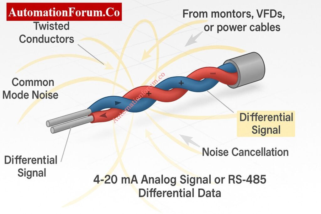
Engineers use twisted pair cables to keep things working in such extreme electrical conditions, especially when sending 4 to 20 mA analog signals and RS 485 digital communication.

This guide tells you how twisted pair cables function, what their benefits are, how to install them correctly, and some examples of how they can be used in process control systems. It also has a short list of things that engineers should think about when choosing parts for remote I/O and communication wiring.

There are a lot of noise sources in industrial automation systems. Electromagnetic interference (EMI) can come from things like variable frequency drives (VFDs), contactors, relays, soft starters, and even fluorescent lamps. This EMI couples into signal cables, especially those that transmit low-level digital or analog signals.

When interference couples into signal wiring, it can result in:

  • Incorrect analog current readings in 4 to 20 mA loops
  • Corrupted data in serial communication lines such as RS 485
  • Spurious alarms and unstable control loops

So, one of the most important things to think about when designing instrumentation and control systems is how to reduce the effect of noise on signal wiring.

How Twisted Pair Cable Cancels Electrical Noise

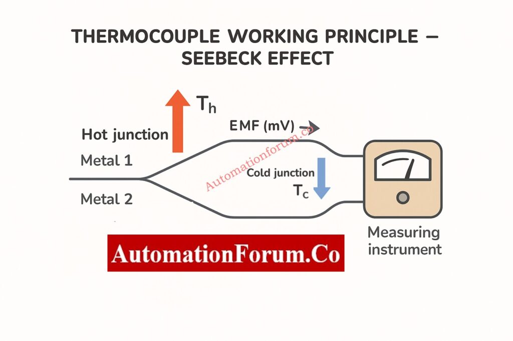
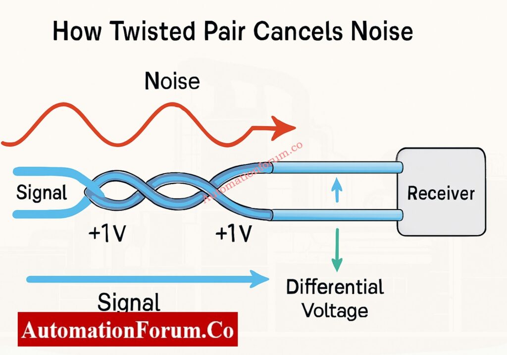
Two conductors are wrapped around each other along the length of a twisted pair cable. These conductors carry the same signal, but one is positive and the other is negative compared to a reference potential.

When an electromagnetic field from outside the cable affects it, it makes the voltages in both conductors almost the same. The common interference goes away because the receiver measures the difference in voltage between them. This is what is known as common mode noise rejection.

If noise from outside causes both wires to have +1 volt, the difference between them stays the same. The receiver cancels out the interference by subtracting one from the other.

This basic geometric twisting of wires makes the signal much stronger, especially over long distances in places where there is a lot of electrical noise.

The amount of twists per meter affects how well noise suppression works. More twists indicate that electromagnetic interference is less likely to happen.

For industrial signal cables:

  • Cables with 6 to 10 twists per foot are usually used for low-frequency analog signals like 4 to 20 mA loops.
  • To reduce reflection and cross talk, high-speed digital signals like RS 485 or RS 422 often need tighter twisting and controlled impedance.

Manufacturers keep the twist rate the same so that both conductors get the same amount of interference, which keeps the signal balance.

Why Engineers Prefer 4–20 mA Over Voltage Signals: Why 4-20 mA Current Signal is Preferred Over Voltage Signal in Instrumentation?

The 4 to 20 mA current loop is the most common way to send analog process variables including pressure, temperature, and flow. The current signal shows the measured value and is usually supplied from the field transmitter to a PLC or DCS input card.

In current loops, voltage drops caused by cable resistance and noise can make measurements wrong. Using a twisted pair cable lessens these impacts by:

  • Lessening the chance of noise coupling from power wires that are close by
  • Keeping the loop resistance the same and stopping measurement drift
  • impacts by:
  • Making it less likely for noise to come from neighboring electrical wires

Even though voltage signals are more vulnerable to noise than current loops, twisted pair cable makes sure that everything is accurate and stable in even the most severe industrial conditions.
Instantly Calculate Process Value from 4–20 mA Transmitter Output: 4 to 20 mA Transmitter Output Process Value Calculator

In industrial networks like Modbus RTU, Profibus, and BACnet, RS 485 is a common way to communicate differentially. In RS 485, data is sent as a difference in voltage between two wires, which are usually named A and B.

The balance between the two conductors is very important for differential signals. An imbalance can cause signals to bounce off of each other, distort, and make communication mistakes.
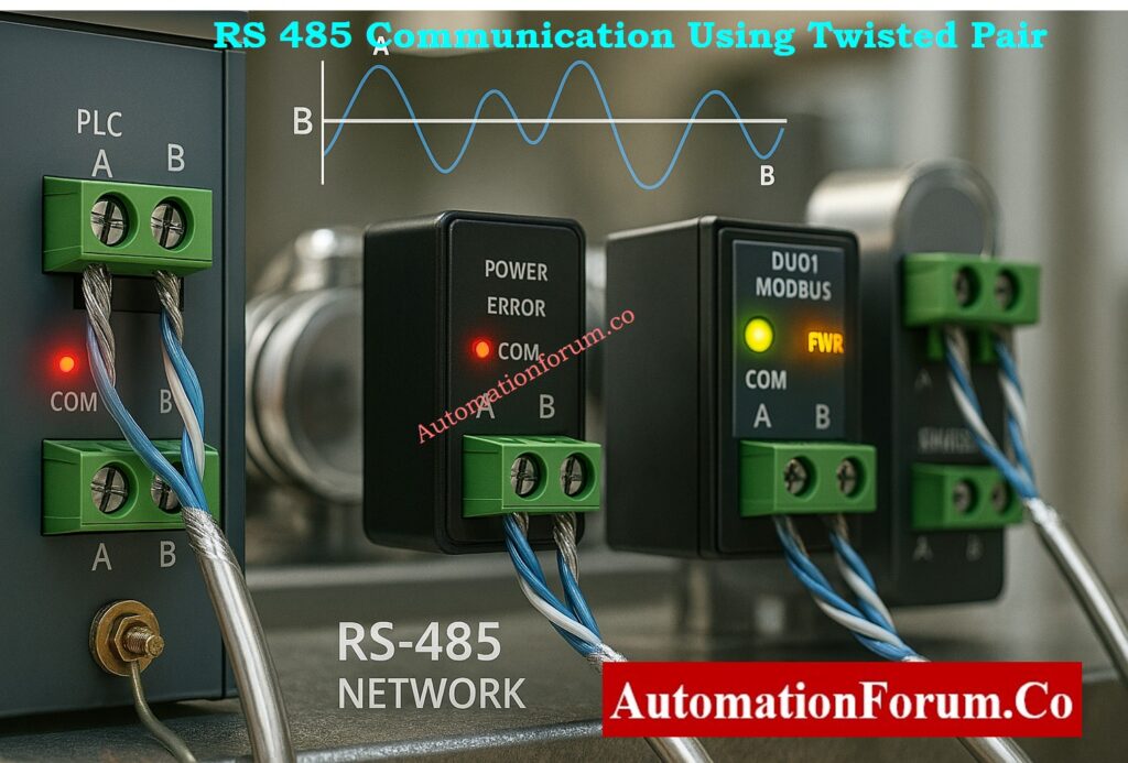
Twisted Pair Cable for RS 485 Communication

Twisted pair cable keeps this electrical symmetry, which means:

  • Characteristic impedance that stays the same (usually 120 ohms)
  • Less electromagnetic radiation
  • Data can be sent over great distances, up to 1200 meters, with no problems.
  • Support for more than one node on the same communication bus

So, a twisted pair connection is required for all RS 485 installations to keep data integrity high and error rates low.
Transmitter Span, LRV, and URV Calculator for 4–20 mA Signal: Transmitter Calibration Span, LRV and URV Value Calculator from Measured 4 to 20 mA

Twisting alone makes noise less likely to affect the signal, but adding shielding makes it even less likely to be affected by outside sources. A conductive covering surrounds the twisted wires in Shielded Twisted Pair (STP) cables. This layer keeps high-frequency noise from getting through.

  • Foil Shield (FTP): A thin layer of aluminum foil around the pair that is good for light industrial or building automation.
  • Braided Shield: Copper strands that are woven together to make the shield stronger and better at blocking EMI.
  • Overall Shield: A layer that covers several twisted pairs. It is utilized in multi-pair instrumentation cables.

To avoid ground loops that can increase noise, always ground the shield at one end only, usually at the control room or cabinet side.

In places with a lot of noise, including near VFDs, MCCs, or power distribution panels, using STP cables makes sure that signals stay clear and reduces downtime caused by interference.

Difference Between Twisted Pair, Shielded Pair, and Coaxial Cable

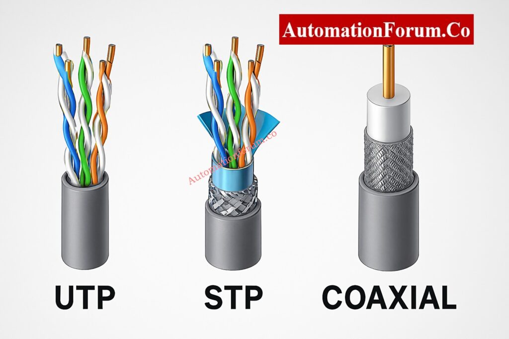
Engineers regularly compare twisted pair, shielded twisted pair (STP), and coaxial cables when they work in factories.

Each type has a different way of being built and protects against noise in a different way.

Cable TypeConstructionNoise ProtectionTypical Use
UTP (Unshielded Twisted Pair)Two insulated conductors twisted togetherGood for low noise environmentsShort 4–20 mA loops or low-speed RS 485 links
STP (Shielded Twisted Pair)Twisted pair with foil or braid shieldExcellent EMI protectionHigh-noise zones, VFD panels, MCC rooms
Coaxial CableCentral conductor with full metallic shieldVery high protection, but single-endedCCTV, RF and instrumentation reference signals
Fiber Optic CableGlass fiber with optical transmissionImmune to EMIHigh-speed communication or hazardous areas

Twisted pair cables are still the best option for sending signals in industry since they reject noise while being flexible and cheap.
Fix Cable Management Issues with Proper Tray Accessories: How to Fix Common Cable Management Issues using Cable Tray Accessories

Proper Cable Routing and Installation Practices - Separation of Signal and Power Cables

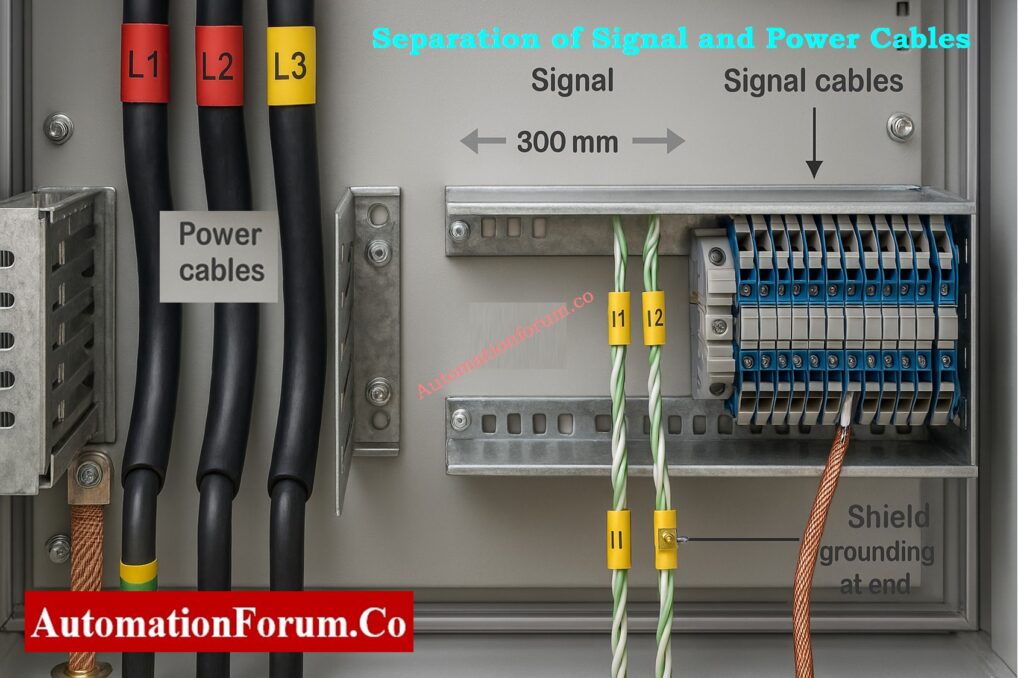
If you don’t do a good job installing the greatest cable design, it won’t work.

When routing and terminating twisted pair cables in industrial settings, follow these steps:

  • Cables for Power and Signal: Keep at least 300 mm (12 inches) away from electricity lines.
  • Use trays or conduits: Put communication and analog signal cables in different metal conduits or cable trays.
  • Don’t run in parallel with power lines: When you have to, cross electricity lines at a 90-degree angle.
  • Label and End Correctly: Label both ends clearly and use the right connectors or terminal blocks to reduce resistance.
  • Keep the Shield Going: If you’re utilizing multi-pair cables, be sure that the shield stays connected at the junction boxes.

Following these wiring guidelines makes sure that the twisted pair cable works as it should and is noise-resistant.

Standard Method Statement for Instrumentation Cable Termination: Method Statement for Instrumentation Cable Termination

Imagine a case where a remote location needs more analog I/O channels, but there is only one spare twisted shielded pair between two places.

RS 485 connectivity modules are one way to fix this:

  • One module at the distant site changes eight 4 to 20 mA inputs into digital Modbus data.
  • Another part of the control room turns the Modbus data back into eight 4 to 20 mA outputs.

This setup lets you send data from many analog sensors over one twisted pair cable, which cuts down on the cost and difficulty of wiring.

Why Cable Shields are Grounded Only at Control Panel Side: Why the Cable Shield is Grounded Only at the PLC or Control Panel Side

Companies like ICP DAS, Advantech, and Wago make small I/O modules that work with Modbus RTU via RS 485. Some even have partnering modes, which let one module automatically reflect the inputs of another without necessitating a PLC or SCADA master.

This method works well for situations when adding Ethernet infrastructure is not possible or cost-effective.

Calculate Temperature Transmitter Output using 4–20 mA Equation: How to Calculate Temperature Transmitter 4-20mA Output Using Linear Equation and Percentage Method ?

When choosing a twisted pair cable for RS 485 or 4 to 20 mA communication, keep the following things in mind:

ParameterRecommended Specification
Conductor MaterialTinned Copper
Conductor Size18 to 22 AWG depending on distance
Insulation TypePVC or XLPE for general use, PTFE for high temperature
Shield TypeFoil or Braided Shield (depending on EMI level)
Impedance100 to 120 ohms for RS 485 applications
CapacitanceBelow 60 pF per meter for long-distance analog loops
Temperature RatingTypically -20°C to +80°C

Choosing a cable that meets both the electrical needs and the climatic conditions makes sure that the signal works the same way all around the plant.
Simulate 4–20 mA Signals Accurately with Loop Calibrator: How to simulate 4-20ma signal with Loop Calibrator ?

There are two ways to send signals: balanced and unbalanced.

  • Balanced transmission, which is utilized in RS 485 and 4–20 mA systems, sends the same signal over two wires that are opposite in polarity.
  • The receiver reads the difference in voltage, which gets rid of noise that is common to both channels.
  • Unbalanced transmission (like RS 232) is more likely to get interference since it employs one signal cable and a ground reference.

Each twisted pair in multi-pair instrumentation cables has a variable twist rate, which is the number of twists per meter.
This design cuts down on crosstalk, which is when signals from two pairs mix together.

  • Short lay length (more twists): Better at blocking noise, utilized for fast transmissions.
  • Long lay length (fewer twists): Good for analog transmissions with low frequencies.

Manufacturers carefully control pair lay to make sure that extended runs of multi-pair cables always work the same way.

Step-by-Step Guide for 4–20 mA Loop Troubleshooting: How to do troubleshooting of a 4-20mA loop?

When engineers want to use twisted pair cables for remote I/O or signal transmission, they can look to the following reliable suppliers and parts:

SupplierProduct Description
ICP DAS8 Channel Analog Input and Output Modules for RS 485
Phoenix ContactShielded Twisted Pair Industrial Cables
AdvantechModbus RTU to Analog Converter Modules
WagoField I/O and Termination Systems
MoxaIndustrial Serial Communication Devices

Before making a purchase, make sure that the I/O modules, communication protocols, and power supply ratings all work together. Also, make sure that the cable you choose can handle the noise and distance requirements of your application.
Compare Twisted Pair, Fiber Optic, and Coaxial Cables: Difference between Twisted Pair,Fiber Optic and Coaxial cables

For safety and signal integrity, it is very important to keep capacitance and inductance in cables as low as possible in intrinsically safe (IS) circuits.

Twisted pair cables meet the standards of IEC 60079-14 and the FISCO model for Fieldbus systems by lowering loop area and energy storage.

When using twisted pair cables in IS areas:

  • Keep shields away from systems that aren’t IS.
  • Keep IS and non-IS trays apart from each other.
  • Common Protocols for Industry Using Twisted Pair
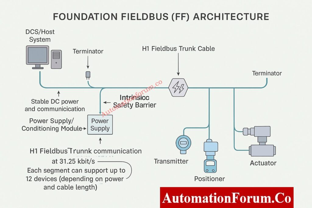
A lot of automation networks use twisted pair transmission in addition to RS 485 and 4–20 mA:

ProtocolMediumMax DistanceNotes
Modbus RTURS 485 Twisted Pair1200 mMost common industrial serial network
Profibus DPShielded Twisted Pair1200 mRequires 150 Ω impedance cable
CANopen / DeviceNetTwisted Pair500–1000 mUsed in machine-level automation
Foundation Fieldbus H1Twisted Pair (31.25 kbps)1900 mSupports power and data on same pair

This range of field protocols shows how important twisted pair architecture is for any current automation.

To make sure that signal transmission systems work reliably and need little maintenance:

  1. In places with a lot of noise, use twisted and shielded cable for all digital and analog signals.
  2. Connect the shield to the ground at only one end, and don’t make more than one ground connection.
  3. When you can, keep cable runs short and straight.
  4. Check the resistance of the cable insulation on a regular basis.
  5. For easy troubleshooting, make sure to follow the right color coding and labeling rules.

Accurate process control and safe plant operation depend on reliable wiring for instrumentation.

One of the biggest problems in industrial automation is electrical noise, and twisted pair cables are a simple but effective way to deal with it.

They are necessary for both analog 4 to 20 mA signals and digital RS 485 transmission because they can cancel out common mode interference and keep differential balance. Twisted pair cables make sure that signals are clear, reliable, and free of interference, even in the toughest industrial settings, when used with the right shielding, grounding, and routing.

If you want your modern plants to be very reliable and keep your data safe, you have to get good shielded twisted pair cables.
Best Practices for Grounding Instrumentation Systems to Reduce Noise: How to properly ground an Instrumentation System to reduce noise?

When designing or upgrading process control networks,

  • Always plan for extra twisted pairs in case you need to add more in the future.
  • Write down the cable routes and the places where the shield is grounded.
  • When utilizing RS 485, put a 120 ohm resistor on both ends to match the impedance and stop reflections.
  • If you have both analog and digital cabling, you might want to use separate multi-pair cables for each kind to reduce interference.

These best practices can help you save a lot of time when you have to troubleshoot and make sure your control system is stable for a long period.

Make sure that the twisted pair cables you choose or install for industrial systems meet certain international standards:

  • IEC 61158: Fieldbus physical layer (Foundation Fieldbus, Profibus)
  • TIA/EIA-485-A: The electrical properties of the RS 485 interface
  • IEC 60332 / IEC 60754: Requirements for cables that are flame-resistant and free of halogens
  • UL 13 and UL 2919 are ratings for communication and instrumentation cables.
  • IEC 60079-14: Choosing and putting in cables in dangerous places

Twisted pair cable is still the most dependable way to send industrial signals, whether it’s from chemical facilities to HVAC control panels, PLC cabinets to field junction boxes.

It shows the idea of making things simple but effective: a minor change that makes a tremendous difference in how well they work.

Always make sure that twisted pair and correct shielding are part of your wiring plan, whether you are building a new control system or upgrading an old one.

Twisted pair cable cuts down on noise that comes from outside sources and makes ensuring that analog current is sent accurately over lengthy industrial loops.

A 120-ohm shielded twisted pair cable is the best choice for RS 485 networks since it cuts down on EMI and keeps the impedance balance.

Twisted pair cuts down on noise by changing the shape of the wires, while shielded twisted pair adds an extra layer of foil or braid for places with a lot of EMI.

Yes, as long as they meet the specifications of IEC 60079-14 and the FISCO model, which usually means they have a blue outer sheath for IS circuits.

With the right 120-ohm impedance cable and end termination, it can go up to 1200 meters.

Advanced Quiz on Thermocouple Troubleshooting in Process Area

0
Advanced Quiz on Thermocouple Troubleshooting in Process Area

Thermocouples are the most important tool for measuring temperature in process industries. However, when readings go wrong, fixing them becomes both an art and a science. This advanced quiz tests your understanding of your area by giving you real-life troubleshooting problems from refineries, chemical plants, and power stations. The questions are meant to see how well you comprehend open circuits, cold-junction problems, grounding faults, signal drift, and calibration discrepancies. This quiz will help you become more confident and better at diagnosing problems with thermocouples in the field, whether you work as a maintenance engineer or a commissioning specialist. Get ready to deal with real-life situations where every degree matters!

Advanced Quiz on Thermocouple Troubleshooting in Process Area

Advanced Quiz on Thermocouple Troubleshooting in Process Area

Advanced Quiz on Thermocouple Troubleshooting in Process Area
Great job! You’ve put your thermocouple troubleshooting skills to the test in real-life situations. Each question is based on problems that real process plants have, like wiring polarity and grounding loops. Keep improving your diagnostic methods to make sure that every industrial setting has safe processes and reliable temperature control.

1 / 25

A thermocouple installed in a reformer furnace shows a steady 250°C even after furnace shutdown and cooldown. The cable and transmitter test normal, and the sensor body is cold to touch. What’s the most likely cause?

2 / 25

A dual thermocouple installed in redundant loop shows mismatch between channels. Both are Type K. Why?

3 / 25

In an ammonia synthesis loop, a Type K thermocouple installed in a thermowell reads 80°C lower than expected. When checked with a handheld calibrator at junction box, the mV matches correct temperature. What does this indicate?

4 / 25

A thermocouple in a distillation column shows slow temperature rise after startup. Possible issue?

5 / 25

A thermocouple shows correct mV on multimeter but wrong DCS reading. Cause?

6 / 25

Why should thermocouple transmitters be mounted near sensors?

7 / 25

A Type N thermocouple installed in a gas turbine exhaust shows sudden jumps of +200°C whenever a nearby variable-frequency drive (VFD) starts. Shielding and grounding appear correct. Cable length is 80 m. What’s the most probable root cause?

8 / 25

A thermocouple installed near a hydrogen reformer furnace frequently fails within weeks — open circuit each time, even with high-quality MI cable. What’s the most probable reason?

9 / 25

A batch reactor has two redundant thermocouples wired to different transmitters. During a CIP (Clean-In-Place) cycle, both readings suddenly jump by +100°C for 10 seconds, then normalize. No process heat applied. What’s the likely reason?

10 / 25

When a thermocouple is installed in a moving fluid line, poor response time indicates:

11 / 25

Thermocouple insulation damage at high humidity may cause:

12 / 25

A thermocouple transmitter shows 20 mA output for a cold line. Cause?

13 / 25

What’s the effect of connecting thermocouple shield at both ends?

14 / 25

Why do thermocouple readings drift over time in high-temperature service?

15 / 25

A transmitter shows burnout indication. The thermocouple was verified good. What should be checked next?

16 / 25

In a batch reactor, a thermocouple signal drops suddenly to zero during cleaning cycle. Why?

17 / 25

A thermocouple shows reading only when the transmitter body is touched. What’s the likely fault?

18 / 25

A grounded thermocouple shows erratic spikes when connected to PLC. What is the best corrective action?

19 / 25

A high-pressure reactor thermocouple reads 60°C lower than expected during a heat-up cycle. Calibration and loop check are perfect. Process engineer confirms no heat loss. What’s the next best diagnostic step?

20 / 25

Two thermocouples on the same process show different readings. Both verified okay in calibration. Possible reason?

21 / 25

A thermocouple is reading 50°C higher than actual. Reference junction compensation is internal. What could cause this?

22 / 25

In a vacuum distillation column, a thermocouple installed inside a long thermowell shows sluggish and damped response compared to another nearby probe. Process temperature fluctuates rapidly. What should be checked first?

23 / 25

During maintenance, the polarity of thermocouple extension cable was reversed. What symptom would appear on the control system?

24 / 25

During startup of a fired heater, a Type K thermocouple connected to a safety interlock system shows a steady 400°C while actual flame temperature exceeds 800°C. The interlock didn’t trigger. Field check shows 8.5 mV output. What’s the root cause?

25 / 25

A type K thermocouple in a reactor shows 0°C on DCS though process is 250°C. Loop test shows 0 mV. What’s the most probable fault?

Your score is

The average score is 65%

0%

Access 1000+ MCQs tailored for instrumentation engineers: Instrumentation and Process Control Quiz Hub – 1000+ MCQs for Engineers

Tags

#Thermocouple, #InstrumentationQuiz, #TemperatureMeasurement, #Troubleshooting, #ProcessInstrumentation, #MaintenanceEngineer, #ColdJunction, #GroundLoop, #IndustrialAutomation

Foundation Fieldbus Installation and Best Practices – Complete Guide for EPC and Maintenance Engineers

0
Foundation Fieldbus Installation and Best Practices – Complete Guide for EPC and Maintenance Engineers

Foundation Fieldbus (FF) is a strong digital communication technology that is commonly used in process automation to connect smart field instruments, control systems, and junction boxes. FF sends both power and digital transmission across a single pair of wires, which is different from the standard 4-20 mA analog loops.

This below article has a complete installation checklist and best practices for EPC engineers and maintenance teams to follow to make sure that signals are sent reliably, noise is kept to a minimum, and the system stays in good shape over time.

Learn how the FISCO model ensures safety in Fieldbus Intrinsically Safe Concept (FISCO) Model for Foundation Fieldbus H1 and Profibus PA

Understanding Foundation Fieldbus Architecture

Foundation Fieldbus is a digital system with two wires that runs on a bus at 31.25 kbit/s and is meant for distributed control.

A typical FF segment includes:

Major Components of an FF Segment
  • H1 Fieldbus Trunk Cable: Sends and receives data and DC power.
  • Terminators: There are two per section, one at the DCS/host end and one at the conclusion.
  • Power Supply / Conditioning Module: Keeps the bus voltage steady.
  • Junction boxes and barriers keep things separate, safe, and orderly at the ends.

Depending on the length of the connection and the power budget, one FF segment can support up to 12 devices.

Understand the working principles and features of Foundation Fieldbus H1 Technology

Foundation Fieldbus Cable Selection Guide
  • Conductor: 18 AWG (0.8 mm²) for the best signal transmission and the least amount of voltage drop over long distances.
  • Impedance: 100 Ω ±20% to keep the signal strong across the network.
  • Capacitance: less than 100 pF/m to make sure that signals don’t become distorted and data is sent reliably.
  • Shield: Aluminum/polyester foil with a drain wire for better EMI protection and more reliable grounding.

Note: Type B or C cables should only be used for short distances because they make noise and weaken signals.

  • Construction: A shielded, twisted pair cable with one drain wire for grounding.

Multi-Pair Armored Cable: Used to connect trunk lines or major segments.

  • Construction: Each pair has its own shield, and there is also an overall shield and drain wire for extra safety.

Gain complete insight into the communication layers of Foundation Fieldbus Protocol Basics

  • Always use Type A Foundation Fieldbus (FF) wires for both trunk and spur wiring.
  • To stop reflections, keep the impedance the same over the whole section.
  • Before you install, make sure the drain wire is still connected and the shielding is still in good shape.
  • Don’t use cables that are rated for high voltage (like 600V) in FF circuits because they create unneeded capacitance.
Foundation Fieldbus Installation Best Practices

More than 90% of FF communication problems are caused by bad cable preparation or wiring the wrong way. The following best practices will make sure that commissioning goes smoothly.

  • To reduce interference, keep FF wires apart from power, PA, and relay lines.
  • Keep at least 300 mm of space between 230/440 V AC cables.
  • Follow the rules for separating trays: keep instrument signal trays separate from power trays.
  • Don’t put too much stress, twist, or sharp bends on the installation.
  • To keep the conductor safe, the minimum bend radius must be at least 10 times the cable diameter.
  • To keep impedance stable, never bend the tray corners more than 70 to 110°.

Improve your hazardous area design knowledge using Intrinsic Safety Protection Systems: Understanding Ex ia, Ex ib, and Ex ic

  • Keep the shield’s integrity intact from the source to the end point.
  • Stop the shield at just one end, usually at the DCS or power conditioner end.
  • Make sure the shield is isolated at both ends of the device to stop ground loop interference.
  • Never connect the drain wire to the metal casing or housing of field equipment.
  • Individual and overall shields must stay continuous and correctly terminated for multi-pair cables.

Learn how to differentiate key control elements in Understanding the Difference Between DCS Components: ES, OS, and AS

Foundation Fieldbus Cable Preparation and Termination

Preparing cables correctly makes sure that signals stay strong and EMI doesn’t get through.

  1. Take off the outer jacket gently so that you don’t cut the inside insulation.
  2. Do not damage the inner insulation or mylar foil when you strip armored cable.
  3. Don’t cut the shield foil or drain wire until they are attached to the terminal blocks.
  4. To cut down on electromagnetic pickup, make the exposed conductor as short as possible.
  5. Use heat shrink tubing (25–40 mm) to cover cuts in the jacket and keep shields separate.
  6. For long-lasting identification, use printed heat-shrink sleeves instead of sticky labels.
  • Only take off the jacket length that is needed for gland insertion.
  • Orange means positive, and blue is negative.
  • Use fork terminals with vinyl insulation for stranded wires.
  • Make sure that all terminal screws are tight.
  • Make sure the shield doesn’t touch the transmitter body or the gland metalwork.

Discover the core definition and function of What is FOUNDATION Fieldbus ?

  • Used for barrier spur terminations or multiplexer transmitters.
  • Use the right armor termination: M25 for 2-pair cables and M20 for single-pair cables.
  • Check the accuracy of the trunk input polarity and label.
  • Only keep the shield going up to the junction point.
  • Used in areas that need surge protection or are dangerous.
  • Do the same things to get ready as you would for barrier junction boxes.
  • Make sure that the trunk and spur ends on Relcom or P+F MegaBlock connectors are right.
  • Houses FF boundaries that keep people safe by separating them from each other.
  • Each barrier can hold up to four spurs.
  • Check the polarity: Orange (+) and Blue (–).
  • Check that the LED lights (Power ON, Fault OFF) are on and that the spur voltage is at least 11V DC.
  • If you utilize an external TP-32 terminator, turn off the internal terminators.
  • It connects marshalling cabinets to field junction boxes.
  • Neatly terminate incoming 5-pair trunk cable on indicated terminals.
  • Send outgoing single-pair cables to each field section.
  • Put spare pairs on terminal blocks that aren’t being utilized right now so you can use them later.
  • Keep the trunk and spur shields separate from each other.
  • Use ferrules and the right color codes to make it easy to tell which segment is whose.

Compare signal transmission methods and system advantages in Comparison between Conventional (4-20ma) connection, Foundation-Fieldbus, and HART?

Grounding is important to get rid of noise that comes from outside and make sure that communication works.

  • At the marshalling panel, connect the overall trunk shield to the instrument ground.
  • The connector for the FP-32 shield should connect to each segment shield.
  • At the IJB, keep the trunk and spur shields separate.
  • Make sure that the TP-32 terminator earth is connected to the plant earth grid.
  • Check all of the earth points on a regular basis for paint insulation or rust.
  • Connect all the FF device earth points directly to the plant instrument earth.
  • Make sure the tray stays together by welding or bolting the seams tightly.
  • Fix any joints that are rusted or corroded to keep the grounding safe.
  • Don’t use floating trays that cut off the main earth grid from the FF device grounds.

Explore the communication concept and industrial importance of What is Fieldbus?

  • Check that all connections are correct (Orange = +, Blue = –).
  • Check the polarity of the TP-32 terminator: Red (+) and Black (–).
  • Only use two terminators, one at either end of the segment.
  • Check the inside of JB for moisture, rust, or condensation.
  • Use glands with an IP rating to keep anything from getting in.
  • Put in breather drains in places where the air is very humid.
  • Instead of sharp wire ties, use wide nylon or steel straps.
  • To make sure the metal-to-metal contact is solid, clean the earthing lugs and take off any paint.

Follow a step-by-step instrumentation guide on How to calibrate Fieldbus transmitters?

  • Use heat-shrink coverings to clearly label cables near both ends.
  • Keep up-to-date cable schedules and as-built drawings.
  • Write down the segment numbers, the locations of the terminators, and the JB references.
  • Ground spare trunk pairs correctly to keep noise from getting through.
  • Do physical layer tests when you first set up:
    • Bus voltage
    • Jitter level
    • Signal quality index (SQI)
    • Retransmission rate
    • Error codes
  • Use regular cable glands and stripping tools.
  • Keep the shield going over all parts.
  • When routing, make sure to follow the minimum bend radius.
  • Check the polarity at either end.
  • Use sleeves with printed information.
  • Keep the cable trays attached to the ground grid.
  • Do not put FF cables and power wires in the same tray.
  • Don’t ground shields on both ends.
  • Don’t bend wires too much or go beyond the angle limits.
  • Don’t let shields stay floating or unconnected.
  • Don’t use thin wire ties that will hurt the insulation.
  • Don’t forget about corroded tray joints or drifting grounds.

Post-Installation Verification and Testing

Before commissioning each segment:

  • Check the voltage on each spur (at least 11 V DC).
  • Make sure that terminators are only placed twice for each segment.
  • Check that the segment can talk to all of the live-listed devices.
  • Use portable Fieldbus diagnostic equipment to record the shape of the signal.
  • In the FF installation report, write down the test findings.
  • Every year, check all of the FF junction boxes and cable trays.
  • Make that the shield, grounding, and corrosion are all in good shape.
  • Use FF diagnostic tools to check the noise levels and signal strength from time to time.
  • Keep track of communication issues between devices and fix wiring problems right away.
  • Take care of the environmental protection (JB covers and gaskets).

For the system to work well and the signals to stay clear, it is very important to follow the right steps when installing and wiring Foundation Fieldbus.

Engineers can make sure of the following by following this detailed checklist:

  • High communication integrity
  • Reduced downtime
  • Improved diagnostic performance
  • Long-term plant safety and reliability

Enhance troubleshooting and diagnostic field skills through Closed-Loop Control Valve Troubleshooting: HART, Fieldbus and Diagnostics Skills Quiz

Foundation Fieldbus Installation Checklist (Downloadable Excel)

In process industries, FOUNDATION Fieldbus is a digital communication system. It lets field devices like transmitters and valve positioners talk to each other and share data over just one pair of wires. It transmits both electricity and digital transmission, which is different from regular 4–20 mA signals.

The overall length of the cable for a FOUNDATION Fieldbus H1 segment, including the trunk and all spurs, can be up to 1900 meters.

No. The standard 4–20 mA analog signal is not used by FOUNDATION Fieldbus.

It sends a digital signal that can send various variables and diagnostic information over the same two wires.

Using Type A twisted-pair cable, the usual maximum distance for a FOUNDATION Fieldbus section is 1900 meters.

This limit may be lower in locations that are inherently safe or dangerous, depending on the design of the system and the power source.

In a DCS (Distributed Control System), FF stands for the FOUNDATION Fieldbus network, which connects smart instruments directly to the control system using digital communication.

Test and expand your advanced instrumentation knowledge with Foundation Fieldbus Communication Protocol Advanced Quiz for Instrumentation Engineers

Types of Fire and Gas Detectors – Working Principles and Industrial Applications

0
Types of Fire and Gas Detectors – Working Principles and Industrial Applications
Fire and Gas Detection Systems

An integral feature of industrial safety automation is a Fire and Gas Detection System (FGS), which is meant to constantly watch for and respond to gas or fire releases. It is an important part of the Safety Instrumented System (SIS) or Emergency Shutdown (ESD) design of a facility.

These systems are the first line of defense against disasters in large industrial places like refineries, petrochemical complexes, offshore platforms, and power plants.

fire and gas system architecture
  • Detect flammable and toxic gases in process and utility areas all the time. This can help you find any leaks or problems before they get worse.
  • Detect smoke, flames, or an unusual spike in temperature that shows a fire is starting so that you can respond quickly and manage it.
  • Control panels and field equipment can sound and show alarms, directing people to safe exits and corrective actions.
  • Automatically turn on things like deluge systems, fire suppression units, emergency isolation valves, or ventilation shutdowns to limit the damage.
Fire and Gas Detectors Classification

🔥 Fire and Gas Detectors Classification 🔥

FIRE & GAS DETECTION SYSTEM (FGS)
Safety Instrumented System (SIS)
💨 GAS DETECTORS
🔥 FLAMMABLE GAS
Measured in % LFL
⚙️ Catalytic (Pellistor)
Oxidation Principle
📡 Infrared (IR)
3.4 µm wavelength
📏 Open Path IR
Up to 200m coverage
☠️ TOXIC GAS
Measured in ppm
🔋 Electrochemical Cell
H₂S, CO, Cl₂, HF
💎 Semiconductor (MOS)
Metal Oxide Sensor
🔥 FIRE DETECTORS
💨 SMOKE DETECTORS
⚛️ Ionisation Type
Americium-241
💡 Photoelectric Type
Tyndall Effect
🌡️ HEAT DETECTORS
📍 Fixed Temperature
70°C / 90°C
📈 Rate-of-Rise
Rapid temp change
⚖️ Rate-Compensated
Combined method
🔥 FLAME DETECTORS
☀️ UV Flame
Ultraviolet radiation
🌈 Single IR
Infrared radiation
🔄 UV/IR Combined
Dual technology
🎯 Triple IR (IR³)
Advanced algorithm
🔗 SMART INTEGRATION
4-20mA | HART | Modbus | Fieldbus | ESD/SIS
automationforum.co

Fire and gas detectors are mostly grouped by the kinds of dangers they are meant to find. There are two main groups:

  • Gas detectors, which can tell if there are flammable or poisonous gases around.
  • Fire detectors pick up on signs of fire, like smoke, flames, or heat.

Each category uses special detecting technologies that are best for certain manufacturing environments and hazards.

Learn the Real Importance of Fire and Gas Detection Systems in Industries: Importance of Fire & Gas Detection System

Gas detectors are very important since they constantly check the air for dangerous or combustible gases. They are typically split into two primary types based on how they are used and what kind of gas they are:

  • Flammable Gas Detectors
  • Toxic Gas Detectors

Master Intrinsic Safety Systems – Ex ia, Ex ib, and Ex ic Explained: Intrinsic Safety Protection Systems: Understanding Ex ia, Ex ib, and Ex ic

Flammable gas detectors are made to check how much combustible gas is in the air. Most of the time, the measurements are given as a percentage of the Lower Flammable Limit (LFL) or the Upper Flammable Limit (UFL).

These detectors are very important for stopping explosions and fires by giving early warnings in places where hydrocarbons are processed, compressors are used, and storage facilities are used.

Common technologies used to find flammable gas:

  • Catalytic (Pellistor) Gas Detectors
  • Infrared (IR) Gas Detectors
  • Open Path (Line-of-Sight) Infrared Gas Detectors
Flammable Gas Detectors

Working Principle:
Catalytic gas detectors work on the oxidation principle, which means that combustible gases touch a heated catalytic bead. This contact causes fire, which makes heat. The Wheatstone bridge circuit’s electrical resistance varies when the temperature goes up, which lets the detector read gas concentration correctly.

Key Features and Applications:

  • Very good at detecting hydrocarbon gases like methane, propane, and butane that are often present in oil and gas operations.
  • Works best in places with a lot of oxygen, where catalytic oxidation can happen quickly.
  • Needs to be calibrated every so often to make sure it is accurate, especially in places where silicones or sulfides could poison the sensor.

Typical Alarm Settings:

  • Low Alarm: 20% LFL (Early warning of gas presence)
  • High Alarm: 60% LFL (Critical gas level demanding immediate action)

Working Principle:
Infrared gas detectors measure how much infrared radiation is absorbed at certain wavelengths. A reference wavelength that isn’t impacted by gas is used to compare hydrocarbon gases, which absorb IR light at about 3.4 µm. The ratio of these two readings gives a precise measure of gas concentration, regardless of how old the sensor is or how strong the source is.

Advantages and Applications:

  • Works well even in places with low oxygen levels, when catalytic detectors might not work.
  • Not affected by typical poisons including lead, silicones, and sulfur compounds.
  • Commonly used in refineries, offshore facilities, gas turbine enclosures, and LNG plants where dependability and quick reaction are very important.
  • Low Alarm: 20% LFL
  • High Alarm: 60% LFL

Working Principle:
Open Path detectors send a beam of infrared light over extended distances (up to 200 meters) from a transmitter to a receiver. Any gas that can catch fire that gets inside the beam path takes in some of this IR energy. To find the total amount of gas in that area, you utilize the amount of absorption.

Benefits and Applications:

  • Covers a lot of ground in big open regions, making it great for outdoor installations where point-type detectors might not work.
  • Responds very quickly to large gas leaks, which helps lower the risk of an explosion.
  • Used a lot on offshore process decks, compressor stations, and tank farms.

Typical Alarm Setpoint:

  • 0.5 LFL·m (Equivalent to 50% LFL over one meter)

Learn How Lower Explosive Limit (LEL) Determines Gas Safety Boundaries: Understanding Lower Explosive Limit (LEL)

Toxic gas detectors find hazardous gases that can hurt your health right away or put you at risk of long-term exposure. Parts per million (ppm) is the usual unit of measurement for concentrations. This gives an early warning before they reach harmful levels.

These detectors protect those who work in small places, analysis shelters, labs, and process units that deal with dangerous compounds.

Examples of Toxic Gases Monitored:

  • Hazards to health right away: hydrogen sulfide (H₂S), carbon monoxide (CO), chlorine (Cl₂), and hydrogen fluoride (HF)
  • Benzene, toluene, vinyl chloride, and other volatile organic compounds (VOCs) are examples of chronic exposure hazards.

Download Complete IEC Standards Chart for Instrumentation and Control Engineers: IEC Standards Chart for Instrumentation and Control

Advantages and Applications:

  • It has great precision and gas selectivity, which cuts down on false alarms.
  • It needs little power and lasts a long time with readings that don’t change.
  • Often used in process facilities to find H₂S, CO, and other harmful gasses.

Alarm Settings for H₂S Detectors:

  • Low Alarm: 5 ppm
  • High Alarm: 10 ppm

Working Principle:
When the Metal Oxide Semiconductor (MOS) detector comes into contact with target gases, its electrical resistance changes. The semiconductor’s conductivity changes as gas molecules stick to its surface. The shift that happens is seen as gas concentration.

Advantages:

  • Small, cheap, and good for networks that detect gas in many places.
  • It reacts fast to abrupt gas discharges, so it’s great for keeping an eye on utility corridors or ventilation systems.

Limitations:

  • It is sensitive to changes in temperature and humidity.
  • Not as picky as electrochemical sensors, therefore they need to be adjusted for the environment.

Ace Your Safety Instrumented System (SIS) Interview with Expert Q&A: Safety Instrumented System(SIS) Interview Questions and Answers

Fire Detectors

Fire detectors pick up on smoke, heat, or flames to let you know about fires before they happen. These detectors are very important for both indoor and outdoor use since they protect people and property.

Fire detectors are classified into three main types:

  • Smoke Detectors
  • Heat Detectors
  • Flame Detectors

Smoke detectors may pick up small particles or fumes from burning things in the air. They work especially well for finding fires early in small locations like control rooms, substations, and office settings.

Main Types of Smoke Detectors:

  • Ionisation Smoke Detectors
  • Photoelectric (Optical) Smoke Detectors

Working Principle:
An ionization smoke detector has a small chamber that holds a radioactive source called Americium-241. This source ionizes the air, which lets a continuous current flow between two electrodes. When smoke particles get inside the chamber, they stick to the ions, which stops the current and sets off the alarm.

Applications and Benefits:

  • Great for finding fires that burn quickly and with a lot of energy but don’t make a lot of smoke (like paper or flammable gas fires).
  • Used a lot in data centers, control rooms, and places where electrical equipment is kept.

Download the Ultimate Fire Alarm Detector Coverage Calculator Excel Tool: Fire Alarm Detector Coverage Calculator – Professional Excel Tool for Accurate Detector Placement

Working Principle:
Inside the sensing chamber, this detector has a light-emitting diode (LED) and a photo-diode that are angled. The particles in smoke disperse the light (the Tyndall effect), which lets it reach the photo-diode. The change in the brightness of the light tells the control circuit to set off an alarm.

Applications:

  • This is best for finding smoldering flames that make a lot of smoke but not much heat, like fires in wood, plastic, or fabrics.
  • A lot of warehouses, control buildings, and substations use it.

Heat detectors go off when the temperature rises because of a fire. They function best in places where smoke or dust could set off false alarms, such kitchens or workshops.

Calculate Backup Power Precisely – Fire Alarm Battery Size Calculator: Fire Alarm Battery Size Calculator – Professional Tool for Accurate Backup Power Sizing

  • Fixed Temperature Type: Activates when a specific preset temperature (e.g., 70°C or 90°C) is reached.
  • Rate-of-Rise Type: This kind goes off when the temperature rises quickly over a short period of time, even if the set threshold hasn’t been met.
  • Rate-Compensated Type: This type uses both methods and makes sure that detection is always accurate, no matter how the environment changes.
Flame Detectors

Flame detectors identify fire by sensing radiation energy (UV or IR) emitted by flames rather than smoke or heat. They are designed for high-risk outdoor or process areas such as refineries, fuel storage tanks, turbine enclosures, and hangars.

  • Ultraviolet (UV) Flame Detectors
  • Single Infrared (IR) Flame Detectors
  • Combined UV/IR Detectors
  • Dual IR and Triple IR (IR2 / IR3) Flame Detectors

Key Features:

  • Respond to visible or invisible flames in less than a second.
  • Use powerful algorithms to tell the difference between real flames and false alarms created by sunshine, hot surfaces, or welding arcs.
  • Able to keep an eye on huge open areas, which makes them perfect for offshore platforms, petroleum terminals, and aircraft hangars.

Follow Professional Method Statement for Instrumentation Cable Termination: Method Statement for Instrumentation Cable Termination

Integration and Communication in Fire and Gas Systems

Modern fire and gas detectors are getting smarter and more computerized, and they are made to operate well with plant safety networks.

They talk to each other using several industrial protocols, such as 4–20 mA, HART, Modbus RTU/TCP, or FOUNDATION Fieldbus. They are connected to Fire and Gas Control Panels (FGCPs) or Safety PLCs (such Triconex, HIMA, or DeltaV SIS).

Integrated Functions Include:

  • alarms that can be seen and heard in both the field and the control rooms.
  • Automatic turning on of deluge systems, emergency isolation, and shutting down of ventilation.
  • System diagnostics and fault reporting that happen all the time for preventive maintenance.

Prepare Smartly with Top Gas Turbine Instrumentation Interview Q&A: Top Essential Gas Turbine Instrumentation Interview Questions and Answers

Key Parameters for Selecting Fire and Gas Detectors
Selection ParameterDescription
Detection PrincipleType of sensing method (Catalytic, IR, UV, Photoelectric, etc.)
Target HazardSpecific gas or fire signature to be detected
Environmental ConditionTemperature, humidity, dust, and exposure rating
Hazardous Area ClassificationZone 1, Zone 2 (Exd, Exia, Exe protection)
Output Signal4–20 mA, HART, Relay, Modbus, or Digital
Response TimeTypically within 5 seconds or faster
Maintenance FrequencyRecommended calibration or test interval
CertificationsIECEx, ATEX, FM, UL, SIL compliance


A good Fire and Gas Detection System is the most important part of any industrial plant’s safety plan. Knowing the many kinds of detectors, how they function, and when to use them makes sure that potential dangers are found quickly, so that steps can be taken quickly to reduce the risk.

Regular testing, calibration, and preventive maintenance are very important for keeping systems reliable and making sure they meet global safety standards in the long term.

Discover Why 3-Wire Fire and Gas Detectors Dominate Industrial Safety: Why 3-Wire Type Fire and Gas Detectors are the Preferred Choice in Industrial Safety?

The four main types of fire detectors are smoke, heat, flame, and multi-sensor detectors.

  • Smoke, heat, flame, and multi-sensor detectors are the four basic types of fire detectors.
  • Ionization and photoelectric smoke detectors can pick up smoke particles. When the temperature goes up too much, heat detectors go off.
  • Flame detectors can pick up UV or IR radiation from flames.
  • Multi-sensor detectors can accurately find smoke, heat, and carbon monoxide.

Most gas detectors are either flammable or poisonous.

  • There are catalytic, infrared, and open-path IR types of flammable gas detectors that monitor gases in %LFL.
  • There are two main types of toxic gas detectors: electrochemical and semiconductor. They can find gases like H₂S or CO in parts per million (ppm).

A Type 5 fire alarm system is a manual fire alarm that can only find fires on its own in a few situations. It has manual call points and might only have detectors in high-risk regions. It is usually put in small factories or plants.

Smoke, heat, flame, and gas detectors are the most common types. The Fire and Gas (F&G) system has numerous types of alarms and safety responses that go off when they recognize different fire or gas conditions.

A 4-gas detector is a small instrument that can test four gases at once: O₂, LEL (flammable gas), CO, and H₂S. It makes sure that the air is safe to breathe and finds poisonous or explosive gasses when people are working in tight spaces or doing maintenance.

Explore VESDA Smoke Detection for Early Fire Warning Protection: VESDA Smoke Detection: Advanced Fire Protection with Early Warning Technology

Explained: The Four Main Process Variables (PV, SV, TV, QV) in HART Transmitters – Complete Guide for Instrument Engineers

0
Explained: The Four Main Process Variables (PV, SV, TV, QV) in HART Transmitters – Complete Guide for Instrument Engineers

In the fields of industrial automation and process control, it’s important to be able to measure things accurately and talk to each other reliably. Modern field instruments, especially those that use the HART (Highway Addressable Remote Transducer) protocol, are much more advanced than traditional 4–20 mA transmitters.

HART devices are “smart instruments” that can send digital status information, diagnostics, and various process variables all over the same two-wire loop used for analog signaling.

This guide will show you one of HART devices’ most useful features: the four process variables (PV, SV, TV, and QV). You’ll discover what each variable means, examine examples of instruments in the real world, and see how digital data makes diagnostics and control better in modern plants.
Master the Art of HART Configuration: Best Practices for Configuring HART Parameters in DCS Software

HART transmitter 4–20 mA analog and digital communication diagram

Conventional analog transmitters were limited to transmitting a singular data point, specifically the principal measured variable, by transforming it into a 4-20 mA signal. For instance, a pressure transmitter sends out 4–20 mA for a pressure range of 0–10 bar.
Hands-On Field Guide: Step-by-Step Guide for Installing and Commissioning HART and WirelessHART Devices for Engineers and Technicians

HART communication, on the other hand, adds a digital layer to the analog signal. This means that one transmitter can send up to four process variables (PVs) at the same time:

  • PV – Primary Variable
  • SV – Secondary Variable
  • TV – Tertiary Variable
  • QV – Quaternary Variable

Depending on the type of transmitter, these four variables can be measured, derived, or calculated. They let operators and control systems get to rich, multidimensional data without needing extra wiring or transmitters.
Understand the Secret Behind Reliable Signals: Why is a 250-Ohm Resistor Important for HART Communication?

Depending on the type of transmitter, these four variables can be measured, derived, or calculated. They let operators and control systems get to rich, multidimensional data without needing extra wiring or transmitters.

  • Represents the core measurement function of the device.
  • Mapped directly to the analog output (4-20 mA).
  • Also sent in the HART digital communication frame.
  • Always there in every device that works with HART.

For example, the Rosemount 3051 Pressure Transmitter.

  • Type of instrument: Differential Pressure Transmitter
  • Parameter that was measured: Pressure Difference
  • PV (Primary Variable): Units of pressure: bar, psi, or kPa
  • Output in analog form (4-20 mA): Shows a pressure range of 0 to 10 bar

If the process pressure is 5 bar, the analog signal will be 12 mA, which is in the middle of the range. Simultaneously, the digital HART signal also carries “PV = 5.00 bar” for diagnostic or display purposes.

  • For a Temperature Transmitter, PV = Process Temperature (°C).
  • For a Flow Transmitter, PV = Flow Rate (m³/h).
  • When it comes to a Level Transmitter, PV = Level (in meters or %).

The PV is the principal way for the control system (DCS or PLC) to get input on the process. This variable is necessary for accurate regulation of process conditions in control loops like PID control.

The Secondary Variable (SV) is a second variable that can be monitored or derived from the transmitter. PV is the main measurement, but SV gives you more information that helps you understand how the process is going.

  • Can be a parameter that can be measured directly, like static pressure.
  • It can also be a derived value, such pressure that has been adjusted for temperature.
  • Only accessible through the digital HART signal (not 4-20 mA).
  • Increases overall diagnostic and process knowledge.

Think about the Yokogawa EJX910A Multivariable Transmitter, which is used to measure flow.

In this device:

  • PV (Primary Variable): Differential Pressure (used to figure out flow)
  • SV (Secondary Variable): Static Pressure

Static pressure is a very important variable to have with you. It helps the transmitter adjust for variations in gas density or find line pressure loss, which makes flow estimates more precise.

  • In a temperature transmitter with two RTDs:
    • PV = Sensor 1 Temperature
    • SV = Sensor 2 Temperature
  • In a flow transmitter:
    • PV = Flow Rate
    • SV = Fluid Temperature (used for density correction)

Technicians can keep an eye on more process parameters without adding another transmitter by making the secondary variable available digitally. This lowers the cost of hardware, makes installation easier, and makes it easier to see what’s going on throughout operation.
Test Your Troubleshooting Skills: Closed-Loop Control Valve Troubleshooting: HART, Fieldbus and Diagnostics Skills Quiz

Multivariable pressure transmitter internal sensors for DP, static pressure, and temperature

The Tertiary Variable (TV) is the third variable that can be measured or calculated by the HART transmitter. Depending on the type of equipment, this could be a temperature, density, or even a diagnostic parameter.

  • Usually a parameter that has been derived or measured in an indirect way.
  • Only accessible via the digital HART interface.
  • Not utilized for analog control, but very important for diagnostics and sophisticated monitoring.

Stay Aligned with Global Standards: IEC Standards Chart for Instrumentation and Control

For example, the Emerson Rosemount 3051S Multivariable Transmitter

We should go back to the Emerson Rosemount 3051S MultiVariable Transmitter, which can measure static pressure, differential pressure, and temperature all at the same time.

  • PV: Differential Pressure
  • SV: Static Pressure
  • TV: Process Temperature

Here, the transmitter uses TV (temperature) along with DP and static pressure to compute mass flow or corrected volumetric flow based on fluid properties.

This makes the device an intelligent flow measurement solution combining three sensors into one digital instrument.

  • In a density transmitter, TV could stand for temperature, which is used to make up for changes in density due to temperature.
  • In a level transmitter, TV could stand for vapor pressure, which can affect how accurate the level is in pressurized vessels.

TV gives process control more accurate information by putting it in context. For instance, changes in temperature can have a big effect on the viscosity or density of a fluid. The transmitter allows operators do real-time correction and makes sure accurate measurements by adding temperature as a third variable.

The Quaternary Variable (QV) is the fourth process variable that can be used in HART communication. It is usually a computed, diagnostic, or supplementary parameter that gives further information about the operation or the health of the transmitter.

  • Usually shows calculated numbers like mass flow, density, or total flow.
  • Can also have diagnostic signs, including sensor drift or process variability.
  • Exclusively available through the digital HART signal.
  • Enables predictive maintenance and advanced analytics.

Think about a Multivariable Transmitter, like the ABB 266MST Smart Transmitter, once more.

It measures differential pressure, static pressure, and temperature. From these inputs, the transmitter computes mass flow, which becomes the Quaternary Variable (QV).

VariableDescriptionUnit
PVDifferential Pressurembar
SVStatic Pressurebar
TVProcess Temperature°C
QVMass Flow (Calculated)kg/h

In this setup:

  • The QV = mass flow is derived using DP, static pressure, and temperature, following the compensated flow equation.
  • This single HART device thus replaces three separate transmitters making it a compact and efficient solution for process industries.
  • In a Coriolis Mass Flowmeter (e.g., Micro Motion CMF200):
    • PV = Mass Flow
    • SV = Density
    • TV = Temperature
    • QV = Totalized Flow
  • In a smart density meter:
    • QV could be compensated density at reference temperature.

The QV is the “bonus variable” that makes smart transmitters truly intelligent. It’s what turns raw data into actionable insight helping operators:

  • Detect abnormal conditions early
  • Perform advanced diagnostics
  • Optimize control strategies
  • Reduce the need for additional sensors

Simplify Your Calibration Setup: Wiring Diagram for Pressure Transmitter Calibration in Workbench using HART

One key principle of HART communication is that only the PV is sent via the traditional 4-20 mA analog output.

However, SV, TV, and QV are transmitted digitally over the same pair of wires using frequency-shift keying (FSK) modulation.

This combination allows:

  • Backward compatibility with analog control systems
  • Enhanced digital communication for smart diagnostics

The analog loop keeps legacy systems running, while digital HART data provides real-time access to additional process and device information.
Diagnose Like a Pro: 4-20 mA Loop Troubleshooting with Loop Calibrators : A Practical Guide

HART communication between DCS, transmitter, and handheld communicator

HART connectivity lets modern DCS and asset management systems read all four process variables. Here’s how that helps the plant work better:

BenefitDescription
Improved AccuracyCompensation using secondary and tertiary variables ensures more precise flow, level, and density calculations.
Reduced HardwareOne multivariable transmitter replaces multiple single-variable transmitters, saving installation cost and panel space.
Predictive MaintenanceDigital diagnostics (QV or status variables) alert technicians before failures occur.
Data IntegrationHART variables integrate easily into asset management software like AMS, PRM, or FieldCare.
Operational InsightEngineers can view temperature, pressure, and flow data from one device, enabling better decision-making.

Field Engineer’s Complete Calibration Manual: HART transmitter calibration procedure – For pressure transmitter

Let’s look at how PV, SV, TV, and QV work together in a real-life system for measuring steam flow.

How it works: Steam Flow Measurement in Power Plant Variable

VariableDescriptionFunction in Measurement
PVDifferential PressureUsed to calculate flow rate
SVStatic PressureCompensates for steam density
TVTemperatureProvides temperature compensation
QVMass Flow (Calculated)Final compensated mass flow output
  • The DP sensor monitors how much the pressure drops over an aperture plate.
  • The sensors for static pressure and temperature fix the density of steam.
  • The computer inside the transmitter figures out the mass flow (QV).
  • The DCS gets the 4-20 mA signal for control (PV) and can check digital variables (SV, TV, QV) to keep an eye on things or report on them.

This method makes steam systems more accurate, cheaper to install, and better at managing energy.
See the Real Difference in Communication Protocols: Comparison between Conventional (4-20ma) connection, Foundation-Fieldbus, and HART?

Application AreaExample MeasurementTypical PV/SV/TV/QV Setup
Oil & Gas PipelinesPressure and Temperature MonitoringPV = Pressure, SV = Temperature, TV = Density, QV = Mass Flow
Chemical PlantsReactor Pressure and LevelPV = Pressure, SV = Temperature, QV = Level
Power PlantsSteam Flow MeasurementPV = DP, SV = Static Pressure, TV = Temperature, QV = Mass Flow
Water TreatmentDifferential Pressure Across FiltersPV = DP, SV = Temperature
Pharmaceutical IndustryFlow and Density of LiquidsPV = Mass Flow, SV = Density, TV = Temperature
  • HART transmitters can send out four process variables: PV, SV, TV, and QV.
  • 4-20 mA analog output only sends PV.
  • You can get SV, TV, and QV digitally through HART communication.
  • Each variable can stand for a measured, deduced, or computed value.
  • Accessing all four variables improves accuracy, diagnostics, and maintenance that can be predicted.
  • In modern process industries, multivariable transmitters make installation easier and cheaper.
Infographic of PV, SV, TV, QV process variables in HART device

The idea of PV, SV, TV, and QV in HART devices shows how digital communication has changed process instrumentation.

From a single smart transmitter, engineers can now access multiple data points, perform advanced diagnostics, and integrate intelligent insights into plant control systems all using the same two-wire loop.

Whether it’s pressure, temperature, flow, or density, these four process variables enable a new level of efficiency, reliability, and intelligence in industrial automation.

HART (Highway Addressable Remote Transducer) lets digital signals travel across the 4–20 mA analog signal that is already present in field devices. It lets devices send various process variables, configuration data, and diagnostics without needing more wiring. This makes process control, monitoring, and maintenance more efficient.

The SV (Secondary Variable) in a HART device is the second digital parameter that can be monitored or derived. For instance, in a multivariable transmitter, the PV may be the difference in pressure, and the SV could be the static pressure. You can’t get to SV data through the analog 4–20 mA signal; you have to use HART communication.

The 4–20 mA output of HART transmitters shows the main process measurement, or PV (Primary Variable), which could be pressure, temperature, or flow.

SV (Secondary Variable) is another value that is sent digitally, like static pressure or temperature in the same instrument.

HART variables are the four process variables that a smart transmitter can send digitally:

  • PV – Primary Variable
  • SV – Secondary Variable
  • TV – Tertiary Variable
  • QV – Quaternary Variable

These variables provide you more than one reading (such pressure, temperature, and flow) from one HART instrument, which makes diagnostics and accuracy better.

HART (Highway Addressable Remote Transducer) is a hybrid communication system used in process control. It combines analog (4–20 mA) and digital communication. It lets control systems and handheld communicators read process data, set up instruments, and keep an eye on health diagnostics over the same two-wire loop.

The HART communication standard has a new version called HART 7. It adds support for WirelessHART, better device diagnostics, more reliable connectivity, and more data capabilities for managing assets and doing predictive maintenance in smart plants.

To make digital communication possible, a HART loop needs a 250-ohm resistor to establish the minimum load resistance. The resistor creates a tiny voltage across the current loop. This lets the communicator or control system pick up the HART FSK (Frequency Shift Keying) signal.

HART 5 is an older version of the protocol that lets digital devices talk to each other and set up devices.

HART 7 builds on this by adding WirelessHART support, better diagnostics, event notifications, and better handling of multi-variable data. This makes it better for today’s smart field networks.

Put Your Process Knowledge to the Test: Advanced Multivariable Transmitter Challenge: Flow, Pressure & Temperature Integration

Thermocouple Voltage ↔ Temperature Calculator

0
Thermocouple Calculator – Convert Voltage ↔ Temperature (NIST ITS-90) 1
Thermocouple Voltage to Temperature Calculator – NIST Based
automationforum.co

Thermocouple Voltage ↔ Temperature Calculator

Calculation Results

Powered by automationforum.co
Your trusted source for automation tools and calculators

How the Calculator Works

This calculator uses NIST ITS-90 polynomial equations to accurately convert between thermocouple voltages and temperatures. The conversion process involves:

  • Voltage to Temperature: Applies inverse polynomial equations to convert EMF in millivolts to temperature
  • Temperature to Voltage: Uses direct polynomial equations to calculate the expected thermocouple EMF
  • Cold Junction Compensation (CJC): Automatically adjusts for reference junction temperature

Supported Thermocouple Types

Type Materials Temperature Range Applications
K Chromel-Alumel -270°C to 1372°C General purpose
J Iron-Constantan -210°C to 1200°C Reducing atmospheres
T Copper-Constantan -270°C to 400°C Low temperature
E Chromel-Constantan -270°C to 1000°C Highest EMF
N Nicrosil-Nisil -270°C to 1300°C Improved K-type
S Pt10%Rh-Pt -50°C to 1768°C High temperature, noble metal
R Pt13%Rh-Pt -50°C to 1768°C High temperature, noble metal
B Pt30%Rh-Pt6%Rh 0°C to 1820°C Highest temperature, stable
automationforum.co

Engineers and technicians that work with temperature sensors in industrial automation can use the Thermocouple Calculator, which is an online tool of professional quality. You can use this calculator to change thermocouple voltage (mV) to temperature (°C/°F) and temperature (°C) to thermocouple voltage (mV) in both directions.

It uses the official NIST ITS-90 standard polynomial equations, which give it very high accuracy for all main thermocouple types, including K, J, T, E, N, S, R, and B. The built-in Cold Junction Compensation (CJC) tool makes sure that your results are accurate and take into account the temperature of the air around you.

This tool gives you accurate and traceable thermocouple conversions right away, whether you’re fixing temperature transmitters, checking field readings, or calibrating PLC and DCS input channels.

Thermocouple Voltage ↔ Temperature Calculator 1

A thermocouple calculator is a computerized instrument that makes it easier to figure out the temperature that goes with the little voltage (millivolts) that a thermocouple makes. The metal pair composition of each type of thermocouple determines its own unique relationship between voltage and temperature.

The National Institute of Standards and Technology (NIST) published the ITS-90 (International Temperature Scale of 1990) as a set of established conversion formulas that the calculator employs to make sure it is accurate and can be traced.

This calculator is different from others since it can work in both directions:

  • Voltage to Temperature (to interpret sensor output or monitor process readings)
  • Temperature to voltage (for testing, calibrating, or setting up a transmitter)

This two-way conversion makes it useful for every step of temperature instrumentation, from design to maintenance.

This interactive thermocouple calculator makes it easy to switch between voltage (mV) and temperature (°C or °F) for all typical thermocouple kinds, including K, J, T, E, N, S, R, and B. The tool can convert in both directions, so you can use the same interface to change voltage to temperature and temperature to voltage.

It automatically uses Cold Junction Compensation (CJC) to make sure the results are realistic and accurate in the field. This is quite helpful when your reference junction isn’t at 0°C, which is common in industrial settings. Using the NIST ITS-90 standard, which sets the formal link between thermocouple voltage and temperature for each type, all computations are done.

This calculator makes sure that the results are accurate and can be traced back to the ITS-90 equations. You can use it to check processes, calibrate transmitters, or do rapid tests when troubleshooting in automation systems and instrumentation loops.

Learn the exact method to convert millivolts into temperature using NIST tables and formulas in this detailed guide: How to Convert Thermocouple Millivolts to Temperature: A Step-by-Step Guide

The calculator works with the eight most common types of thermocouples used in process industries:

  1. Type K (Chromel–Alumel) – This is a general-purpose type that works in oxidizing environments and has a temperature range of −270°C to +1372°C.
  2. Type J (Iron–Constantan) is cheap and works well in low-oxygen settings. It can work in temperatures from −210°C to +1200°C.
  3. Type T (Copper–Constantan) is great for cryogenic and low-temperature uses, with a range of −270°C to +400°C.
  4. Type E (Chromel–Constantan) is a thermocouple with a high sensitivity and a range of −270°C to +1000°C.
  5. Type N (Nicrosil–Nisil) is more stable at high temperatures than Type K. It works from −270°C to +1300°C.
  6. Type S (Platinum–Rhodium 10%) is a sensor that may be used in a lab or furnace and has a range of −50°C to +1768°C.
  7. Type R (Platinum–Rhodium 13%) is like Type S but has a little bit more output.
  8. Type B (Platinum–Rhodium 30/6%) is made for places with very high temperatures, up to +1820°C.

Understand the core conversion techniques and see worked examples for real process instrumentation scenarios: Converting Thermocouple Millivolts to Temperature: Methods and Examples

Thermocouple Voltage ↔ Temperature Calculator 2 Seebeck phenomenon

This calculator is based on the Seebeck phenomenon, which says that when two metals that are not the same are heated up at their junctions, they create a voltage (EMF).

To make sure everything is correct, the calculator does these things inside:

First, it uses the chosen thermocouple polynomial to figure out the EMF at the cold junction (reference temperature, usually 25°C).

To convert Voltage to Temperature, it adds or subtracts the cold junction EMF from the observed EMF to get the corresponding EMF at 0°C.

The inverse NIST polynomial is used to turn the total EMF into temperature.

When you do it the other way around, the process temperature you input is first changed to EMF (mV) at 0°C reference, and then the cold junction temperature is taken into account.

The final outcome is a precise temperature or voltage measurement, adjusted for cold-junction effects and compliant with NIST ITS-90 requirements.
Follow this 8-step thermocouple calibration procedure to ensure accurate process temperature measurement: 8 Steps Calibration Procedure for Thermocouple

The International Temperature Scale of 1990 (ITS-90) is the standard that everyone uses for precise temperature measurement and calibration. It tells you how the voltage (EMF in millivolts) of a thermocouple changes with temperature for different types of thermocouples. The National Institute of Standards and Technology (NIST) and metrology labs throughout the world created and maintain ITS-90. It makes sure that all temperature readings can be traced, are consistent, and can be compared around the world.

When this thermocouple calculator changes voltage to temperature or temperature to voltage, it uses the ITS-90 polynomial coefficients that NIST set. This makes sure that every result is in line with calibration data that is accepted around the world. Using the ITS-90 standard is very important for keeping measurements accurate, processes reliable, and following the rules in industrial automation. This makes sure that all readings from transmitters, DCS inputs, or calibration devices use the same temperature scale.
Compare thermocouples vs RTDs with this practical selection guide for process engineers: Choosing Between Thermocouples and RTDs: A Practical Guide for Temperature Sensing

Thermocouple Calculator – Convert Voltage ↔ Temperature (NIST ITS-90) 3

It’s easy to use the calculator, whether you’re changing from mV to °C or °C to mV.

  1. Choose the Type of Thermocouple: Pick the type of thermocouple you want to use (for example, Type K).
  2. Enter the Cold Junction Temperature, which is the temperature of the air around you or the reference temperature (25°C by default).
  3. Choose Conversion Mode and then “Voltage to Temperature.”
  4. Type in the thermocouple voltage in millivolts in the box for “Input Measured Voltage.”
  5. Click “Calculate,” and the calculator will show you the corrected temperature in both °C and °F right away.
  1. Choose the Type of Thermocouple You Need.
  2. Enter the Cold Junction Temperature, which is your reference temperature (25°C by default).
  3. Choose a conversion mode by clicking “Temperature to Voltage.”
  4. Input Process Temperature: Type in the process temperature in °C.
  5. Click Calculate, and you’ll see the right EMF in mV, taking into account cold-junction correction.

This capacity to work in both directions is perfect for both field verification and calibration simulations.

Download or review the complete thermocouple commissioning checklist for installation and calibration accuracy: Thermocouple Commissioning Checklist

  • Dual-Mode Conversion: Use one tool to change voltage to temperature and temperature to voltage.
  • Cold Junction Compensation: Changes the readings automatically based on the reference temperature you entered.
  • NIST ITS-90 Accuracy: For high accuracy, it uses official polynomial coefficients.
  • Celsius and Fahrenheit Output: Shows the temperature in both units for ease of use.
  • 8 Different Kinds of Thermocouples It works with K, J, T, E, N, S, R, and B.
  • Mobile-Friendly Interface: Works perfectly on PCs, tablets, and smartphones.
  • Range Validation: Makes sure that all inputs stay within the NIST-defined boundaries.
  • Quick Calculation: You don’t need to look up tables to get the results right away.

Step-by-step procedure for calibrating thermocouple transmitters with precision instruments: How to calibrate Thermocouple Transmitter?

In real-world thermocouple systems, one junction (the “hot” junction) measures the temperature of the process, and the other junction (the “cold” or reference junction) is at the instrument terminals. The reading changes if the cold junction isn’t kept at a steady 0°C.

Cold Junction Compensation (CJC) fixes this mistake by adding or subtracting the EMF equivalent of the cold junction’s temperature.

Without CJC, your process temperature could change a lot, especially when the weather changes. This calculator has a built-in CJC function that makes sure your readings show the real process temperature, even if your reference junction is at room temperature or higher.

Refer the below link for the Why Thermocouple Reference Junction Compensation(CJC) is Essential for Accurate Temperature Measurement ?

Thermocouple Calculator – Convert Voltage ↔ Temperature (NIST ITS-90) -  Accuracy and Compliance with Standards

The NIST ITS-90 thermocouple tables are used to figure out the voltage-temperature relationships for each type of thermocouple. These polynomials come from a lot of lab calibrations and are the world standard for calibrating thermocouples.

For instance:

  • Type K: −270°C to +1372°C (−6.458 mV to +54.886 mV)
  • Type J: −210°C to +1200°C (−8.095 mV to +69.723 mV)
  • Type T: −270°C to +400°C (−5.603 mV to +20.872 mV)

The calculator verifies your input against these ranges and lets you know if the voltage or temperature you provided is too high or too low. This makes sure that the results are accurate and consistent.
Discover how to choose the correct thermocouple type, sheath material, and junction for your process environment: How to Select the Right Thermocouple for Temperature Measurement Applications?

This tool is meant to be used for a variety of engineering and field operations in many different industries:

  1. Calibration and Simulation:  Use the Temperature → Voltage mode to mimic a thermocouple signal while calibrating the transmitter.
  2. Field Troubleshooting:  If the thermocouple signal doesn’t appear right, use the Voltage → Temperature mode to check if the wiring or sensor is broken.
  3. PLC/DCS Configuration: Engineers can use the calculator’s output to double-check scaling and input ranges when they set up analog input channels.
  4. Maintenance Documentation: Change voltages obtained in the field into temps so they can be added to calibration or maintenance reports.
  5. Training and Education: A great way to learn about how thermocouples work, the Seebeck effect, and how to fix cold junctions.

Even when the math is right, mistakes can happen in the field. Here are some useful tips:

  • No Reading or Wrong Value: Check the polarity of the thermocouple; if the wires are switched, the measurements will be wrong.
  • Unstable Output: To lessen electrical noise interference, make sure the shielding and grounding are done well.
  • Incorrect Temperature: Make sure the calculator has the right cold junction temperature set.
  • Drifting Signal:  Replace thermocouples that are old or have corroded; using them for a long time at high temperatures changes how they work.
  • Out-of-Range Warning: The input might be outside the NIST polynomial range. Please select a different type of thermocouple.
    Learn to simulate temperature sensors with multifunction calibrators for DCS/PLC loop testing: How to simulate RTDs and Thermocouples using Multifunction calibrator?
  • Saves Time: Instant conversion instead of looking up charts by hand.
  • Improves Accuracy:  It uses precise polynomial coefficients instead of estimates.
  • Portable and Free: You don’t have to install any software to use it on any device.
  • Comprehensive: Allows you to change both voltage and temperature in one place.
  • Educational: Helps you learn how thermocouples work and how to use compensating procedures.

This makes it an essential tool for engineers, students, and technicians who need quick access to accurate, standards-based thermocouple data.

The Thermocouple Calculator is a flexible, professional, and simple online tool that can convert voltage to temperature and temperature to voltage using the NIST ITS-90 standard.

It automatically compensates for cold junctions, works with eight different types of thermocouples, and gives you findings right away that are accurate and can be traced. This calculator makes your work easier and more accurate, whether you’re setting up transmitters, checking process temperatures, or studying how thermocouples function.

Go to automationforum.co for more industrial automation tools, calibration checklists, and extensive tutorials on how to use instruments. This is your go-to place for useful engineering solutions.
Follow this step-by-step troubleshooting checklist to identify open circuits, polarity errors, and drift issues: Check List: How to Troubleshoot a Thermocouple?

The Seebeck effect makes a thermocouple work. This happens when two distinct metals are at different temperatures.

The basic formula looks like this:
E = S × (Tₕ − T𝚌)
Here:

  • E = voltage (mV)
  • S = Seebeck coefficient
  • Tₕ = hot junction temperature
  • T𝚌 = cold junction temperature

ITS-90 equations are used by each type of thermocouple (K, J, T, etc.) to get the voltage and temperature right.

The size of a thermocouple depends on the thickness of the wire (gauge) and the diameter of the sheath.

  • Small size (0.2–0.5 mm): fast response, less durable.
  • Large size (1–3 mm): slower response, more durable.
    choose the size based on where you live, how hot or cold it gets, and how much space you have to place it. For the right size, always look at standards like IEC 60584.

Use the NIST ITS-90 polynomial equation or a thermocouple calculator to change millivolt (mV) to temperature (°C).
In simple terms:

  1. Take the thermocouple voltage (mV).
  2. Use cold junction compensation.
  3. To get the correct temperature, use the ITS-90 conversion chart or an online calculator.

The tolerance class of a thermocouple (IEC 60584 or ANSI MC96.1) tells you how accurate it is.
Example for Type K, Class 1:
±1.5°C or ±0.4% of reading (whichever is higher).
So, at 600°C:
0.4% × 600 = ±2.4°C error.
Always check your thermocouple’s class and range for the correct tolerance.

RTDs measure temperature by how the resistance changes with temperature.
For a Pt100 RTD:
Rₜ = 100 × (1 + 0.00385 × t)
Where:

  • Rₜ = resistance at temperature t (°C)
  • 0.00385 = temperature coefficient.
    You can use this simple formula or an RTD calculator to find temperature from resistance.

Refer the below link to test your thermocouple expertise with this advanced quiz covering principles, types, and field applications

Burner Control System Components – Advanced Quiz for Instrumentation Engineers

0
Burner Control System Components - Advanced Quiz for Instrumentation Engineers

In environments like refineries, power plants, and chemical units, Burner Management Systems (BMS) are very important for safe and effective combustion. A BMS keeps an eye on the ignition, flame stability, and shutdown while also enforcing safety interlocks and purge sequences. It helps keep people safe by following NFPA 85, IEC 61508, and IEC 61511 safety rules and lowering the risk of explosions.

A burner control system has both safety and process purposes. Some important parts are:

  • Flame detectors (UV, IR, or rod type) check for flames.
  • Igniters and pilot burners are what initiate the main flame.
  • Control valves for fuel and air control the pace of combustion.
  • Purge valves and interlocks make sure that starting up and shutting down are safe.
  • The BMS controller or PLC runs logic, sequences, and feedback.

These parts work together to automatically fire and safely shut down in case of an emergency.

The right air-fuel ratio is important for efficient combustion. Newer BMS designs use oxygen trim and cross-limited management to keep things running smoothly and cut down on pollution. Integrating with the plant DCS lets you monitor, handle alarms, and run diagnostics in real time.

Automation makes plants safer generally, uses less energy, and minimizes human error.

Burner Control System Components - Advanced Quiz for Instrumentation Engineers

Burner Control System Components – Advanced Quiz for Instrumentation Engineers

This quiz goes into great detail about the instrumentation and control parts that control burner systems in process industries. Check your knowledge of flame detection, ignition systems, safety interlocks, and combustion control logic. This is great for experienced instrumentation engineers and personnel who wish to test or improve their knowledge of burner management systems and other process instrumentation.

1 / 25

What parameter is controlled by the fuel control valve in a modulating burner loop?

2 / 25

In an oil-fired burner system, atomizing air or steam pressure is interlocked primarily to:

3 / 25

Which of the following instruments typically provides a permissive signal to the BMS before ignition?

4 / 25

The main function of a purge interlock in a burner control sequence is to:

5 / 25

In a Burner Management System (BMS), which safety logic ensures that no single sensor failure can cause an unsafe condition?

6 / 25

What is the purpose of a flame failure response time setting in the BMS?

7 / 25

In a cross-limited combustion control scheme, which parameter always leads during a load increase?

8 / 25

A flame scanner based on infrared (IR) sensing is most effective in detecting:

9 / 25

What is the most critical feedback parameter for air-fuel ratio control in combustion systems?

10 / 25

During light-off, why is the burner positioned at “low fire start”?

11 / 25

What condition must be verified before opening the main fuel valve?

12 / 25

Which control loop is responsible for maintaining stable furnace pressure during burner operation?

13 / 25

What is the key safety action taken when a flameout occurs during normal firing?

14 / 25

The BMS will prevent ignition if which of the following is detected as not proven?

15 / 25

Which burner component converts a weak flame signal into a strong, usable control signal for logic processing?

16 / 25

What happens if the air proving switch remains open during startup?

17 / 25

During commissioning, the minimum air setting for purge is verified to ensure:

18 / 25

What type of control loop typically manages combustion air flow in a modulating burner?

19 / 25

In a BMS, what does the term “proving circuit” refer to?

20 / 25

Why is an ultraviolet flame detector unsuitable for oil flames with high smoke density?

21 / 25

The BMS post-purge duration is primarily determined by:

22 / 25

Why must the pilot ignition flame be “proven” before admitting main fuel?

23 / 25

What is the role of a flame safeguard relay?

24 / 25

A parallel positioning combustion control system eliminates which limitation of mechanical linkage systems?

25 / 25

Which parameter is primarily adjusted during burner tuning for optimum efficiency?

Your score is

The average score is 62%

0%

Access 1000+ MCQs tailored for instrumentation engineers: Instrumentation and Process Control Quiz Hub – 1000+ MCQs for Engineers

PLC vs DCS – Which One Should you Choose for your Automation System?

0
PLC vs DCS – Which One Should you Choose for your Automation System? Key Technical Differences Explained

Programmable Logic Controllers (PLCs) and Distributed Control Systems (DCSs) are the two most important control systems in modern industrial automation. They are both used to automate jobs, make things safer, and enhance productivity, but they are fundamentally different in terms of how they are designed, what they are used for, and how effectively they function.

You can choose between a PLC and a DCS based on the type of business you work in, the needs of your process, and your control philosophy. This article talks about the fundamental differences between each system, as well as its advantages and downsides and real-world examples, to help engineers, EPC experts, and automation managers pick the best one.

A PLC is a digital computer that industries use to run machines or specific types of equipment. It works in real time, using programmed instructions like logic, sequencing, and timing to control machines at the machine level.

Originally, PLCs were supposed to replace hardwired relay logic devices. Over the years, they have turned into strong, flexible, and modular systems that can handle intricate automation jobs.

  • Main use: making machines work on their own
  • Common Uses: packing lines, high-speed machinery, robotics, and motion control
  • Response Time: Microseconds (fast and sure)
  • Very high accuracy and precision, suitable for robotics and motion
  • Programming: the IEC 61131-3 standard, which includes Ladder Logic, Function Block, and Structured Text
  • Operating System: An RTOS (real-time operating system)

PLCs are built for discrete industrial processes, where things happen in independent steps, like sorting, welding, or labeling on a packaging line. 

Calculate your PLC power requirements with precision using this complete PLC power sizing guide: PLC Power Supply Calculator – Complete Guide for Accurate PLC Power Sizing

A DCS is a system that keeps an eye on and regulates continuous processes all across the facility. These things can happen in oil refineries, electricity plants, or the making of chemicals. A DCS controls the full plant or process area, however a PLC only controls a few units.

It has a lot of dispersed controllers that are all linked to a fast network for communication. The system makes sure everything works well, gathers data, deals with alarms, and makes things better.

  • Main Use: Making things run automatically at the factory or plant level
  • Controlling operations, acquiring data, interpreting data, and keeping an eye on things from one spot are all common uses.
  • Response Time: From a few milliseconds to a few seconds (slower and not always the same)
  • Moderate accuracy and precision, with safety and dependability coming first
  • Programming: Tools for setting up suppliers (with a focus on process logic)
  • Operating System: Linux and Windows are two examples of operating systems that are used a lot.

DCS is the best choice for processes that run all the time or in batches where dependability, redundancy, and centralized control are very critical.

Discover proven techniques to boost PLC scan speed and optimize your automation performance: How to Increase PLC Speed: 7 Optimization Tips + Advanced Programming Guide

PLC vs. DCS – Detailed Comparison Table
Feature / AspectPLC (Programmable Logic Controller)DCS (Distributed Control System)
Primary UseMachine automationPlant or process automation
ApplicationsRobotics, packaging, motion control, high-speed machineryPower plants, oil & gas, water treatment, process industries
Response TimeMicroseconds (very fast)Milliseconds to seconds
Accuracy & PrecisionVery highModerate (focus on reliability)
HardwareFPGA, ARM, microcontrollers, Industrial PCIndustrial PC with redundancy options
Operating SystemReal-Time OS (RTOS)General-purpose OS (Linux/Windows)
Programming LanguagesLadder, Function Block, Structured TextVendor-specific configuration
System RoleControls individual machines or processesCentralized plant-level monitoring and control
ScalabilityEasy to scale for each machineScales across entire plants and subsystems
RedundancyRarely required (used only in critical machines)Often includes redundancy for 24×7 uptime
Safety & SecurityFocused on equipment safetyFocused on plant safety, reliability, and cybersecurity
Data & IT ConnectivityLimited to machine-level dataActs as gateway to enterprise-level systems and analytics
Best Fit IndustriesDiscrete manufacturing, automotive, roboticsOil & gas, power, chemical, water treatment
StrengthsHigh speed, precise real-time controlCentralized data, reliability, integrated control
LimitationsNot ideal for large-scale process automationNot suitable for ultra-fast motion control
ExamplesMachine controllers, conveyors, robotic armsPlant monitoring, power plants, critical infrastructure

PLCs operate best when tasks are broken down into smaller, repeated processes, like in discrete automation. They are perfect for situations where equipment run quickly and control is definite since they are fast, versatile, and durable.

1. High-Speed Manufacturing Lines
High-speed manufacturing lines, such as bottling facilities where each machine does a distinct step, such filling or capping.

PLCs make sure that machines function together with very minimum delay.

2. Robotic Automation
Robotic arms, for instance, weld or paint cars on production lines.

PLCs manage motion and respond in less than a microsecond.

3. Material Handling Systems
For example, conveyor control systems in the packaging or logistics industries.

PLCs are good for controlling sensors, actuators, and motors.

4. Machine Interlocks and Safety
For instance, press machines or injection molding machines with guards that are locked together and emergency stops.

Safety PLCs are often used to add safety logic to PLCs.

DCS systems are the most important part of continuous or batch process automation, where stability, dependability, and centralized monitoring are very important. They combine many control loops and make sure that everything works together in the plant.

1. Power Generation Plants
Thermal or nuclear power facilities, for example, have hundreds of loops that control things like boilers, turbines, and other equipment.

DCS has a backup, an alarm, and ongoing monitoring.

2. Chemical and Petrochemical Plants
For instance, polymer manufacturers or refineries that always keep an eye on things like temperature, flow, and pressure.

DCS makes sure that processes are effectively managed and that safety

3. Water and Wastewater Treatment
For instance, municipal treatment plants control pumps, valves, and the amount of chemicals that are added.

DCS makes it easier to keep track of things and write down and send in data.

4. Pharmaceutical Manufacturing
For instance, automating the batch process for manufacturers that make APIs or formulations.

You can keep track of recipes, check them, and produce batch reports using DCS.

Master PLC documentation best practices to ensure compliance, reliability, and easy troubleshooting: PLC System Documentation Guide: Essential Records for Industrial Automation Success

PLC vs. DCS –   Key Technical Differences Explained
  • DCS: DCS is both hierarchical and spread out. It has a lot of operator stations, controllers, engineering stations, and historical servers.
  • PLC: Uses fast and reliable industrial protocols like EtherNet/IP, Profibus, or Modbus RTU.
  • DCS: Uses networks that are redundant and cover the complete plant for communication, like Foundation Fieldbus, OPC UA, or Modbus TCP.
  • PLC: These are usually single-CPU systems, although you can add redundancy for key tasks.
  • DCS: It has backup mechanisms at every level, such as controllers, networks, and servers, to make sure it is always available.
  • PLC: Can only handle a modest quantity of data; it usually controls devices in the area.
  • PLC: It grows by adding more controllers to control more machines.
  • DCS: It works on big plants by combining many PLCs and subsystems into one platform.

See the top DCS manufacturers shaping the future of industrial automation: Top 10 DCS manufacturing companies

When designing automation initiatives, the cost is a crucial thing to think about. Over the life of a PLC or DCS system, the expenses of hardware, software, and maintenance are all varied.

  • Less expensive hardware costs for each controller at first.
  • Each system is modular, so you only pay for the I/O modules you need.
  • The costs of integration and engineering go up as the system gets bigger.
  • Good for equipment that can work on their own or small production units.
  • Less expensive hardware costs for each controller at first.
  • Each system is modular, so you only pay for the I/O modules you need.
  • The costs of integration and engineering go up as the system gets bigger.
  • Good for equipment that can work on their own or small production units.

Summary: PLCs are a terrific deal for small or medium-sized automation. DCSs offer a better value for the overall system when it comes to plant-wide control systems.

Find out which PLC brands dominate today’s automation industry and why engineers prefer them: Which PLC is Mostly used in the Automation Industry?

Many modern factories have both PLCs and DCSs. For example, 

  • PLCs quickly control machines.
  • DCS is in charge of coordinating activities at the plant level, gathering data, and giving operators a way to interact with the system. 

In many modern buildings, PLC and DCS systems work together in a hybrid structure to speed things up and keep an eye on everything from one place.

Example – Power Plant Integration:

  • PLCs operate the turbine auxiliaries, boiler feed pumps, and soot blowers in the area.
  • DCS is in charge of coordinating the whole plant, collecting data, setting off alerts, and showing operators what they need to see.
  • Both systems can talk to one other over OPC UA or Modbus TCP, which makes sure that data is exchanged in real time.

With this hybrid setup, PLCs may control machines quickly while the DCS keeps an eye on the whole plant, provides backup, and handles alarms.

Result: All layers of automation are more reliable, visible, and easy to maintain.

AspectPLCDCS
Programming EnvironmentComplies with IEC 61131-3 (Ladder, FBD, ST, IL, SFC)Vendor-specific (typically process blocks that you can drag and drop)
Configuration EffortNeeds someone who knows how to programTemplates make configuration easier.
Engineering FocusLogic and sequencingProcess control and tuning
MaintenanceLess work for small systemsIt’s easier for big systems with central diagnostics.

In general, PLC programming is based on how things work, while DCS setup is based on how things are done.

PLC Maintenance:

  • It’s easy to change out individual modules or CPUs.
  • Less time spent down and less reliance on vendors.
  • Needs a manual backup and documentation for each machine program.

DCS Maintenance:

  • Operator stations can undertake diagnostics and monitoring from a central location.
  • Backups that happen on their own, alerts that keep track of things, and managing firmware.
  • Long-term support contracts from suppliers make sure that updates are constantly available and that the system is always working.

Note: Keep in mind that PLCs are easier to keep up with on-site, while DCSs make it easier to manage the lifecycle of intricate facilities that have extended working lifespans.

Understand PLC hot standby architecture and its benefits for uninterrupted process control: Hot Standby in PLC Systems: Architecture, Working, and Benefits

  • For emergency stop features, use Safety PLCs with a SIL rating.
  • A lot of the time, these are employed in systems that keep machines safe and lock them together.
  • To keep networks safe, they need to be distinct and firewalls need to be set up right.
  • DCS has Safety Instrumented Systems (SIS) and backup control networks.
  • Includes built-in security structures including managing patches, user roles, and segregating networks.
  • Great for keeping important infrastructure (CIP) safe.

Explore how permissive logic and trip interlocks protect equipment and enhance safety in process plants: Understanding Permissive Logic and Trip Interlocks in Industrial Systems

Smart, networked architectures that meet the rules of Industry 4.0 are quickly replacing old industrial systems.

PLCs in IIoT:

DCS in IIoT:

  • Helps with apps for digital twins and analytics at the enterprise level.

By improving performance, reducing energy, and enabling for remote monitoring, the combination of PLC, DCS, and IIoT platforms makes factories smarter.

Learn how to secure your DCS against cyber threats with proven industrial cybersecurity measures: DCS Cybersecurity: Mitigating Risks in Industrial Automation

CriterionChoose PLC When…Choose DCS When…
Application TypeDiscrete, machine-level automationContinuous or batch process control
Response TimeMicroseconds matterSeconds-level control is fine
System SizeSmall to mediumMedium to large, plant-wide
FocusSpeed, precision, and motionSafety, redundancy, and data integration
ScalabilityMultiple independent machinesEntire plant integration
BudgetLower cost per controllerHigher initial cost, but scalable
MaintenanceLocalizedCentralized

The debate between PLC and DCS isn’t about which one is better; it’s about which one works best for your automation needs.

  • If you need rapid, accurate, and predictable control, like in robotics, packaging, or motion systems, choose a PLC.
  • If you need safe, reliable, and centralized process control, like in refineries, power generating, or chemical plants, use a DCS.

In many contemporary construction projects, both technologies work together to create a hybrid design that improves performance, safety, and data management at all levels of operation.

Use this integration checklist to connect third-party systems seamlessly with your DCS: Integrating Third-Party Systems with a Distributed Control System (DCS): Checklist

A PLC is used to control machines at the machine level, while a DCS is used to control processes across the whole plant.

There is no one better than the other; PLCs are best for fast automation, and DCSs are best for managing processes from a central location.

PLCs can work with small process systems, but DCSs are ideal for big plants since they can manage more processes, add more redundancy, and work with more systems.

PLCs are utilized in robotics, packaging, and manufacturing, while DCSs are employed in oil and gas, power generation, and chemical facilities.

Yes. In a hybrid system, PLCs control the equipment and the DCS keeps track of data, alerts, and plant monitoring.

Before deciding between PLC and DCS, think about the scale of the system, the type of process, the reaction time, the requirement for redundancy, and the need for integration.


Thermowell U-Length Calculator | ASME PTC 19.3 TW-2016 Tool

0
Thermowell U-Length Calculator | ASME PTC 19.3 TW-2016 Tool

In every EPC (Engineering, Procurement, and Construction) project, designing thermowells for process instrumentation is an important job. If you choose the wrong length or material for your thermowell, it could give you wrong temperature readings, cause your sensor to malfunction, or even cause your system to vibrate in a way that could be very bad.

Automationforum.co has a robust Thermowell U-Length Calculator that makes it easier to design preliminary thermowells. It is based on simple rules that follow ASME PTC 19.3 TW-2016.

This tool helps engineers figure out the best immersion length (U-length), look at stresses caused by flow, and make sure the thermowell is dynamically stable so that temperature readings are safe and accurate.

This free thermowell U-length calculator will help you find the right immersion length, wake frequency, and vibration safety for measuring temperature in process piping systems.

Thermowell U-Length Calculator
automationforum.co

Thermowell U-Length Calculator

Calculate optimal immersion length based on ASME PTC 19.3 standards

Process Parameters
Thermowell Design Parameters
Calculation Results
Recommended U-Length
Min. Immersion
Max. Allowable
Pipe Inner Diameter
Reynolds Number
Wake Frequency
Natural Frequency
Response Time
Safety Factor
Important Note: This is a simplified calculation for preliminary design. For critical applications, perform detailed ASME PTC 19.3 TW-2016 calculations including steady-state stress, dynamic stress, and fatigue analysis. Consider consulting with a thermowell specialist for final validation.
automationforum.co

Here you can refer more 200+ Online Instrumentation Calculators Collections

A thermowell is a protective cover that goes around temperature sensors (such RTDs or thermocouples) in a process line or vessel to keep them safe from harsh circumstances like high pressure, fast flow, and corrosion.

It lets you change sensors without stopping the operation and makes sure that the temperature is measured correctly while keeping the system's integrity.

The U-length, or immersion length, tells you how far the sensor goes into the process media. Choosing the right U-length makes sure that temperature readings are accurate and that vibrations caused by flow are kept to a minimum.

What Is Thermowell U-Length (Immersion Length)?

Engineers who work on EPC designs have to find a balance between process precision, mechanical safety, and material choice. The Thermowell U-Length Calculator does quick and smart math to help with:

  • Finding the best U-length for the best sensor performance
  • Checking the natural frequency and wake frequency to stop resonance
  • Finding the Reynolds number to look at how the flow behaves
  • Giving safety factors to make sure machines work reliably
  • Supporting Excel reports that can be exported for documentation and approval

Before doing extensive ASME PTC 19.3 TW-2016 thermowell stress and vibration calculations, this tool checks the design.
Get 82 Must-Have I&C Documents: 82 Essential Drawings and Documents for Instrumentation and Control Engineers

Thermowell U-Length Calculation

Here are the primary parameters that this calculator uses, along with their engineering meanings and importance:

ParameterDefinition / Description
Pipe Nominal Size (mm)The nominal diameter of the process pipeline where the thermowell is put in. It figures out how much space is left for input. 50, 80, 100, and 150 mm are common diameters.
Pipe SchedulePipe Schedule Shows how thick the pipe's walls are (for example, STD, XS, XXS). It changes the internal diameter, which affects how easy it is to immerse.
Flow Velocity (m/s)This is the speed at which the process fluid moves through the thermowell in a straight line. When the speed is high, the risk of vibration and wake frequency goes up.
Fluid Density (kg/m³)The amount of mass in a certain amount of process fluid. It changes the Reynolds number and the way things vibrate.
Fluid Viscosity (Pa·s)The fluid's resistance to flow on the inside. It changes the way the boundary layer forms and the stresses caused by flow.
Tip Diameter (mm)The smallest diameter at the end of the thermowell where it senses. A smaller tip makes the response time faster, but it might make the mechanical strength weaker.
Root Diameter (mm)The diameter of the base where the thermowell connects to the process. For structural integrity, it must always be bigger than the tip diameter.
Material SelectionFinds out how strong, resistant to corrosion, and thermally stable a thermowell is. Common materials are SS316, SS304, Inconel 600, and Monel 400.
Sensor Type (RTD / TC)Sensor Type (RTD / TC) tells you what kind of temperature sensor is within the thermowell. For stability, RTDs need to be immersed deeper, although thermocouples respond more quickly.
Process Temperature (°C)Process Temperature (°C) The temperature of the fluid in the process. It affects the choice of materials and the estimates of stress.


Discover Why Thermowells Use 45° Angle: Why Install Thermowells at a 45° Angle? Engineering Logic Explained

Thermowell U-Length Calculator | ASME PTC 19.3 TW-2016 Tool

The calculator gives engineers a full range of outputs that help them understand how thermowells behave in real-world situations.

The advised length of immersion that will give you an accurate temperature reading without too much vibration. Usually between 35% and 40% of the pipe's inner diameter, or less if there are limits on vibration.

The minimum depth needed to make sure that the sensor's tip is fully exposed to the process fluid, which makes it more accurate. Usually, this is the length of the sensor plus 25 mm.

The longest immersion time that keeps the mechanical integrity and avoids resonance circumstances based on the stiffness of the material and the flow forces.

Calculated based on the pipe schedule and nominal size you chose. It changes how much the thermowell can stick out into the flow.

A number without dimensions that describes the flow regime:

Thermowell U-Length Calculator | ASME PTC 19.3 TW-2016 Tool -  Reynolds Number (Re)

where ρ is density, V is velocity, D is diameter, and μ is viscosity.

 If Re is less than 2000, the flow is laminar; if Re is more than 4000, the flow is turbulent.

The number of vortices that form behind the thermowell because to the flow of fluid. Too many wakes close to the thermowell's inherent frequency can produce resonance and fatigue failure.

The natural frequency at which the thermowell vibrates. According to ASME PTC 19.3 TW-2016, safe designs keep the natural and wake frequencies at least 2.2 times apart.

The sensor's response time to a temperature change is affected by the thickness, material, and flow conditions of the thermowell.

Compares the design limits that are allowed with the design limits that are actually used to show mechanical reliability. In process applications, a safety factor of more than 1.5 to 2.0 is usually better.
Understand Thermowell Insertion and U-Length: Thermowell Insertion and Immersion Length

Thermowell U-Length Calculator | ASME PTC 19.3 TW-2016 Tool

This thermowell calculator is based on a simple physics model that is in compliance with industry standards. The basic logic structure employed is as follows:

Pipe Inner Diameter Estimation:
Using internal lookup values, we figured it out based on the nominal size and timetable.

Flow Parameter Calculation:

  • The Reynolds number is based on the flow speed, density, and viscosity.
  • The flow regime helps figure out the wake frequency.

Mechanical Analysis:

  •  The thermowell is treated as a cantilever beam that is pushed and pulled by moving forces.
  • The tip and root sizes affect the moment of inertia and stiffness.
  • The calculator uses the modulus and geometry of the material to figure out the natural frequency.

U-Length Determination:
The tool automatically chooses the lowest value from the pipe limit, vibration limit, and mechanical limit to make sure it is safe.

Thermal Response Estimation:
This uses the thermal mass and heat transfer coefficients to guess how long it will take the sensor to respond.

Safety Factor Computation:
The ratio of the maximum vibration limit to the actual U-length gives a quick reliability index.

MaterialDensity (kg/m³)Modulus of Elasticity (Pa)Allowable Stress (MPa)Application Notes
SS31680001.93×10¹¹138Excellent corrosion resistance; widely used in general process industries.
SS30480001.93×10¹¹138Cost-effective for mild environments.
Inconel 60084702.14×10¹¹207High-temperature strength and oxidation resistance.
Monel 40088001.79×10¹¹172Ideal for marine and caustic service.

Choose Correct Sensor Wet Part Materials: How to Select the Right Wet Part Materials of Sensors in Process Industries

The Thermowell U-Length Calculator is a useful tool for EPC design engineers while they are doing the fundamental and thorough engineering for instrumentation design.

It supports:

  • Preliminary sizing and checking before buying
  • Checking vendor papers and datasheets
  • Technical examination of bids from thermowell providers
  • Combining P&ID and 3D modeling data to plan instrument insertion

Excel output that may be exported makes it easier to examine and approve project documents and QA/QC submissions.
Decode Temperature Transmitter Datasheets Easily: How to Read a Datasheet of a Temperature Transmitter ?

  • The calculator employs basic vibration and heat models that are good for early design work.
  • A complete finite element or ASME PTC 19.3 TW-2016 study must be done for important applications (high speed, long U-length, or high temperature).
  • Based on the pressure in the system, make sure that the process connection strength is good enough (flanged, threaded, or welded).
  • Before finishing the U-length, check the clearance for insertion depth in valves, elbows, or vessels.

Always get final design approval from a thermowell expert or manufacturer.
Reason Behind RTDs Downstream of Orifice: Why RTD Temperature Sensors are Installed Downstream of Orifice Plates?

  • What the Online Thermowell U-Length Calculator Can Do
  • Web interface that works on both desktop and mobile devices
  • Instant Results: dynamic calculation in real time
  • Export to Excel Function: Makes a structured report with all the input and output parameters
  • Print Option: For keeping records of the project
    Error Validation: Ensures logical and numerical accuracy
    Built-in Material Database: For automatic property selection

    Follow This Thermocouple Commissioning Checklist: Thermocouple Commissioning Checklist

For a 4-inch (100 mm) pipe with a regular schedule, a flow speed of 2 m/s, a water density of 1000 kg/m³, and an SS316 thermowell:

  • Minimum Immersion: 75 mm
  • Max Allowable Length: 53 mm
  • Reynolds Number: ~16,000
  • Wake Frequency: 50 Hz
  • Natural Frequency: 120 Hz
  • Safety Factor: 1.9

This makes sure the design is within the limitations for vibration and that the process temperature is measured correctly.

The Thermowell U-Length Calculator from automationforum.co is a dependable design tool for instrumentation and EPC professionals to check the size and performance of thermowells.

It combines basic physics, material attributes, and process dynamics to make it easy to choose the right thermowell quickly and accurately, which saves time during engineering, procurement, and commissioning.

This calculator makes sure that your thermowell design is safe, efficient, and meets the standards set by ASME PTC 19.3 TW-2016, whether you're planning for an oil refinery, a chemical plant, or a power production unit.
Essential RTD Commissioning Checklist for Engineers: RTD Commissioning Checklist

The immersion length, or Thermowell U-length, is the part of the thermowell that goes from the process connection into the fluid stream. The unsupported length is what tells the sensor how deep it can measure temperature in the process.

A U-length thermowell is just a thermowell that is defined by how deep it is immersed. The right U-length makes sure that the temperature sensor is suitably exposed to the process fluid for accurate measurement while also keeping the mechanical stability.

The U-length (or insertion length) is the distance from the bottom of the thermowell mounting connector to the top of the well. It tells you how much of the thermowell is inside the process media.

To get an accurate temperature reading, the thermowell length is depending on how deep it needs to be (typically 1/3 to 1/2 of the pipe's inner diameter).

  • Extra stand-out for insulation or lagging (T-length).
  • Using ASME PTC 19.3 TW-2016 to check vibration and strength by calculating wake frequency and natural frequency.
  • Final length = U (immersion) + T (lagging or stand-out) + connection allowance.

WFC is short for Wake Frequency Calculation. It checks the vibration that happens when fluid flows around the thermowell. The computation makes sure that the thermowell's inherent frequency is substantially greater than the wake (vortex shedding) frequency. This is to prevent resonance and fatigue failure.

The basic design reference is ASME PTC 19.3 TW-2016. This document has guidelines for figuring out thermowell stresses, wake frequency, and natural frequency to make sure that the machine is safe under flow and pressure conditions.

To choose the right thermowell:

  1. Set the process conditions, such as pressure, temperature, speed, and kind of fluid.
  2. Pick a material that can handle high temperatures and corrosion.
  3. Choose a shape: straight, tapered, or stepped.
  4. Find the right U-length for proper immersion.

Verify mechanical and vibration safety using ASME PTC 19.3 TW-2016.
Thermocouple Troubleshooting Checklist You Need: Check List: How to Troubleshoot a Thermocouple?

Understanding the Difference Between DCS Components: ES, OS, and AS

0
Understanding the Difference Between DCS Components: ES, OS, and AS
What are the Main Components of a Distributed Control System (DCS)?

A Distributed Control System (DCS) is the most important part of modern industrial automation. A DCS makes sure that refineries, chemical plants, and power generation facilities run safely, reliably, and efficiently by seamlessly connecting the operations of operators, engineers, and field equipment.

A DCS, on the other hand, is not just one device; it is a network of connected parts, each with its own job to do. Engineers, control room operators, and automation specialists who design, build, and fix complicated process systems need to know how all of these components function together.

In this post, we will look at the main parts of a DCS Engineering Station (ES), Operating Station (OS), and Automation Station (AS), as well as their functions, distinctions, and importance in controlling industrial processes.
See the detailed comparison between PLC, DCS, and SCADA systems and when to choose each one: Comparison between PLC, DCS, and SCADA

Engineering Station (ES): The Heart of DCS Configuration

The Engineering Station (ES) is where the whole DCS is built on. Engineers use it as their main workstation to set up, program, and keep the control system running. There would be no control strategy, no communication mapping, and no parameter adjustment if there were no ES.

The ES lets engineers set up the whole DCS architecture, choose how communication will happen, and set up control techniques. This is where every controller, fieldbus, and I/O module is mapped out so that they all work together smoothly.

The ES uses vendor-specific tools like Function Block Diagrams (FBD), Ladder Logic, or Structured Text (ST) to build control logic like PID loops, interlocks, and sequence control. This is where the process’s “intelligence” comes from.

Transmitters, actuators, and control valves are examples of instrumentation instruments that need to be set up very carefully. Engineers utilize the ES to establish these parameters, tune the loop, and improve the process response to make it more accurate and stable.

The ES is also a place to troubleshoot and figure out what’s wrong. It has instruments to verify the health of communication, the condition of the controller, and the variables in the process. Engineers can find problems, change firmware, and arrange maintenance ahead of time.

Learn how permissive logic and trip interlocks ensure safe startup and shutdown in industrial automation: Understanding Permissive Logic and Trip Interlocks in Industrial Systems

The Engineering Station is the “brain center” for setting things up and keeping them running. It makes sure that all of the system’s parameters and control strategies are set up appropriately before they are sent to the Automation Station for real-time execution.

Explore the key strategies for enhancing DCS cybersecurity and mitigating cyber threats in automation networks: DCS Cybersecurity: Mitigating Risks in Industrial Automation

Operating Station (OS): The Operator’s Window to the Process

The OS makes sounds and shows alarms when process values go above typical levels. Operators can acknowledge alarms, look at event records, and take quick action to fix problems to keep things safe.

Operators utilize the OS to start and stop pumps and compressors, modify setpoints, and take over automatic control loops when necessary.

Modern DCS Operating Stations have advanced Human-Machine Interfaces (HMI). These interfaces combine real-time images, color coding, and diagrams that seem like real things to make complicated process data easy to understand and act on.
Implement effective alarm handling using this DCS alarm management checklist for control room engineers: DCS Alarm Management Checklist

The operator’s command center called the Operating Station. It connects people with machines, making sure the facility functions smoothly and safely all the time. Without the OS, operators wouldn’t be able to see or control what was going on in the plant.

Learn the difference between alarm, trip point, and alarm priority in DCS and PLC systems: What are alarm, trip point, and alarm priority in DCS & PLC?

The Automation Station (AS), which is also called the Controller or Process Station, is the DCS’s real execution engine. It controls things in real time and talks directly to field equipment like sensors, transmitters, and actuators.

The AS runs the control programs that were made in the Engineering Station. It constantly does computations like PID control, logic sequences, and interlocks to make sure that process variables stay within the intended range.

The AS connects to the field layer by communication networks like PROFIBUS, FOUNDATION Fieldbus, or HART, or through analog and digital I/O modules. It gets information from sensors and tells valves and actuators what to do.

AS units are usually set up in redundant pairs to make sure they are as reliable as possible. This guarantees that operations will continue without interruption, even if one controller fails. This is especially important for industries like oil and gas, pharmaceuticals, and power generation.

Automation Stations talk to other control systems and enterprise software, like MES or ERP, to provide you a view of all the data in the plant and make it easier to make informed business decisions.

The Automation Station is the main part of the DCS that runs. By running the configured logic in real time, it makes sure that all automated procedures function safely, accurately, and all the time.

Test your knowledge with this expert-level DCS quiz designed for experienced automation professionals.: Quiz on Distributed Control Systems(DCS)

Here’s a full comparison to help you understand how these three DCS parts work together:

FeatureEngineering Station (ES)Operating Station (OS)Automation Station (AS)
Primary UsersEngineersOperatorsControl System
Main FunctionSystem configuration, logic programming, diagnosticsReal-time monitoring, alarm handling, control actionsLogic execution, process control, field communication
Interface TypeConfiguration tools, programming environmentHMI, process graphics, trendsControl algorithms, I/O connections
Critical RoleDesign and maintenanceOperation and supervisionExecution of control strategies
Data InteractionDefines control logic and parametersDisplays and controls live process dataAcquires and acts on process data

This structure makes it clear who is responsible for what:

  • ES focuses on what should happen (design).
  • AS focuses on how it happens (execution).
  • OS ensures who monitors and controls it (operation).

Follow this practical integration checklist for connecting third-party systems with your DCS architecture: Integrating Third-Party Systems with a Distributed Control System (DCS): Checklist

Why Understanding DCS Components Important

Better system design, faster troubleshooting, and safer plants all come from knowing what the ES, OS, and AS roles are.

When anything goes wrong, such a signal mismatch or a control loop failure, Engineers can rapidly figure out what’s wrong when they know which part does what.

  • Is there a problem with communication? Most likely in the AS or network.
  • Values on the display are wrong? Look at how the OS is set up.
  • Logic not updating? Check out the ES programming.

Discover the top 10 DCS manufacturers leading the global industrial automation market: Top 10 DCS manufacturing companies

The plant runs at its best when all of its DCS parts are set up and kept in good shape. The ES makes sure that the loops are well-tuned, the OS makes sure that the system responds quickly, and the AS makes sure that the process control is smooth.

In industries with strong safety rules (IEC 61508, IEC 61511, ISO 13849), each part of a DCS is part of the functional safety chain.

  • ES makes ensuring that the logic is correct and the design is safe.
  • AS carries out safety interlocks and shutdown tasks.
  • OS shows alarms and emergency statuses to operators.

It’s easier to add to or update a system if you know how the DCS architecture works. Engineers may add more AS units, implement new OS interfaces, or alter ES configurations with little to no downtime, which makes automation ready for the future.

The Engineering Station (ES), the Operating Station (OS), and the Automation Station (AS) are the three main parts of any Distributed Control System.

  • The ES is in charge of programming and setting things up.
  • The OS is the interface that the operator uses to monitor and control.
  • The AS runs control logic and talks to the field.

When they work together, they make a stable, safe, and efficient ecology for modern industrial automation systems.

For engineers and operators, knowing the distinction between ES, OS, and AS is more than just a theory; it’s the basis for making, installing, and keeping reliable control systems that keep plants running smoothly.

By using the unique qualities of each part, businesses can improve their operations, cut down on downtime, and make sure they follow worldwide automation standards.
Understand the essential network switch requirements for reliable SCADA and DCS communication: Network Switches requirements in “SCADA” and “DCS” Architecture

Emergency Shutdown System is what ESD stands for. It’s a safety mechanism in factories that is meant to safely stop processes when things go wrong or are potentially hazardous.

DCS regulates and improves plant processes all the time, while ESD safeguards the plant by starting safe shutdowns in case of an emergency.

  • DCS focuses on process optimization and control.
  • ESD focuses on process safety and shutdown.

DCS is used to regulate processes inside a plant.

SCADA is used to keep an eye on and control things from afar in many places.

A DCS typically includes:

  • Engineering Station (ES): Setting up and programming
  • Operating Station (OS): Keeping an eye on things and controlling them
  • Automation Station (AS): Running control logic and talking to the field

Both systems work together in industrial automation DCS for control and optimization, ESD for safety and protection.

DCS controls one plant all the time, while SCADA collects data and controls a lot of plants or sites at once.

  • HMI (Human-Machine Interface): A user interface that allows operators to interact with automation systems visually.
  • DCS: A control system that performs process control and includes HMIs as part of its structure.
  • SCADA: A supervisory system that uses HMIs for monitoring remote field sites.
  1. Monolithic (Old) SCADA: Standalone systems that don’t connect to other systems very well.
  2. Distributed SCADA: Several stations on a network that share data and control tasks.
  3. Networked (Modern) SCADA: systems that work with the Internet and the cloud to support IoT, real-time analytics, and cybersecurity.

Yes. PLCs and DCS typically work together to control machines or discrete devices. They talk to each other using protocols like Modbus or Profibus.