Table of Contents
- Electromagnetic Interference (EMI)
- EMI Occurrence
- Coupling Mechanism
- Example of EMI problem in Circuit
- Causes of Electromagnetic interference (EMI) and radio frequency interference (RFI)
- How to prevent electromagnetic interference (EMI) and radio frequency interference (RFI) in instrumentation systems?
- Frequently asked Questions
Electromagnetic Interference (EMI)
- Electromagnetic interference (EMI), also known as radio frequency interference (RFI), is an unwelcome disruption that interferes with an electrical circuit owing to electromagnetic radiation or conduction from an external source.
- The disruption may hinder, impede, or otherwise reduce or limit the circuit’s ability to function effectively. Any man-made or natural object that emits rapidly varying electrical currents, such as an electrical circuit, the Sun, or Lights, can serve as the source.
- Electromagnetic energy has a negative impact on the functionality of electrical and electronic devices by causing unfavorable reactions or total operational failure.
- The causes of the interference could be internal or external to the electrical or electronic apparatus, and they could spread by conduction or radiation.
EMI Occurrence
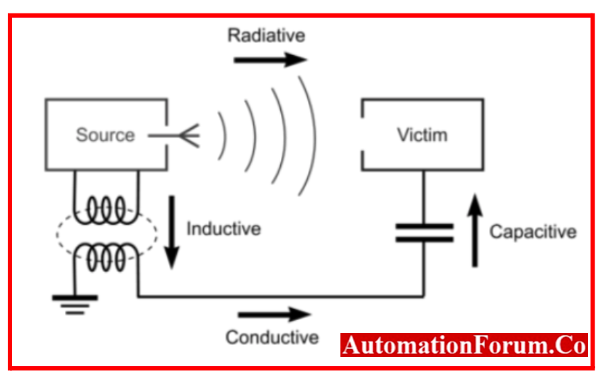
- A source emitter generates the electromagnetic interference (EMI), which is then picked up by a victim through a coupling channel. One or more of the coupling techniques listed below may be used along the coupling path:
- Conduction in Electric current
- Radiation by Electromagnetic fields
- Capacitive coupling in Electric field
- Magnetic Field – inductive coupling
Coupling Mechanism
- The earlier picture depicts the fundamental configuration of the noise source, coupling path, and victim, receptor, or sink.
- However, the source could be a natural occurrence like a lightning strike, electrostatic discharge (ESD), or, in one famous scenario, the Big Bang at the beginning of the Universe. Source and victim are often electronic hardware equipment.
- Conductive, magnetic or inductive, capacitive, and radiative coupling mechanisms are the four fundamental types of electromagnetic interference (EMI) coupling mechanisms.
- One or more of these coupling methods can be used to decompose any coupling path. For instance, the diagram’s lower path includes conductive, capacitive, and inductive modes.
Conductive coupling
- It is when a conducting body, such as a transmission line, wire, cable, PCB trace, or metal enclosure, comes into direct touch with the source and receptor to create the coupling path. conductive patterns
- Conducted noise can also be identified by the way that it manifests on various conductors:
- Noise manifests on two conductors in the same direction when there is a common-mode or common-impedance connection.
- With differential-mode coupling, noise travels along two conductors in the obverse of one another.
Inductive coupling
- Inductive coupling happens when the distance between the source and receiver is only a short one, usually less than a wavelength. When a fluctuating magnetic field exists between two parallel conductors, usually spaced less than a wavelength apart, inductive coupling, also known as magnetic coupling, takes place. This causes a change in voltage along the receiving conductor.
Capacitive coupling
- Capacitive coupling happens when there is a fluctuating electrical field between two nearby conductors that are usually only a few wavelengths apart, causing a change in voltage across the gap.
Radiative coupling
- Radiative coupling, also called as electromagnetic coupling. It occurs when the victim and source are separated by a significant distance, and it is greater than a wavelength. The source emits or radiates an electromagnetic wave that passes through the open space between them and is picked up or received by the victim. The source and victim behave as radio antennas.
Example of EMI problem in Circuit
SMPS Circuit
- SMPS which is one of the most used home appliances suffered from EMI problem at high frequencies.
- A more effective and less expensive power lines filter is implied by the ongoing development of switching power supplies. Nearly all home and commercial applications now use passive power lines filters.
- The suppression of conducted emissions that would otherwise be injected directly onto the power lines is one of the main benefits of putting a filter right at the power entry point.
- Another reason is to reduce power line noise that enters the equipment. “Passive” Line EMI filters eliminate EMI noise.
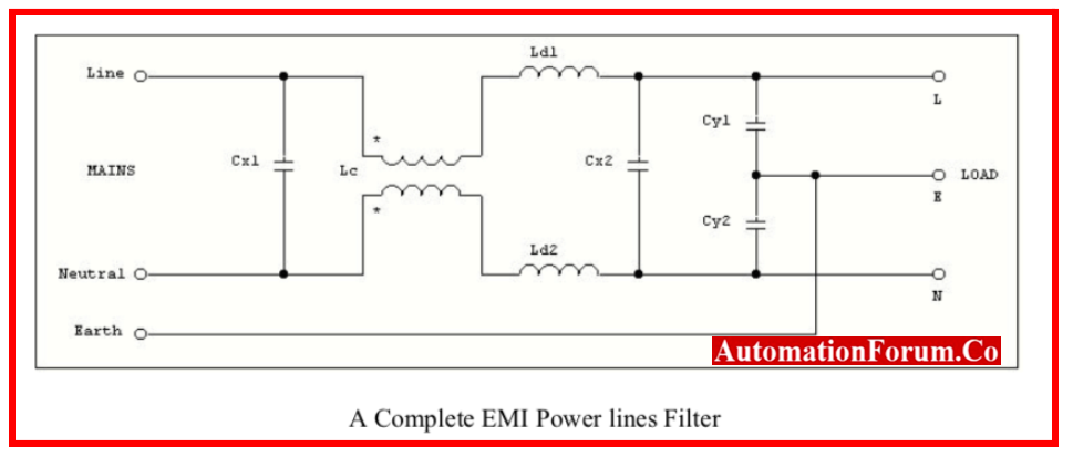
- Nearly all equipment contains power line filters, also known as EMI filters, which have two main functions:
- First, to prevent conducted emissions from the equipment, which would otherwise be fed straight onto the power lines
- Second, to prevent noise from the power lines from entering the equipment. Digital or digitally controlled equipment that is susceptible to the noise frequencies present on the power lines may malfunction as a result of this noise.
The passive EMI filters fulfil both of these requirements thanks to their bidirectional properties. Devices used on the open market have a wider range of regulated frequencies than those used in specialized, isolated installations.
Causes of Electromagnetic interference (EMI) and radio frequency interference (RFI)
Electromagnetic interference (EMI) and radio frequency interference (RFI) in instrumentation systems can be caused by various factors. Here are some common sources and causes of EMI/RFI
Electromagnetic Emissions from Electronic Devices
- Electronic devices themselves can emit electromagnetic radiation, which can interfere with nearby instrumentation systems. This emission can occur due to fast switching signals, poor grounding, inadequate shielding, or improper design of the electronic circuits.
Power Lines and Electrical Sources
- Electrical power lines and sources can generate electromagnetic fields that couple with nearby instrumentation systems. This can happen due to fluctuations in the power supply, voltage transients, power surges, or harmonics generated by non-linear loads
Radio Frequency (RF) Sources
- External RF sources, such as radio transmitters, wireless communication devices, radar systems, and nearby radio or TV stations, can cause interference in instrumentation systems. The RF signals can be received unintentionally by the system’s antennas or cables and disrupt the proper functioning of the equipment.
Electromagnetic Fields from Motors and Transformers
- Electrical motors, transformers, and other high-power equipment can produce strong electromagnetic fields that can induce noise in nearby instrumentation systems. This interference can occur through radiated electromagnetic fields or through conducted coupling via power or signal cables.
Grounding Issues and Ground Loops
- Improper grounding can lead to ground loops, where multiple ground points in a system have different reference potentials. Ground loops can cause unwanted currents to flow through signal or ground connections, resulting in interference.
- Grounding issues can also cause common-mode noise to couple into instrumentation systems.
Crosstalk
- Crosstalk occurs when signals from one circuit or cable unintentionally couple with nearby circuits or cables. This can happen due to inadequate shielding, improper cable routing, or high impedance between signal lines.
Poor Cable Shielding and Routing
- Inadequate shielding or improper routing of cables can make them susceptible to external electromagnetic fields. This can result in noise induction and interference in the instrumentation system.
Environmental Factors
- Environmental factors such as lightning strikes, electromagnetic fields from nearby equipment or power lines, and atmospheric conditions can introduce interference into instrumentation systems.
Improper Filtering and Protection
- Absence or insufficient use of filters, surge protectors, and EMI/RFI suppression components in the system can make it more susceptible to interference.
How to prevent electromagnetic interference (EMI) and radio frequency interference (RFI) in instrumentation systems?
Shielding
- Use shielding materials to enclose sensitive components and cables. Metallic enclosures, such as copper or aluminum, can effectively block electromagnetic waves. Ensure proper grounding of the shields to divert unwanted currents.
Cable Routing
- Separate power cables and signal cables to minimize the coupling of electromagnetic fields. Keep signal cables away from high-power sources and avoid running them parallel to each other for long distances. Use twisted pair or coaxial cables for improved noise rejection.
Grounding
- Establish a proper grounding scheme for all equipment and components. This helps in reducing electrical noise and prevents ground loops. Use a dedicated ground plane or bus for connecting equipment grounds.
Filtering
- Install filters on power lines and signal lines to suppress unwanted noise. Common filters include low-pass filters, high-pass filters, and ferrite beads. They can attenuate high-frequency noise and prevent its propagation.
Proper Layout
- Plan the physical layout of the instrumentation system carefully. Keep sensitive components and circuits away from potential noise sources, such as motors or transformers.
- Use circuit board layout techniques that minimize noise coupling, such as star grounding and avoiding long trace loops.
Compliance with Standards
- Follow relevant EMI/RFI standards and guidelines. For example, the Federal Communications Commission (FCC) provides regulations for emissions from electronic devices. Adhering to these standards ensures that your instrumentation system meets the required electromagnetic compatibility (EMC) levels.
Shielded Enclosures
- If your instrumentation system is housed in a room or cabinet, consider using shielded enclosures to minimize external interference. The enclosure should have conductive walls and doors with proper grounding.
Proper Component Selection
- Choose components that are designed to be immune to EMI/RFI. Look for components with built-in shielding or those that comply with EMC standards. Opt for components with lower emission levels and higher immunity.
EMI/RFI Testing
- Perform EMI/RFI testing on your instrumentation system to identify and mitigate any interference issues. This can include radiated emissions testing, conducted emissions testing, and susceptibility testing.
Education and Training
- Ensure that personnel working with the instrumentation system are trained on EMI/RFI prevention techniques. Proper handling and installation of equipment can significantly reduce the risk of interference.
Frequently asked Questions
What are the methods of EMI protection?
- Line filtering, power supply design, Appropriate layout, and Shielding the enclosure are typical methods to reduce EMI.
- Electrical disturbances can travel through the air or be carried by power lines or electromagnetic, magnetic, or capacitive radiation.
What methods are used to reduce RFI and EMI in the radio?
Filtering, grounding, and shielding are three different ways to assist decrease or eliminate EMI.
What is the best protection against EMI?
- Copper is the most dependable metal for EMI shielding since it is the best at minimizing both magnetic and electrical radiation. Almost any place that requires EMI shielding, such as hospital equipment or simple home computers, can use copper.
How can we protect wires from EMI?
- Use shielding and twisted pair cables to avoid these problems. A cable is shielded to prevent electromagnetic interference (EMI) from other parts of the motion system from damaging it. It is also strongly advised to use a magnetic shield to stop radiation from entering and leaving the cable.
Which media are immune to EMI?
- Optical fiber is EMI-resistant.