
- Introduction
- What is Site Acceptance Test (SAT)?
- What is Site Integration Test (SIT)?
- Complete Industrial Automation Project Testing Timeline
- FAT vs SAT vs SIT Comparison Table
- Detailed Factory Acceptance Test (FAT) Procedure
- Detailed Site Acceptance Test (SAT) Procedure
- Detailed Site Integration Test (SIT) Procedure
- Factory Acceptance Test (FAT) Engineering Checklist
- Site Acceptance Test (SAT) Engineering Checklist
- Site Integration Test (SIT) Engineering Checklist
- Real Industrial Example of FAT vs SAT vs SIT
- Frequently Asked Questions (FAQs) on FAT vs SAT vs SIT
- What is the difference between FAT, SAT, and SIT?
- Why is Factory Acceptance Testing important?
- When should a Site Acceptance Test be performed?
- What is the purpose of a Site Integration Test?
- What documents are required before conducting FAT?
- Who participates in a Factory Acceptance Test?
- What equipment is tested during FAT?
- What is verified during Site Acceptance Testing?
- Can a project skip FAT and perform only SAT?
- What communication protocols are commonly tested during FAT, SAT, and SIT?
- What is a FAT punch list?
- What happens after successful SIT completion?
- Which comes first, FAT or SAT?
- Conclusion: Key Takeaways from FAT, SAT and SIT
Introduction
The successful execution of any industrial automation project requires a planned testing and commissioning approach before allowing the plant to run under live process conditions. For each project, be it a refinery, a petrochemical complex, a power plant, a pharmaceutical facility, a water treatment plant or an LNG terminal the automation system needs to be fully tested that it will operate safely, reliably and according to the approved technical design.
One of the most common causes of delays in plant start-ups may be the misconception that a successful Factory Acceptance Test (FAT) equates to a successful plant start-up. In fact, many automation systems that pass FAT suffer unanticipated problems during installation, communication, integration or commissioning. Completing a Site Acceptance Test (SAT) doesn’t ensure all automation sub-systems will work together correctly when the process starts functioning either. This is why the Site Integration Test (SIT) has become a key milestone in modern industrial projects.
Modern plants are comprised of a plethora of interconnected systems such as Distributed Control Systems (DCS), Programmable Logic Controllers (PLC), Safety Instrumented Systems (SIS), Fire and Gas Systems (FGS), Human Machine Interfaces (HMI), historians, package equipment, Motor Control Centers (MCC), Variable Frequency Drives (VFD) and industrial communication networks. Each subsystem may work fine in isolation, but the entire plant may still fail if these systems are not adequately linked and verified.
FAT, SAT and SIT are three different levels of automated verification each of which serves a specific purpose in the project lifecycle. Before shipping, FAT ensures the control system has been constructed to project specifications by the vendor. SAT validates proper installation and performance of the equipment under actual site conditions at the project site. Before startup, SIT verifies that all the automation systems are communicating and working together as one integrated process.
Understanding the differences between these three acceptance tests can help EPC contractors, system integrators, project engineers, commissioning teams, and plant owners minimize commissioning risks, avoid costly rework, improve safety, and make a smoother transition from construction to commercial operation.
What is Factory Acceptance Test (FAT)?

Purpose of Factory Acceptance Testing
A Factory Acceptance Test (FAT) is the first formal verification of an automation system before it is delivered to the project site. This is done at the equipment manufacturer or system integrator’s location once the panel has been fabricated, the software configured, the hardware assembled and internal quality checks performed.
Never Skip These Critical Control Valve Inspection Activities: Inspection and Test Plan (ITP) for Control Valves
Factory Acceptance Test Objectives
The purpose of FAT is to demonstrate that the PLC, DCS, SIS or SCADA system supplied has been designed, built, programmed and tested in accordance with the approved Functional Design Specification (FDS), Cause and Effect Matrix, I/O list, control philosophy and contract requirements.
Since the actual process equipment is not available during FAT, engineers use signal simulators, software emulators and test benches to simulate field instruments like pressure transmitters, temperature transmitters, flowmeters, control valves, level switches, motor feedback signals and emergency shutdown inputs.
Factory Acceptance Test Objectives
A comprehensive FAT typically verifies:
- Control panel construction and wiring quality
- PLC, DCS, or SIS hardware configuration
- Power supply and redundancy operation
- Analog and digital I/O functionality
- Alarm generation and acknowledgment
- Interlock logic and permissive sequences
- Human Machine Interface graphics
- Historian data collection
- Industrial communication protocols
- Controller redundancy and failover performance
- Software backup and restoration
- Network communication between controllers and operator stations
PLC FAT Example for Industrial Automation Projects
For example, an engineer doing a PLC FAT on a boiler control system will simulate a low drum water level signal to verify that the PLC starts the burner trip sequence, activates alarms at the operator workstation, logs the event in the historian, and implements the shutdown logic as per the approved Cause and Effect Matrix.
Any flaws found during FAT are recorded in a punch list, rectified by the vendor and retested before shipment approval is granted. Finding software issues, hardware flaws, configuration mistakes and documentation discrepancies at the plant is far less expensive than fixing them once the equipment is in the field.
Refer the below link for the Factory Acceptance Test (FAT) Procedure & Checklist for Marshalling Cabinets
What is Site Acceptance Test (SAT)?
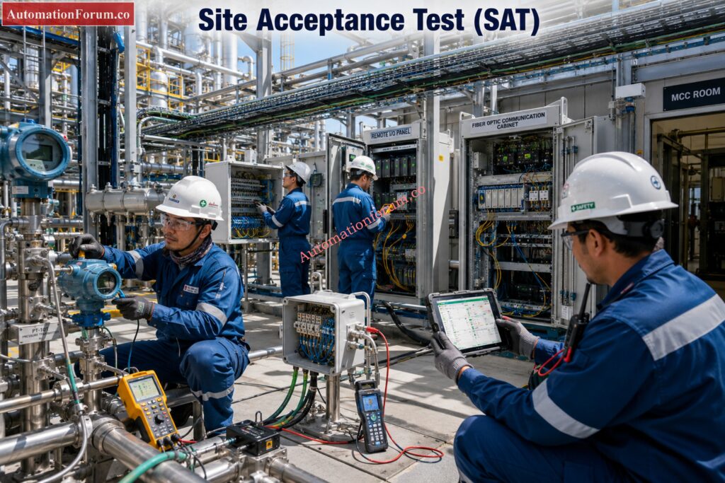
Purpose of Site Acceptance Testing
The Site Acceptance Test (SAT) is performed after the automation system has been delivered to the plant site, installed, wired, powered and prepared for commissioning. FAT ensures the quality of the product at the manufacturer; SAT checks that the equipment is still functioning appropriately after it has been transported and installed.
Site Acceptance Test Objectives
The main goal of SAT is to verify that the installed automation system performs as specified in the real plant environment. FAT is based on simulated signals, SAT tests the system with real field devices, real communication networks, genuine installed power systems and real plant infrastructure in operation.
Avoid Costly MOV Testing Errors Before Site Installation: Motor-Operated Valve (MOV) Factory Acceptance Test (FAT) Procedure
What is Verified During SAT?
Typical SAT activities include:
- Inspection of control panels for transportation damage
- Verification of cable termination and labeling
- Earthing and grounding inspection
- UPS and power supply verification
- PLC and DCS controller health checks
- Remote I/O communication testing
- Instrument loop verification
- Field transmitter calibration confirmation
- Control valve functional testing
- Motor starter feedback verification
- Industrial Ethernet and fiber optic communication checks
- Alarm and event verification
- Operator graphics validation
- Network redundancy testing
SAT Example for Industrial Automation Systems
For example, a pressure transmitter that passed FAT may fail in SAT because of faulty cable polarity, broken field wiring, loose terminal connections or grounding difficulties caused after installation. Before the plant goes in commissioning, various difficulties relating to installation are identified by SAT.
SAT also monitors the connectivity between field devices and higher automation systems. Protocols such as Modbus TCP, PROFINET, EtherNet/IP, FOUNDATION Fieldbus, HART and OPC UA test the integrity of data exchange across the entire plant.
All remaining observations at the conclusion of SAT are documented as punch list items. The project should not be moved to the integrated system testing phase until these issues have been resolved.
SCADA FAT Secrets Every Commissioning Engineer Should Learn Today: Factory Acceptance Test (FAT) Activities for SCADA System: Step-by-Step Checklist
What is Site Integration Test (SIT)?
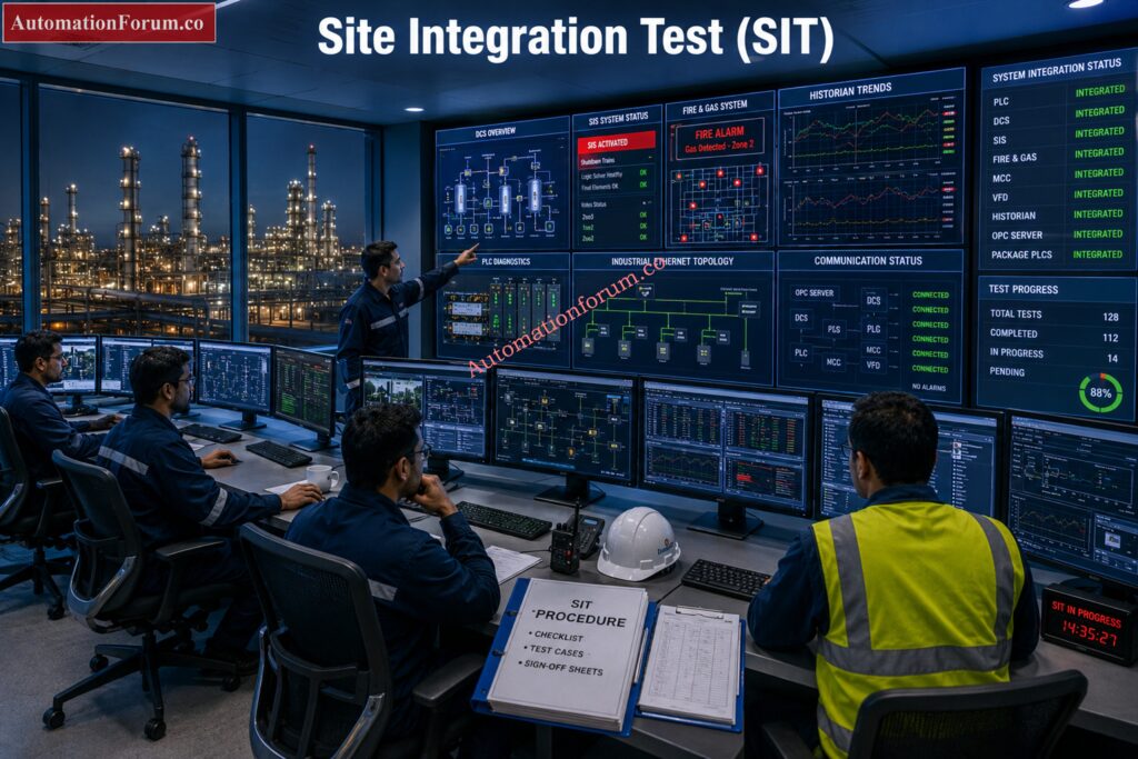
Purpose of Site Integration Testing
A Site Integration Test (SIT) is the final acceptance stage before cold commissioning and plant startup. SIT differs from FAT and SAT in that it tests all automation subsystems working together as one comprehensive process control solution, instead of individual equipment and installed systems.
Site Integration Test Objectives
Modern industrial facilities rarely rely on a single automation platform. Instead, they integrate multiple PLCs, DCS controllers, Safety Instrumented Systems, Fire and Gas Systems, package equipment, Motor Control Centers, Variable Frequency Drives, analyzers, electrical protection systems, historians, asset management systems, and operator workstations supplied by different vendors.
Each subsystem may pass FAT and SAT individually, but when the systems begin to exchange real process data, integration problems often arise.
Instead of individual input and output signals, engineers assess full plant running scenarios in SIT.
What is Verified During SIT?
Typical SIT activities include:
- PLC to PLC communication testing
- PLC to DCS interface verification
- DCS to SIS shutdown communication
- Fire and Gas System integration
- Emergency Shutdown sequence testing
- Motor Control Center communication
- Variable Frequency Drive control verification
- Package equipment interface testing
- Historian data collection validation
- OPC server communication
- Alarm management verification
- Automatic startup sequence testing
- Automatic shutdown sequence testing
- Cause and Effect Matrix verification
- Industrial network redundancy testing
- Controller recovery after communication failures
SIT Example for Integrated Plant Automation
For example a gas detector detects a hydrocarbon leak, then SIT checks that the Fire and Gas System sends the alarm to the DCS, the Safety Instrumented System initiates the Emergency Shutdown sequence, the isolation valves close automatically, the ventilation systems start, warning beacons activate and all the events are correctly logged in the historian. This confirms that every subsystem responds together exactly as defined in the project control philosophy.
If successful, a SIT demonstrates that the complete automation architecture is ready for safe plant start-up.
Critical Control Valve FAT Steps Most Teams Frequently Miss: Factory Acceptance Test (FAT) Procedure for Control Valve
Complete Industrial Automation Project Testing Timeline
The testing sequence in an automation project follows a logical progression, ensuring that problems are identified as early as possible. Completing each stage before moving to the next minimizes commissioning risks and reduces costly site modifications.
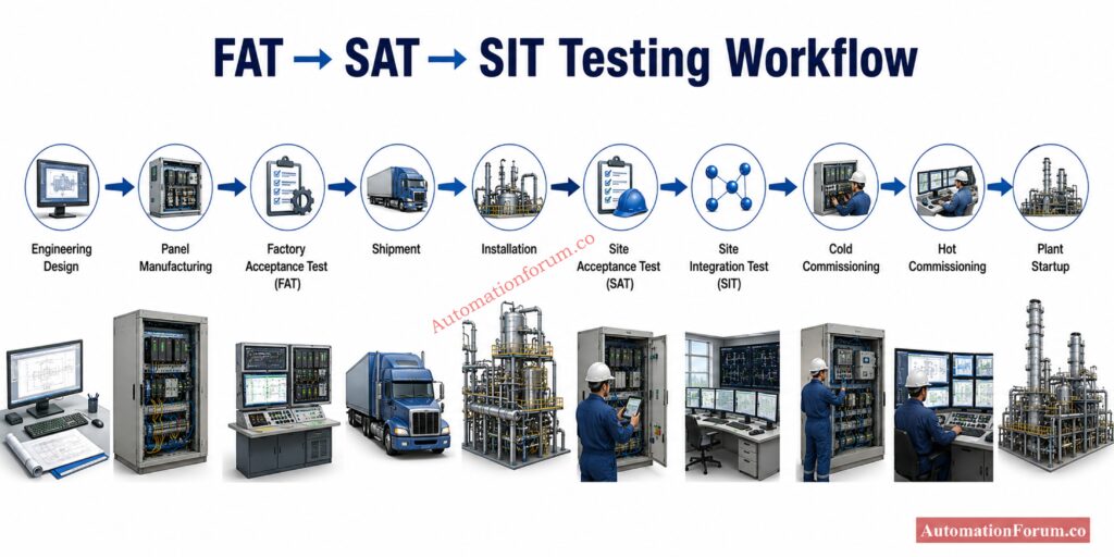
| Project Phase | Purpose |
| Basic and Detailed Engineering | Develop control philosophy, I/O lists, and design documents |
| Panel Fabrication | Build PLC, DCS, SIS, and control panels |
| Software Development | Configure control logic, HMI, alarms, and databases |
| Internal Vendor Testing | Verify hardware and software before customer inspection |
| Factory Acceptance Test (FAT) | Validate the automation system before shipment |
| Shipment to Site | Transport equipment to the project location |
| Installation | Install panels, field devices, cables, and networks |
| Mechanical Completion | Confirm construction activities are complete |
| Loop Checking | Verify every instrument loop from field to control room |
| Site Acceptance Test (SAT) | Validate installed equipment and field wiring |
| Site Integration Test (SIT) | Verify interaction of all automation systems |
| Cold Commissioning | Test systems without introducing process fluids |
| Hot Commissioning | Commission the plant under live operating conditions |
| Performance Testing | Demonstrate design capacity and operational performance |
| Final Handover | Transfer the completed plant to the owner for operation |
FAT vs SAT vs SIT Comparison Table
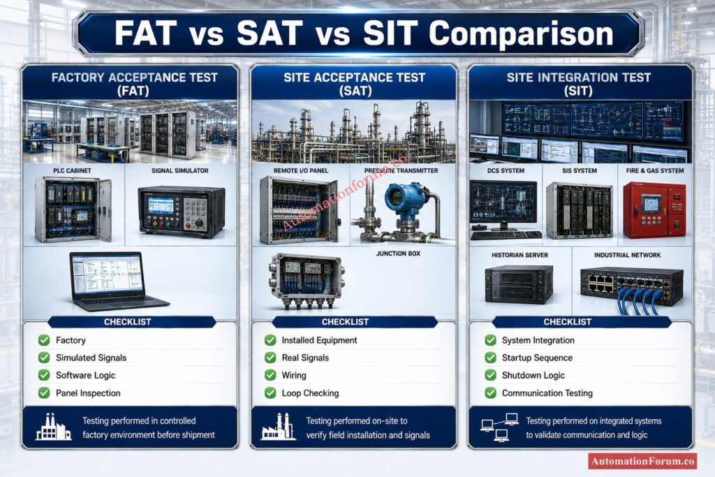
| Parameter | Factory Acceptance Test (FAT) | Site Acceptance Test (SAT) | Site Integration Test (SIT) |
| Primary Objective | Verify that the automation system has been built, configured, and programmed according to the approved design before shipment. | Verify that the installed automation system operates correctly under actual site conditions after installation. | Verify that all automation systems communicate and function together as one integrated plant before startup. |
| Test Location | Conducted at the vendor’s manufacturing facility or system integrator’s workshop. | Conducted at the project site after installation and wiring are complete. | Conducted at the project site after SAT and before commissioning. |
| Project Stage | Performed before equipment is shipped to the customer. | Performed after installation, power-up, and loop checking. | Performed just before cold commissioning and plant startup. |
| Equipment Tested | Individual PLC, DCS, SIS panels, HMIs, servers, network devices, and control panels. | Installed control panels, field instruments, Remote I/O, cables, communication networks, and power systems. | The complete automation system including PLC, DCS, SIS, Fire and Gas, MCC, VFDs, package units, and third-party systems. |
| Signals Used | Simulated analog and digital signals generated using test equipment or software simulators. | Real signals from installed field instruments and process equipment. | Live integrated signals exchanged between all connected automation systems. |
| Communication Testing | Verifies communication within the supplied control system, including controllers, HMIs, and network modules. | Verifies communication between installed field devices, Remote I/O, switches, and control systems. | Verifies end-to-end communication across all plant automation, electrical, and safety systems. |
| Logic Verification | Tests PLC and DCS logic, alarms, interlocks, sequences, and HMI functions using simulated conditions. | Confirms that installed equipment executes the approved logic correctly with actual field devices. | Validates complete operating scenarios such as startup, shutdown, emergency trips, and Cause and Effect sequences. |
| Customer Participation | Vendor engineers, EPC team, client representatives, and quality inspectors witness the tests. | EPC engineers, client representatives, commissioning engineers, and construction teams participate. | Operations personnel, commissioning engineers, EPC team, client, vendors, and safety specialists jointly witness the integrated tests. |
| Main Deliverable | FAT report with completed test records, punch list, and shipment approval. | SAT report confirming installation quality along with resolved or pending punch list items. | SIT report demonstrating successful integrated system performance and readiness for commissioning. |
| Typical Issues Found | Software bugs, incorrect logic, hardware defects, HMI errors, documentation mismatches, and configuration issues. | Wiring mistakes, incorrect cable terminations, calibration errors, communication faults, and installation defects. | Interface mismatches, communication failures between systems, sequence errors, shutdown logic issues, and integration problems. |
| Final Outcome | Customer approves the system for shipment from the factory. | Customer accepts the installed automation system for integrated testing. | Customer confirms the plant is ready to proceed with commissioning and startup. |
| Why It Matters | Prevents expensive design and software corrections after equipment reaches the site. | Ensures installation quality and confirms that every field device functions correctly. | Ensures the entire plant operates safely and reliably as one integrated automation system before introducing live process conditions. |
Detailed Factory Acceptance Test (FAT) Procedure
FAT Engineering Document Review
A successful Factory Acceptance Test follows a process that verifies every part of the automation system before it is shipped. The purpose is to verify that the PLC, DCS or SIS hardware is operational and the software logic, operator interface, communication networks and documentation are per project specifications. It is a lot cheaper to fix problems at the plant when it is being commissioned than to fix problems when the plant is being commissioned.
Verify Every PLC Panel Before It Reaches Your Plant: Factory Acceptance Test (FAT) of a PLC Panel: A Step-by-Step Basic Guide
FAT Hardware Inspection
Then verify the workmanship of the control panels, component labeling, cable routing, terminal identification, power distribution, ventilation, and grounding. Power up and test power supplies, redundant controllers, communication modules, industrial Ethernet switches and UPS systems for steady operation.
FAT Software Logic Testing
Software testing begins after hardware verification. Analog inputs, digital inputs, analog outputs and digital outputs are replicated with calibrated signal generators or software simulators. Engineers confirm proper scaling, engineering units, alert limits, trends, HMI displays. The control philosophy is exercised regularly through automatic sequences, motor start permissives, valve interlocks, shutdown logic and cause and effect functions to confirm that it has been properly applied.
FAT Communication Testing
Communication validation is performed between PLCs, DCS controllers, operator workstations, historians, engineering workstations and third party devices.
FAT Redundancy Testing
Redundancy tests are carried out by disconnecting primary controllers or communication lines to guarantee a smooth handover to standby systems.
Don’t Confuse FAT and SAT During Project Execution: Difference between FAT and SAT
FAT Final Approval and Punch List Closure
Finally, the software backup and restoration operations are validated and the customer representatives analyze the FAT report, verify the closing of the punch list and approve the shipping.
PLC Panel Inspection Secrets Every Maintenance Engineer Should Know: Running Inspection Checklist of PLC Components in Control Panels
Detailed Site Acceptance Test (SAT) Procedure
SAT Site Inspection
The Site Acceptance Test after the equipment installation guarantees that the automation system is still performing well in the real plant. Unlike FAT, SAT validates the system installed with actual field devices and operational infrastructure rather than simulated signals.
SAT Electrical and Power Verification
SAT starts with a full visual assessment of control panels, field junction boxes, marshalling cabinets, cable trays, and instrument installations. Engineers check no damage to equipment in transit and installation is in accordance to approved designs.
Before commissioning of the automation system, the power distribution, UPS systems, earthing, grounding and panel ventilation are verified.
Cable terminations are checked for correct polarity, shielding, gland installation, and terminal numbering.
SAT Cable and Instrument Loop Checking
Fiber optic communication links, industrial Ethernet networks, and Remote I O cabinets are then verified for proper operation.
Loop checking forms a major part of SAT. Each field instrument is calibrated and tested from the sensing element to the control room.
Prevent Flowmeter Failures Using This Proven EPC Inspection Guide: Electromagnetic Flow Meter Inspection and Test Plan (ITP): Complete EPC Guide
SAT Field Device Functional Testing
Pressure transmitters, flowmeters, temperature transmitters, level transmitters, control valves, motor feedback signals, limit switches, and emergency shutdown devices are verified using actual field conditions.
Engineers ensure the receipt of all signals by the PLC or DCS, proper indication of the correct engineering units and trip alarms or interlocks at the set points indicated.
SAT Communication Network Testing
It also confirms the communication between the package systems, PLCs, DCS controllers, Safety Instrumented Systems and operator workstations.
SAT Punch List Closure
All installation issues, wiring faults, configuration mismatches and communications failures found during SAT are logged as punch list items and remedied prior to moving to Site Integration Testing.
Master Every SAT Step Before Starting Control Valve Commissioning: Control Valve Site Acceptance Test (SAT) Procedure – Step-by-Step Field Guide
Detailed Site Integration Test (SIT) Procedure
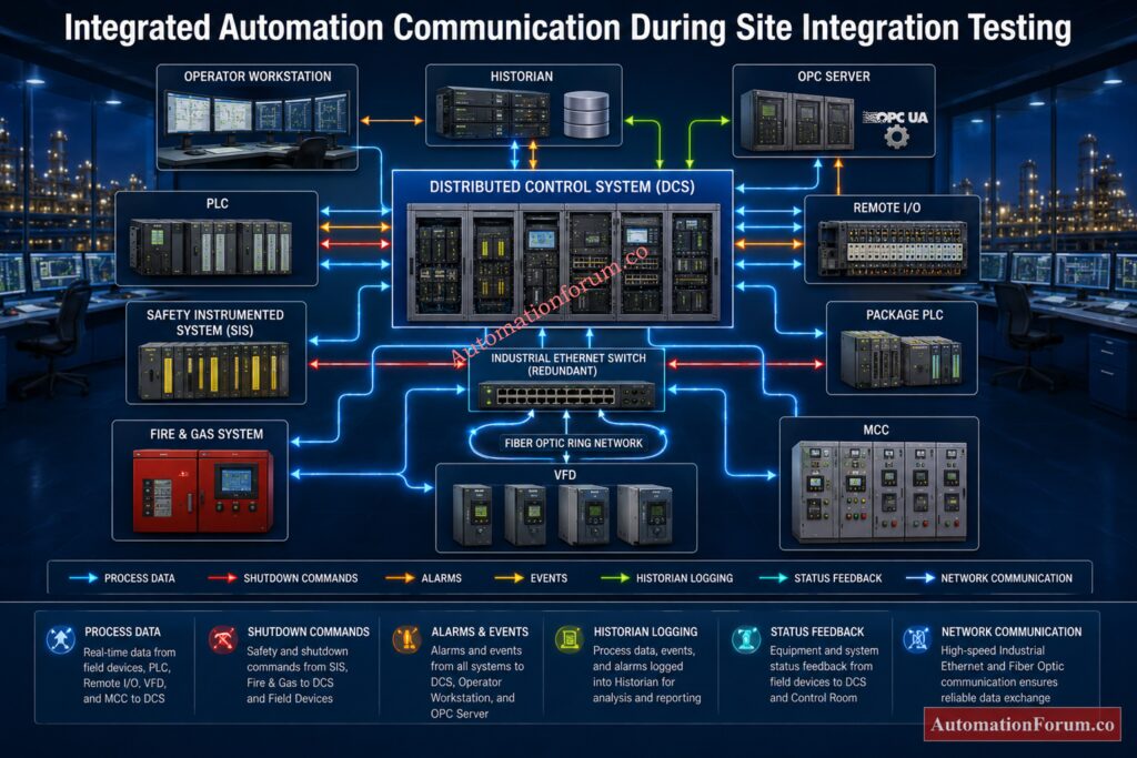
SIT Automation System Integration Testing
The Site Integration Test is the final automation verification before cold commissioning and plant startup. Its purpose is to confirm that every automation subsystem communicates and operates together according to the approved control philosophy.
Unlike FAT and SAT, which operate at the device level, SIT operates at the level of whole operational scenarios. Engineers review the connection between PLCs, DCS controllers, Safety Instrumented Systems, Fire and Gas Systems, Motor Control Centers, Variable Frequency Drives, package equipment, electrical protection systems, historians and operator interfaces.
SIT Communication Interface Verification
Common SIT activities include PLC to PLC communication validation, PLC to DCS interfaces, DCS to SIS Shutdown commands, Fire and Gas integration, Compressor package interfaces, Boiler package controls, Tank gauging systems, Utility packages and Electrical control systems. Alarm management, event logging, historical recording, OPC communication, time synchronization and industrial network redundancy are also validated.
Avoid Cable Tray Installation Mistakes That Cost Thousands: Instrumentation Cable Tray Installation Checklist and Inspection Procedure
SIT Startup and Shutdown Sequence Testing
Integrated startup and shutdown simulations are performed using realistic operating conditions. For example, engineers may simulate a high pressure event on a reactor.
SIT Emergency Shutdown and Safety System Validation
The DCS should generate alarms, the SIS should initiate emergency shutdown logic, motor control centers should stop associated pumps, shutdown valves should close automatically, and the historian should accurately record every event. Operators verify that graphics, trends, and alarm summaries display the correct system response.
SIT Redundancy and Recovery Testing
SIT also includes recovery testing by intentionally disconnecting communication links or restarting controllers to confirm that redundant systems restore normal operation without affecting plant safety.
SIT Final Acceptance Before Commissioning
Only after all integrated scenarios have been successfully completed and punch list items closed is the automation system considered ready for commissioning.
The Temperature Error Every Instrument Engineer Must Prevent: Why Thermocouple Reference Junction Compensation(CJC) is Essential for Accurate Temperature Measurement ?
Factory Acceptance Test (FAT) Engineering Checklist
| Verification Item | Status |
| Engineering documents reviewed | □ |
| Control panel inspection completed | □ |
| PLC and DCS hardware verified | □ |
| Controller redundancy tested | □ |
| Power supplies checked | □ |
| Analog and digital I O tested | □ |
| Alarm and interlock logic verified | □ |
| HMI graphics validated | □ |
| Communication protocols tested | □ |
| Software backup completed | □ |
| FAT punch list closed | □ |
Never Start PLC Commissioning Without This SAT Procedure: Site Acceptance Test (SAT) Procedure for PLC Systems
Site Acceptance Test (SAT) Engineering Checklist
| Verification Item | Status |
| Equipment inspected after shipment | □ |
| Panel installation verified | □ |
| Cable termination checked | □ |
| Earthing and grounding verified | □ |
| UPS operation confirmed | □ |
| Instrument loop checks completed | □ |
| Field device calibration verified | □ |
| Remote I O communication tested | □ |
| Network communication validated | □ |
| SAT punch list closed | □ |
EPC Engineers Should Master Junction Box Grouping Techniques: JB Grouping in Industrial Automation and Instrumentation – Complete Practical Guide for EPC
Site Integration Test (SIT) Engineering Checklist
| Verification Item | Status |
| PLC to DCS communication verified | □ |
| DCS to SIS interface tested | □ |
| Fire and Gas integration completed | □ |
| Emergency Shutdown sequence verified | □ |
| Package equipment communication tested | □ |
| Historian recording validated | □ |
| Alarm management verified | □ |
| Startup and shutdown sequences tested | □ |
| Network redundancy confirmed | □ |
| Final integrated acceptance completed | □ |
Discover Critical SIS Inspection Checks Before Audit Day: Advanced Safety Instrumented System (SIS) Inspection Checklist for IEC 61511 Compliance
Real Industrial Example of FAT vs SAT vs SIT
One LNG export terminal had a Distributed Control System from one vendor, compressor control PLCs from another vendor, a separate Safety Instrumented System, Fire and Gas System, Motor Control Centers, and various packaging skids. All vendors performed Factory Acceptance Testing satisfactorily prior to shipment and all systems passed Site Acceptance Testing following installation.
However, during the Site Integration Test, engineers found a mismatch in communication between the compressor PLC and the DCS. The compressor controller sent suction pressure in bar gauge and the DCS calculations expected bar absolute. The engineering unit system mismatch was the reason of the wrong anti surge calculations during the integrated startup simulations even if both systems were working as expected during FAT and SAT.
The solution to the problem was upgrading the communication mapping and engineering calculations before introducing natural gas into the operation. Had this problem been found at startup, repeated compressor flights could have delayed the commissioning by several days, adding significantly to project expenses. This example shows why SIT is a required verification phase rather than an optional project activity.
Essential Analyzer Inspection Practices Every Plant Engineer Needs: Running Inspection Procedure for Analyzer and Sampling System in Process Industries
Frequently Asked Questions (FAQs) on FAT vs SAT vs SIT
What is the difference between FAT, SAT, and SIT?
Factory Acceptance Test (FAT) is a validation of the automation system at the vendor site before shipping. Site Acceptance Test (SAT) establishes that the installed system functions correctly at the project site, and Site Integration Test (SIT) shows that all automation subsystems can function together as an integrated plant prior to commencement.
Why is Factory Acceptance Testing important?
FAT helps find hardware problems, software bugs, configuration errors and documentation difficulties before shipping equipment. Getting these concerns early lowers commissioning delays, eliminates costly site adjustments, and enhances overall project quality.
When should a Site Acceptance Test be performed?
SAT shall be performed following completion of equipment installation, cable termination, power energization and instrument loop checks. It is generally done prior to cold commissioning and integrated system testing.
What is the purpose of a Site Integration Test?
The main aim of SIT is to validate the communication and interaction between PLCs, DCS, SIS, Fire and Gas Systems, package equipment, Motor Control Centers and other automation systems to ensure safe and reliable operation of the whole plant.
What documents are required before conducting FAT?
Typical documents required for FAT are Functional Design Specification (FDS), Control Philosophy, Cause and Effect Matrix, P and ID, I O List, Logic Diagrams, Instrument Datasheets, Panel Drawings and FAT Test Procedures.
Who participates in a Factory Acceptance Test?
The FAT is normally attended by the system vendor, EPC contractor, client representatives, automation engineers, quality inspectors, project engineers and commissioning engineers to ensure that the automation system meets all the technical and contractual criteria.
What equipment is tested during FAT?
FAT usually covers testing of PLCs, DCS controllers, SIS hardware, SCADA systems, Human Machine Interfaces, control panels, communication networks, power supply, software logic, alarms, interlocks and operator visuals with simulated field signals.
What is verified during Site Acceptance Testing?
SAT tests installation of panels, field wiring, power supply, communication networks, instrument loops, transmitter calibration, control valve operation, alarm functions, interlocks and operator displays using genuine field equipment.
Can a project skip FAT and perform only SAT?
It is not suggested to skip FAT, since problems found after the equipment has arrived at the site are much more expensive and time-consuming to fix than those found during factory testing.
What communication protocols are commonly tested during FAT, SAT, and SIT?
Automation engineers frequently test industrial communication protocols such as Modbus RTU, Modbus TCP, PROFINET, EtherNet/IP, FOUNDATION Fieldbus, PROFIBUS, HART, OPC UA, and Industrial Ethernet during acceptance tests.
What is a FAT punch list?
A FAT punch list is a list of observations, flaws, software changes, hardware issues and documentation revisions found during Factory Acceptance Testing that must be fixed before shipment is approved.
What happens after successful SIT completion?
After successful SIT, project continues for cold commissioning, hot commissioning, performance testing, plant restart and eventually formal handover of automation system to plant owner for commercial operation.
Which comes first, FAT or SAT?
The first step is always a Factory Acceptance Test (FAT) at the vendor’s site before equipment shipment. Once installed, a Site Acceptance Test (SAT) is carried out to ensure that the system is working properly under real site settings.
Eliminate Wiring Defects Before They Become Startup Problems: Instrumentation Cable and Wiring Inspection Procedure: Essential checklist for Project Engineers
Conclusion: Key Takeaways from FAT, SAT and SIT
There are three complementing verification phases that jointly assess if an industrial automation system is really ready for plant startup: Factory Acceptance Test, Site Acceptance Test, and Site Integration Test. Each test is targeted to a distinct phase of project lifecycle and identifies different types of risk prior to the introduction of live process conditions.
FAT is to verify that the automation system has been constructed, programmed and tested to the acceptable specifications before shipment. SAT verifies that the installed equipment, field instruments, communication networks and power systems are operating correctly within the plant environment. SIT gives the ultimate guarantee that all automation subsystems work together as one integrated control system capable of performing normal operations, alarms, interlocks, emergency shutdowns and recovery sequences.
Projects that consistently perform these three acceptance tests benefit less delays in commissioning, lower startup hazards, enhanced operational safety and quicker project handover. “We will provide EPC contractors, system integrators and plant owners with a smoother, safer and more reliable transition from construction to full commercial operation through the use of structured FAT, SAT and SIT procedures, as well as proper documentation and closing out all punch list items prior to commissioning.” The acceptance tests shall be performed such that a plant shall not be regarded ready for startup until all three acceptance tests have been satisfactorily completed, recorded, and formally approved.
Refer the below link for the Checklist for Conducting a Running Inspection of a Control Valve in a Process Area
