
- What is Integrated Factory Acceptance Test?
- Why is IFAT Important in Instrumentation and Control Systems?
- What Systems Are Tested During an Integrated Factory Acceptance Test?
- What is Tested During IFAT?
- What is the Typical IFAT Procedure?
- What Documents Are Required for IFAT?
- How is IFAT Performed in a Process Plant?
- IFAT vs FAT: What is the Difference?
- IFAT vs SIT vs SAT: What is the Difference?
- What are the Benefits of Integrated Factory Acceptance Test?
- What are the Common Problems Found During IFAT?
- How to Prepare for a Successful IFAT?
- What is the Role of an Instrumentation and Control Engineer During IFAT?
- IFAT Checklist for Instrumentation and Control Engineers
- Frequently Asked Questions About IFAT
- Conclusion: Key Role of IFAT in Instrumentation and Control Projects
What is Integrated Factory Acceptance Test?
Integrated Factory Acceptance Test Definition
An Integrated Factory Acceptance Test, commonly called IFAT, is a factory based test used to verify that multiple control and automation systems work together as an integrated system before they are installed at the plant.
Why is IFAT Different From Individual FAT?
Unlike an individual FAT, which mainly checks one system or package, IFAT verifies communication, signal exchange, commands, alarms, interlocks, trips, sequences and operator responses across connected systems.
For example, a process unit may have a DCS, PLC, SIS, ESD system, Fire and Gas System and several package PLCs. IFAT provides an opportunity to test how these systems interact before site installation and commissioning.
Discover The FAT Checks Engineers Cannot Afford To Miss: Factory Acceptance Test (FAT) Procedure & Checklist for Marshalling Cabinets
Why is IFAT Important in Instrumentation and Control Systems?
Why Control System Integration Testing is Required
Modern process plants rarely depend on one automation system. A DCS may exchange information with package PLCs, the SIS, Fire and Gas System, MCC interfaces, analyzers and electrical systems.
An individual FAT can confirm that each system works correctly within its own environment. However, an integration problem may appear only when two or more systems exchange information.
How IFAT Reduces Commissioning Problems
A wrong communication address, incorrect tag mapping or missing status feedback can remain unnoticed during an individual FAT. Finding such problems at site can consume valuable commissioning time because engineers may need to coordinate several vendors while equipment is already installed.
IFAT moves much of this integration testing into the factory environment. Problems can therefore be identified while system specialists, configuration engineers and vendors are available together.
Refer the below link for the Vendor Document for Project Systems Architecture: Complete Engineering Guide for Instrumentation, Automation and Control
What Systems Are Tested During an Integrated Factory Acceptance Test?
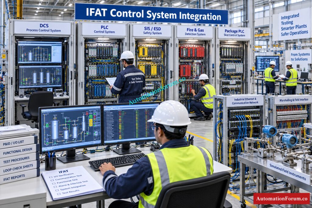
The systems included in an IFAT depend on the project architecture, contractual requirements and approved testing philosophy.
Typical systems include:
- DCS
- PLC
- SIS
- ESD system
- Fire and Gas System
- Package PLC
- SCADA
- MCC interface
- Electrical control systems
- Analyzer systems
- Metering systems
- Third party packaged equipment
- Historian
- Operator workstation
- Engineering workstation
- Alarm and event systems
- Communication gateways
The important point is not simply the number of systems connected. The objective is to verify the required functional interaction between them.
See How DP Transmitter Factory Testing Prevents Costly Failures: Factory Acceptance Test(FAT) Procedure for Differential Pressure(DP) Transmitter
What is Tested During IFAT?

Signal Exchange, I O Verification Control System and Communication Testing
Engineers verify that signals are transferred correctly between systems. This includes digital signals, analog values, commands, status indications and diagnostic information.
Communication protocols such as Modbus, OPC or other project specific interfaces may be involved. Tag names, addresses, data types, scaling and engineering units must match the approved interface documents.
Command and Status Feedback Testing
A command issued from the DCS may need to reach a package PLC and produce the expected equipment response.
The returned running, stopped, available, fault or local mode status must also reach the DCS correctly. IFAT confirms the complete command and feedback path.
Know ESD And PSD Differences Before Designing Shutdown Logic: Marshalling Panel vs Junction Box vs System Cabinet: Complete Guide for Instrumentation and Control Engineers
Alarms, Interlocks and Permissives Testing
Alarm configuration must be checked from the originating condition through to the operator workstation.
Interlocks and permissives are particularly important because a small configuration error can prevent equipment from starting or allow an operation under an incorrect condition.
Trips and Cause and Effect Signal Testing
For SIS, ESD and Fire and Gas applications, engineers simulate appropriate input conditions and verify the resulting safety action.
The test should confirm the complete cause and effect chain, including trip initiation, logic processing, output action, feedback, alarm indication and event recording where applicable.
Choose The Right Cabinet Architecture For Reliable Control Systems: Electromagnetic Flow Meter Inspection and Test Plan (ITP): Complete EPC Guide
Operator Graphics Testing
The operator should see the correct equipment status, alarm and process condition on the workstation.
IFAT can identify incorrect graphics, wrong tag references, missing alarms or misleading status indications before commissioning begins.
Failure and Redundancy Testing
Where applicable, communication failure, controller failure, network failure and redundant path operation should be tested according to the approved project requirements.
Time synchronization, Sequence of Events recording and historian functions may also require verification.
Master The Critical Drawings Every Instrument Engineer Needs: Types of Engineering Drawings and Documents used in Instrumentation
What is the Typical IFAT Procedure?
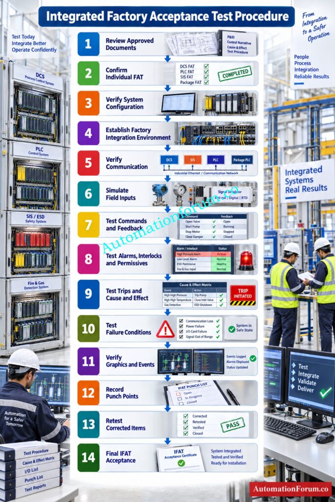
A practical Integrated Factory Acceptance Test can be executed through the following sequence.
Step 1: Review Approved Engineering Documents
Review the Functional Design Specification, System Design Specification, Cause and Effect Matrix, I O list, control narratives, network architecture, communication documents and approved test cases.
Step 2: Confirm Individual FAT Completion
The participating DCS, PLC, SIS and package systems should have completed their required individual FAT activities before integration testing begins.
Step 3: Verify DCS PLC SIS and Package Configuration
Check controller setup, databases, tag mapping, communication settings, visuals and application logic to approved project configuration.
Calculate Intrinsic Safety Parameters Before Hazardous Area Installation: Intrinsic Safety Entity Parameter Calculator for Reliable Hazardous Area Loop Design
Step 4: Establish the Factory Integration Environment
Connect the necessary systems in a controlled production setting. Suitable simulation tools and test interfaces can be employed if actual field equipment is not accessible.
Step 5: Verify Communication Interfaces
Verify the communication lines and correct interchange of all relevant data points. Check addresses, data kinds, scaling, units and update behavior.
Step 6: Simulate Field Inputs and Equipment Status
Produce simulated process values, equipment status indications, Alarms and abnormal circumstances.
Step 7: Test Commands and Status Feedback
Issue operator commands and check that the receiving system processes them successfully and delivers the anticipated status.
Step 8: Test Alarms Interlocks and Permissives
Apply the needed conditions and check the desired control and shutdown response.
Step 9: Test Trips and Cause and Effect
Simulate representative process and safety incidents and validate full reaction across interconnected systems.
Understand Process And Functional Safety Before Critical Decisions: ESD vs PSD: Difference Between Emergency Shutdown System and Process Shutdown System
Step 10: Test Communication and System Failure Conditions
Verify defined communication failures, duplicated pathways, and other applicable abnormal circumstances.
Step 11: Verify Operator Graphics and Events
Check operator indications, alarms, event messages, time-stamps and historical data as appropriate.
Step 12: Record IFAT Punch Points
Step 13: Complete Final IFAT Acceptance
After successful retesting, obtain the required approvals and document the final IFAT status before shipment or site deployment.
Know Which Testing Stage Determines Real Plant Readiness: FAT vs SAT vs SIT: Three Critical Tests That Determine Whether Your Plant Is Truly Ready for Startup
What Documents Are Required for IFAT?
The exact document list depends on the project, but engineers normally require:
- Approved IFAT procedure
- Functional Design Specification
- System Design Specification
- Cause and Effect Matrix
- I O list
- Instrument index
- Control narratives
- Logic diagrams
- P and ID drawings
- System architecture drawings
- Network architecture
- Communication interface documents
- Modbus mapping
- OPC mapping
- Package vendor interface documents
- Alarm and trip lists
- Graphics
- Sequence descriptions
- FAT records
- Approved test cases
- Punch list
- Vendor documentation
Engineers should pay particular attention to interface documents because many IFAT failures originate from differences between vendor databases and the main control system database.
Uncover Essential MOV Testing Steps Before Final Acceptance: Motor-Operated Valve (MOV) Factory Acceptance Test (FAT) Procedure
How is IFAT Performed in a Process Plant?
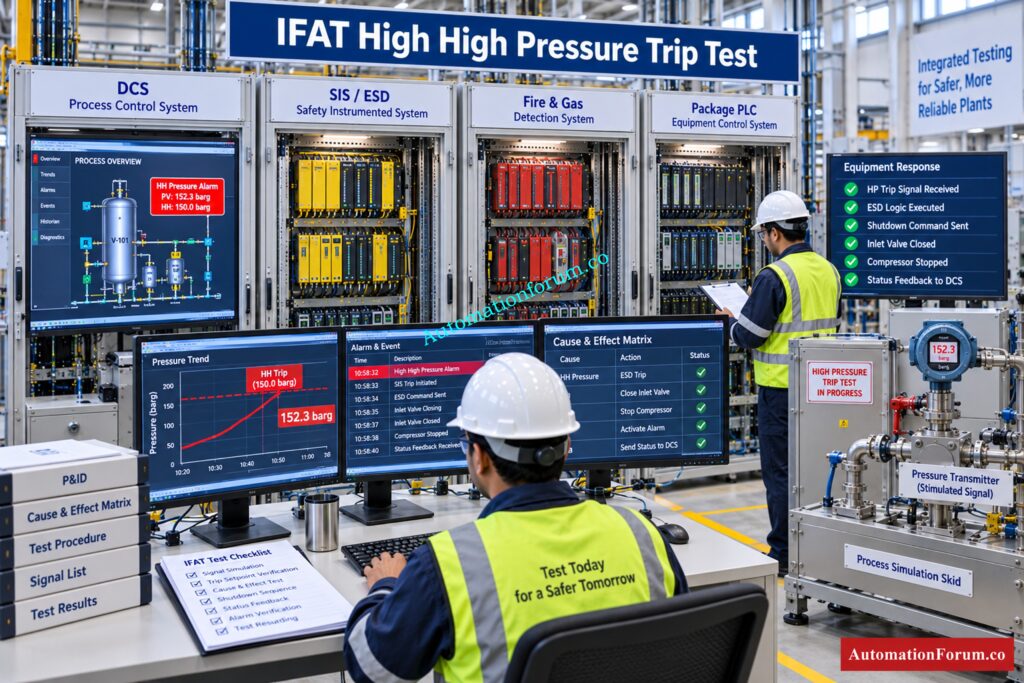
- Consider a process unit where the DCS communicates with a package PLC, SIS and Fire and Gas System.
- During testing, engineers simulate a high high pressure condition in the process.
- The simulated signal reaches the appropriate safety system. The safety logic evaluates the condition and generates the required shutdown command. The affected equipment receives the command and transitions to the desired condition.
- The resulting status is returned to the DCS. The operator workstation displays the appropriate alarm and equipment condition. The event is also recorded where required.
- This single test checks much more than one instrument or controller. It verifies the signal path, communication interface, logic processing, shutdown action, feedback, operator indication and event handling.
- That is the practical value of IFAT.
IFAT vs FAT: What is the Difference?
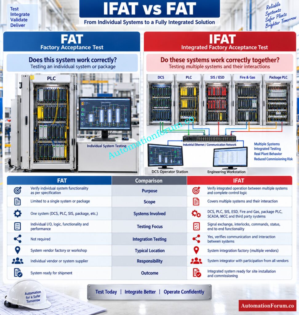
| Area | FAT | IFAT |
| Purpose | Verify an individual system or equipment package | Verify interaction between multiple systems |
| Scope | Usually one system or package | Multiple connected systems |
| Systems involved | DCS, PLC, package or other individual system | DCS, PLC, SIS, ESD, FGS and third party systems |
| Testing focus | Functional and technical requirements | Integration and end to end functionality |
| Typical location | Vendor or system integration facility | Factory integration environment |
| Integration testing | Limited or system specific | Major testing objective |
| Responsibility | Mainly system or package vendor | Multiple vendors, system integrator and project team |
| Outcome | Individual system acceptance | Confidence in integrated system behavior |
An individual FAT answers the question, “Does this system work correctly?”
IFAT goes further and asks, “Do these systems work correctly together?”
Refer the below link for the Site Acceptance Test (SAT) Procedure for PLC Systems
IFAT vs SIT vs SAT: What is the Difference?
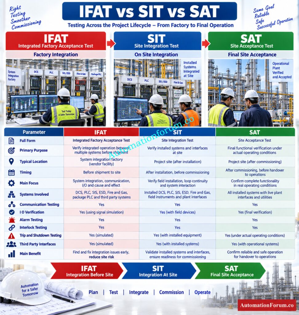
| Parameter | IFAT | SIT | SAT |
| Full Form | Integrated Factory Acceptance Test | Site Integration Test | Site Acceptance Test |
| Primary Purpose | Verify integration and interaction between multiple systems before site installation | Verify integration of installed systems at site | Verify that the installed system meets project functional and acceptance requirements |
| Typical Location | Factory or system integration facility | Project site | Project site |
| Timing | Before shipment and site installation | After system installation and during site commissioning | After installation and required commissioning activities |
| Main Focus | System integration and end to end functionality | Site integration and system interaction | Final acceptance of the installed system |
| Systems Involved | DCS, PLC, SIS, ESD, FGS and third party systems | Installed DCS, PLC, SIS, ESD, FGS and other plant systems | Complete installed control and automation system |
| Communication Testing | Verified before site installation | Verified using installed site networks and interfaces | Verified as part of final system acceptance |
| I O Verification | Mainly through simulated inputs and system interfaces | Verified with installed field interfaces where applicable | Verified under actual site conditions |
| Alarm Testing | Simulated and verified through integrated systems | Verified using installed systems | Verified as part of site acceptance |
| Interlock Testing | Verified using simulation and integrated system logic | Verified using installed equipment and actual interfaces where applicable | Verified against approved functional requirements |
| Trip and Shutdown Testing | Integrated trip logic can be tested using simulated conditions | Site installed trip functions can be verified | Final acceptance of required shutdown functionality |
| Third Party Interfaces | Tested before equipment reaches site | Tested with actual installed interfaces | Confirmed as part of final site acceptance |
| Main Benefit | Finds integration problems before site commissioning | Confirms correct integration after installation | Confirms that the installed system satisfies project requirements |
| Typical Outcome | Integrated system accepted for shipment or site deployment | Site integration verified | System accepted according to project acceptance criteria |
Important: The exact meaning and scope of IFAT, SIT and SAT can vary between projects and organizations. Some projects may use SIT for integration activities that are similar to IFAT. Therefore, instrumentation and control engineers should always follow the project specific testing philosophy, contractual requirements and approved test procedure.
Understand FAT And SAT Before Your Project Advances: Difference between FAT and SAT
What are the Benefits of Integrated Factory Acceptance Test?
- IFAT provides a major advantage by exposing integration problems before site commissioning.
- Incorrect communication mapping can be corrected without waiting for field installation. Interface problems can be resolved while the relevant vendors and system specialists are available.
- It also reduces site troubleshooting because many configuration errors have already been identified and corrected.
- Testing DCS, PLC, SIS and third party interfaces together improves confidence in the overall automation architecture. You can also check the operator graphics, alarms and shutdown answers before deploying the system.
- This early verification can decrease engineering rework, and assist avoid unnecessary delays to commissioning on major projects.
See How Cause And Effect Logic Prevents Dangerous Failures: Cause and Effect Drawings
What are the Common Problems Found During IFAT?
Experienced engineers commonly encounter problems such as:
- Incorrect communication mapping
- Wrong tag mapping
- Incorrect scaling
- Wrong engineering units
- Incorrect alarm configuration
- Missing status feedback
- Incorrect command logic
- Wrong permissive
- Incorrect interlock
- Communication timeout
- Network redundancy problems
- Incorrect PLC to DCS data mapping
- Incorrect SIS interface
- Wrong graphics indication
- Incorrect Sequence of Events timestamp
- Incorrect communication failure response
- Third party interface mismatch
These issues may appear minor during factory testing, but they can become significant commissioning problems when discovered after equipment installation.
How to Prepare for a Successful IFAT?
- Project engineers should prepare the integration test well before the scheduled test date.
- Freeze the appropriate configuration prior to testing and verify that individual FAT activities are complete. Review all interface documents and check tag mapping between systems.
- Test not only typical operational circumstances but realistic test situations. Include startup conditions, shutdown conditions, alarms, interlocks, permissives, trips and communication failures where applicable.
- Each vendor should understand its testing responsibility. Acceptance criteria should be agreed before execution.
- Maintain a live punch list and retest every corrected item. Final acceptance should be based on documented evidence rather than verbal confirmation.
Check Every PLC Panel Function Before Site Shipment: Factory Acceptance Test (FAT) of a PLC Panel: A Step-by-Step Basic Guide
What is the Role of an Instrumentation and Control Engineer During IFAT?
- An Instrumentation and Control Engineer plays an important role in ensuring that the integrated system behaves as intended.
- The engineer should review I O mapping, verify instrument signals, check control logic and confirm alarm behavior. Cause and Effect functions, permissives, interlocks and shutdown signals should be tested against the approved engineering documents.
- The engineer should also verify graphics, communication interfaces and equipment status indications.
- During vendor testing, deviations must be recorded clearly. A useful punch point should identify the affected tag, expected behavior, actual behavior and required corrective action.
- The engineer should then follow the item through correction, retesting and final closure.
Fix PROFIBUS Failures Before They Disrupt Plant Commissioning: PROFIBUS Communication Failure Step by Step Diagnosis
IFAT Checklist for Instrumentation and Control Engineers
Before starting IFAT, confirm:
- Documents are approved
- System configuration is ready
- Individual FAT is completed
- Communication links are ready
- I O mapping is verified
- Tag database is verified
- Alarm configuration is verified
- Cause and Effect is verified
- Interlocks are verified
- Permissives are verified
- Trip functions are verified
- Graphics are verified
- Third party interfaces are verified
- Redundancy is verified where applicable
- Failure scenarios are prepared
- Test results are recorded
- Punch list is updated
- Retesting is completed
- Final acceptance is documented
Choose ESD Signals Correctly Before Safety Logic Implementation: How are ESD Signals Selected? Complete ESD Signal Selection Guide
Frequently Asked Questions About IFAT
What is an Integrated Factory Acceptance Test?
IFAT is a factory based integration test that verifies communication and functional interaction between multiple control, safety and third party systems before site installation.
It confirms that integrated functions, signals, commands, alarms and system interfaces work correctly before commissioning.
Why is IFAT required?
IFAT detects integration issues early, reducing troubleshooting at the site, engineering rework, commissioning risk and project delays.
This gives the chance to verify the integrated system functionality in controlled production circumstances.
What is the difference between FAT and IFAT?
FAT generally verifies an individual system, equipment package or subsystem against approved requirements.
IFAT focuses on communication and functional interaction between multiple integrated systems.
What is tested during IFAT?
IFAT can test communication, signal mapping, commands, feedback, alarms, interlocks, permissives, trips, Cause and Effect, sequences, graphics and redundancy.
Failure responses and communication recovery may also be verified according to the approved IFAT procedure.
Is IFAT performed before SAT?
Normally, IFAT is performed before site acceptance activities and before final commissioning at site.
This helps to uncover integration problems before equipment is deployed and tested under actual site conditions.
Build A Strong Shutdown Strategy Before Plant Commissioning: Shutdown Philosophy: Engineering Documentation for Process Safety and Emergency Shutdown Systems
Who participates in an IFAT?
DCS, PLC, SIS, package system and third party vendors may participate along with system integrators and project engineers.
Commissioning engineers, client representatives and other responsible technical personnel may also participate.
Follow DCS FAT Checks Before Moving Toward Site Testing: Factory Acceptance Test Procedure for Distributed Control System DCS
What documents are required for IFAT?
Typical documents include the IFAT procedure, I O list, Cause and Effect Matrix, control narratives, system architecture and communication mapping.
Test cases, graphics, approved drawings, vendor documents and individual FAT records may also be required.
What is a Factory Acceptance Test?
A Factory Acceptance Test or FAT verifies that a system, package or equipment meets approved technical and functional requirements before shipment.
It normally covers hardware, software, control functions, alarms, interlocks and other specified acceptance criteria.
What does IFAT mean?
IFAT stands for Integrated Factory Acceptance Test and verifies the integration of multiple systems before site installation and commissioning.
It typically focuses on communication, signal exchange and functional interaction between interconnected systems.
What is the difference between FAT and UAT?
UAT determines whether the final system meets user acceptance and business needs.
What are the four types of acceptance testing?
Terminology varies from project to project but common stages of acceptance testing are FAT, IFAT, SAT and UAT.
They test system functionality, integration, site operation and user approval in an incremental manner.
What is the full form of FAT?
FAT is short for Factory Acceptance Test and is generally carried out before the equipment or systems are sent to site.
It demonstrates that certain technical and functional requirements have been satisfactorily tested.
How is QA different from UAT?
Quality Assurance is the methods and controls used to keep quality in and defects out of the project.
The purpose of User Acceptance Testing is to determine whether the supplied system satisfies the operational needs of the user.
What is SAT vs FAT?
FAT is performed at the factory to verify equipment or system functionality before shipment to the project site.
SAT is performed at site to verify installation, configuration, integration and operation under actual site conditions.
Verify SIL Performance Before Approving Safety System Design: SIL Verification Report (Safety Integrity Level Verification Report)
Conclusion: Key Role of IFAT in Instrumentation and Control Projects
A successful Integrated Factory Acceptance Test is not simply a larger FAT. Its real purpose is to prove that different automation and safety systems can operate together as one integrated control environment.
For instrumentation and control engineers, IFAT provides an opportunity to verify the complete signal path before reaching site. DCS commands, PLC responses, SIS trips, Fire and Gas alarms, package interfaces, communication links and operator indications can all be tested in a controlled environment.
When properly planned and executed, IFAT gives the project team much greater confidence that the integrated system is ready for installation, commissioning and eventual plant operation.
Refer the below link for the Factory Acceptance Test (FAT) Procedure for Control Valve
