Instrument air compressors are the most important part of process industries. They provide clean, dry, and dependable compressed air to important control and instrumentation systems. If the compressor’s instrumentation or control logic fails, it might stop the plant from working, which can cause downtime or safety issues. This advanced quiz is for experienced instrumentation and control engineers who want to test their knowledge of compressor sequencing logic, interlocks, monitoring instruments, maintenance plans, and control systems like ES100 panels. Each question tests your knowledge of real-life situations, your ability to solve problems, and the standards of your field. Take the quiz to prove your knowledge and find out where you can improve your skills.
Programmable logic controllers are used by industrial automation engineers, therefore they need to know how timers work. In Schneider EcoStruxure Machine Expert, choosing between TON (Timer On-Delay) and RTO (Retentive Timer On-Delay) can have a big effect on how well the system works, how reliable it is, and how much maintenance it needs.
One of the first things we notice when we enter the world of industrial automation is how important timing is. Try to picture running a conveyor system, a packaging line, or a chemical mixing tank without knowing how long it will take. Motors would start up suddenly, pumps would hit one other, alarms would go off at random times, and the whole thing would feel like a mess.
This detailed article looks at both types of timers by showing how to use them in a real-world conveyor motor control system, showing how they work in real life and how they affect industrial processes.
Timer instructions are the most important part of sequential control systems in industrial automation. They give machines accurate time-based actions that are necessary for coordinating them, following safety rules, and keeping processes consistent.
TON (Timer On-Delay)
The standard timing function in most PLC applications is TON (Timer On-Delay). The timer starts counting up to its preset value when the input condition is met. The output becomes active once it reaches the desired level. The most important thing about TON timers is that they don’t keep track of time. If the input signal is interrupted, the accumulated time goes back to zero right away.
RTO (Retentive Timer On-Delay)
RTO (Retentive Timer On-Delay) is a more advanced feature since it keeps track of time even when the input conditions change or the power goes out. Because they can keep time even when the process is interrupted, RTO timers are great for applications that need timing to stay consistent.
You can think of timers as the PLC’s built-in clock. They assist us:
Delay operations, such waiting five seconds before turning on a fan.
Extend outputs, such keeping a buzzer going for 10 seconds after an alarm goes off.
Limit actions, such just running an engine for 30 seconds before turning it off.
Without timers, developers would have to use external hardware relays or do things by hand. Timers included into the PLC give us accuracy, reproducibility, and flexibility.
Most PLC systems have three types of timers that are common:
TON (On-Delay Timer) waits for a predetermined amount of time after input turns ON before turning on output.
TOF, or Off-Delay Timer, keeps the output on for a defined amount of time even after the input goes off.
RTO (Retentive On-Delay Timer) works like TON, but it keeps track of how long has passed even if the input shuts off or the power goes out.
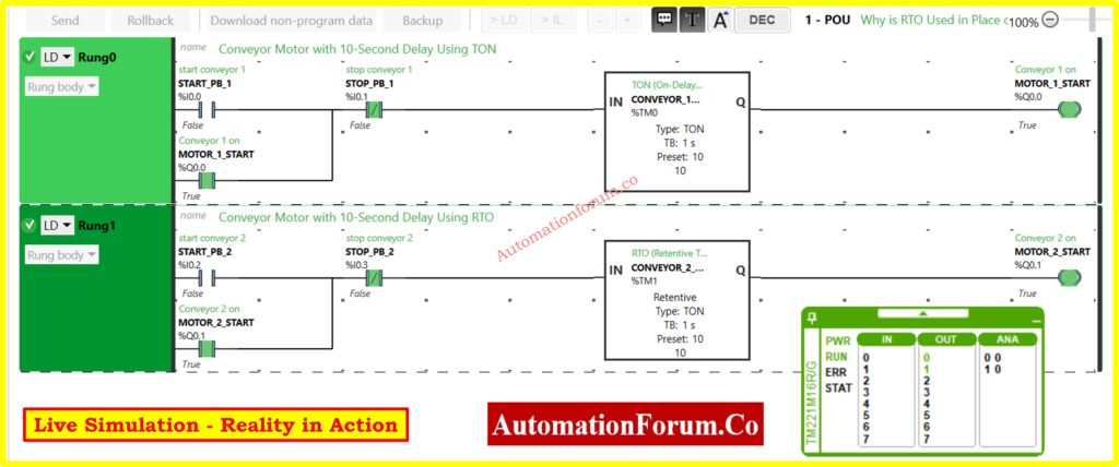
Ladder Logic Implementation in EcoStruxure Machine Expert
The practical implementation shows two conveyor systems that run at the same time but use different types of timers. This side-by-side comparison shows that TON and RTO clocks work in quite different ways.
Rung 0: TON Timer Configuration
The first rung uses the TON timer to add a typical delay to the start of the conveyor:
Input Logic: START_PB_1 (%I0.0) sends the signal to start.
Safety Interlock: STOP_PB_1 (%I0.1) makes a normally closed stop control for the safety interlock.
Timer Block: %TM0 configured as TON with 10-second preset
The same circuit configuration makes it possible to fairly compare how timers work..
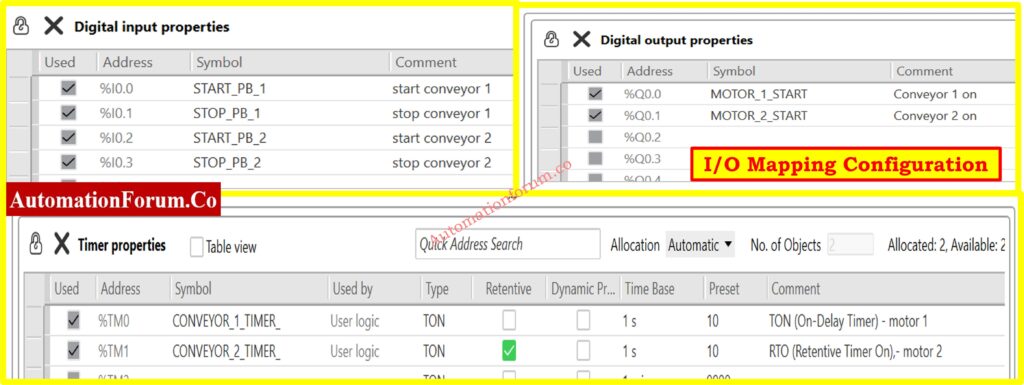
System Configuration and I/O Mapping
Addressing and property settings in the right system setup show the important distinctions between timer implementations.
I/O Address Assignment
The organized I/O allocation makes it easy to find and fix problems:
Digital Inputs:
%I0.0 (START_PB_1): Conveyor 1 start pushbutton
%I0.1 (STOP_PB_1): Conveyor 1 stop pushbutton
%I0.2 (START_PB_2): Conveyor 2 start pushbutton
%I0.3 (STOP_PB_2): Conveyor 2 stop pushbutton
Digital Outputs:
%Q0.0 (MOTOR_1_START): Conveyor 1 motor starter
%Q0.1 (MOTOR_2_START): Conveyor 2 motor starter
Timer Properties Configuration
The timer configuration table shows the main difference between the two implementations:
%TM0 (CONVEYOR_1_TIMER): Standard TON configuration, non-retentive
%TM1 (CONVEYOR_2_TIMER): TON with retentive checkbox enabled
The retentive checkbox changes the way ordinary TON works into RTO functionality, which makes the system behave very differently when there is an interruption.
The simulation environment gives engineers real-time access to the condition of the system and the functioning of the timer. This lets them see how behavior changes in different operational situations.
Simulation Capabilities
The runtime display has a lot of monitoring options:
Timer Values: The total time for both timer instances is shown in real time.
I/O Status: Shows the live input/output condition with true/false values
System Diagnostics: PWR, RUN, ERR, and STAT status indicators
Timer Details: Preset values, elapsed time, and completion status
This level of visibility makes it easy to check for discrepancies in timer behavior right away and fix operational problems.
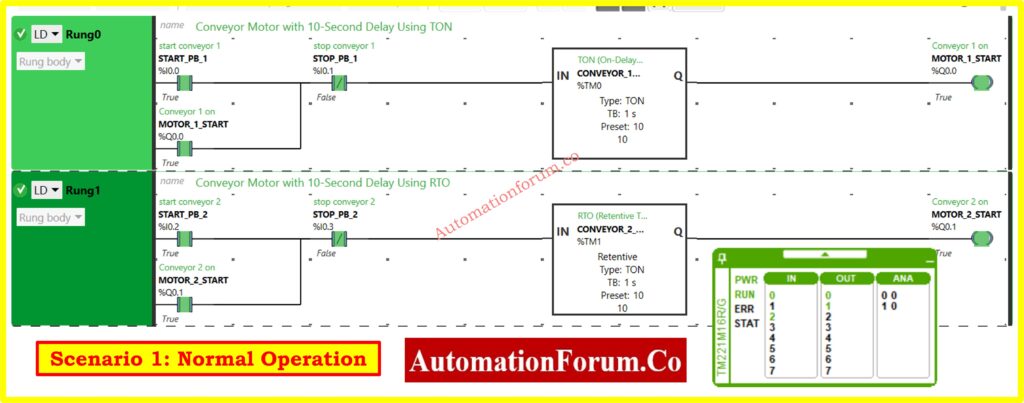
When everything is normal and there are no interruptions, both the TON and RTO timers work in the same way, which makes their main distinctions less clear.
Operational Sequence
The regular order of operations goes like this:
Start Phase: Operators hit the start buttons for their machines
Timing Phase: Both timers start counting from zero up to the 10-second setting.
Completion Phase: After 10 seconds, the timer outputs turn on at the same time.
Motor Operation: Both conveyor motors start at the same time.
Status Indication
The simulation display confirms normal operation through status indicators:
Both start buttons show that they are working.
Both stop buttons say “False.”
Both clocks reach the predetermined value of 10 seconds.
Both motor outputs turn on to True condition.
his instance shows that choosing a timer type doesn’t matter while things are running smoothly.
Safety-Critical Systems: Applications that need to be able to start over from scratch after any interruption make sure that the execution is delayed until all safety checks are done.
Simple Process Delays:Delays in starting up basic equipment where timed restart is okay or preferred.
Cost-Sensitive Implementations: Systems that put a high value on using as little memory as possible and making programming easy.
Regulatory Compliance: When safety regulations say that full timing cycles must be used.
Let’s pretend to be a plant engineer now. Why would you choose an RTO over a TON?
Process Continuity
You want your conveyors, pumps, or mixers to start up again without any problems if the power goes off. When you start everything anew, it can cause backlogs, jams, or wasted goods.
Time and Energy Savings
In high-speed manufacturing, every second matters. RTO saves energy and time by minimizing delays that aren’t necessary.
Improved Safety
In some systems, it might not be safe to restart a timer from zero. If heaters or ovens start a full cycle again for no reason, they could overheat materials or break equipment.
Compliance in Regulated Industries
Accuracy is important in the pharmaceutical, chemical, and food industries. You can’t afford to mix a batch for an extra 10 seconds after a flicker if it needs exactly 10 seconds of mixing. RTO makes sure that things are always the same.
Common Pitfalls with RTO
Of course, having a lot of authority means you have to be responsible. These are common blunders that new engineers make:
Forgetting the Reset Instruction
You have to reset RTOs on purpose for them to clear. If you forget, timers could keep old values forever.
Incorrect Reset Logic
Reset connected to the wrong input? The timer never clears, which makes things act strangely.
Using RTO Everywhere
Some apps don’t need RAM that can be kept. RTO makes logic more complicated than it needs to be.
Overlooking Documentation
Because RTO works differently, engineers need to make sure that the purpose of the timer is obvious in the program comments.
Best Practices for Engineers
Here is a short list of things to remember while utilizing timers:
Use TON for simple jobs like delays, buzzers, alarms, lighting, or things that aren’t very important.
Use RTO when you need to keep things going.
Always provide a reset pushbutton (like %I0.1) so that operators can control things by hand.
During commissioning, pretend that the power goes out. Don’t wait for the plant to deal with it in person.
Give unambiguous tag names, such %TM1 = Conveyor_Start_RTO, instead than just %TM1.
Teach operators why one conveyor starts up quickly and the other takes longer to do so.
TON vs RTO – Side by Side Comparison
Here’s a quick comparison recap:
Feature
TON Timer
RTO Timer
Accumulator Behavior
Resets to 0 on input OFF/power loss
Retains elapsed time until reset
Power Loss Recovery
Always restarts from 0
Resumes from last stored value
Reset Required?
No
Yes (explicit rung)
Best Suited For
Simple delays, alarms, interlocks
Critical processes needing continuity
Example Application
Motor start delay, buzzer alarms
Conveyor sequencing, batch processing
Choosing the Right Timer for Your PLC Application
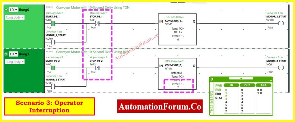
A side-by-side comparison of TON and RTO timers using a real conveyor shows that they work in quite different ways, which has a big effect on how efficient and reliable the system is.
Both types of timers work the same way when they are running, but when you press the stop button, they operate differently. This shows why it’s important to choose the right timer for industrial automation applications.
Choose TON timers for applications that need guaranteed fresh start behavior, simple delay actions where a restart is okay, and implementations that are sensitive to cost and want programming to be as easy as possible.
Choose RTO timers for applications that are crucial to production and need timing continuity, high-frequency start/stop operations, and manufacturing environments where delays in production have a direct effect on operational efficiency.
Engineers may make smart choices that improve both system dependability and production performance in industrial automation applications when they know these basic differences. Choosing the right timer and following the right configuration and maintenance procedures will make sure that it works reliably while also fulfilling the needs of the application and the priorities of the operation.
Test your knowledge with our PLC Timers Quiz
Refer the below link to Test your knowledge with our PLC Timers Quiz
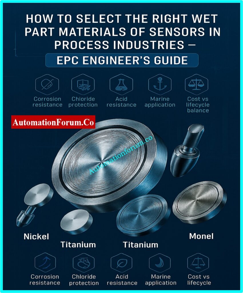
In instrumentation engineering, a sensor is only as good as the material that makes up its wet parts, which are the sections that come into touch with process fluids. Choosing the right wet part material is not just a matter of following the rules for Instrumentation EPC (Engineering, Procurement, and Construction) engineers; it is also a strategic design choice.
If you choose the wrong material, your sensors may fail early, corrode and leak, give you wrong readings, and cost you a lot of time and money. On the other hand, making the appropriate option can make instruments last longer, lower maintenance costs, keep people safe, and make sure that measurements are always accurate throughout the life cycle of a plant.
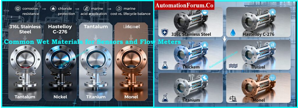
The following article goes into great detail about the most common wet materials used for sensors and flow meters, such as 316L stainless steel, Hastelloy C-276, tantalum, nickel, titanium, and Monel. It also discusses how to choose the best one for your needs.
Why Wet Material Selection Matters in Process Instrumentation
Instrumentation in process industries encounters a diverse array of challenges:
Refineries and chemical plants use corrosive chemicals all the time. Sensors are always in contact with acids, solvents, and by-products that can quickly damage materials that aren’t right for them.
Seawater and brine systems with high levels of chloride are frequent in desalination, offshore oil and gas, and cooling water systems, where stainless steels commonly fail.
Fertilizer and pulp & paper mills have strong acids and alkalis, which makes them very demanding places that need specific coatings or exotic alloys.
Food-grade sanitary standards for dairy and drinks mean that materials must not only be resistant to corrosion but also meet FDA and 3A standards.
In power plants, there are cycles of high pressure and high temperature. These cycles can speed up material fatigue and stress corrosion cracking.
When wet part materials can’t handle these conditions, the results are unsafe:
Corrosion or pitting that causes leaks tiny pits can expand and create major failures.
Stress corrosion cracking (SCC) happens when the pressure and temperature change quickly and without warning. This makes instruments less reliable.
Loss of calibration and drift in measurement accuracy—chemical attacks modify how sensors respond, which can lead to inappropriate actions in process control.
Unexpected downtime and replacement costs—every time you have to replace an instrument that you didn’t plan to adds time and money to the operation.
Process safety risks, especially in dangerous or flammable service, like in oil and gas or chemical facilities, where a material failure can lead to serious safety problems.
Wet portions are the parts of a sensor or transmitter that come into direct contact with the process media in process instrumentation. Choosing the right materials is very important because it influences the sensor’s dependability, resistance to corrosion, and overall cost over its lifetime. A bad choice can cause a lot of problems, downtime, and safety risks.
Diaphragms in pressure transmitters, electrodes in pH probes, and lining materials in flowmeters are all common examples of wet parts. EPC engineers need to be very careful when choosing wet parts during the design stage to make sure that the process will be available for a long time and that it meets industry requirements.
Let’s explore at the six most common wet materials utilized in designing instruments, as well as their pros and cons and common uses.
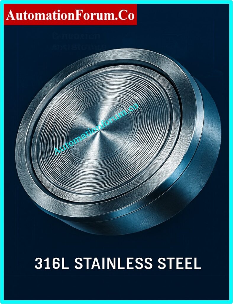
1. 316L Stainless Steel – The Workhorse of Instrumentation
Key Properties:
Resistant to corrosion in mild chemicals and water applications
Strong and easy to weld
Affordable and easy to find
Applications:
Uses: Sensors that can be used for many things, like water purification, HVAC, and food processing
Flow meters for clean service (potable water and non-aggressive substances)
In places with a lot of chloride, like seawater or brine, it is easy to get pitting corrosion.
Not very resistant to strong acids like HCl and H2SO4
EPC Engineer’s Note: Unless your process fluid is very corrosive, choose 316L as the default. Check the levels of chloride again before giving your approval.
Step-By-Step Guide for EPC Design Engineers: Thermowell Selection Procedure – Refer the below link
2. Hastelloy C-276 – The Chemical Industry Champion
Key Properties:
Nickel-molybdenum-chromium alloy that has tungsten in it
Very good at resisting both oxidizing and reducing agents
Very resistant to hydrochloric acid, chlorine gas, moist chlorine, and hot, dirty media
Applications:
Chemical plants (for chlorination, bleaching, and pickling)
Power plants use flue-gas desulfurization (FGD) systems.
Refinery conditions that are harsh and have mixed acids
Limitations:
Costs a lot more than stainless steel
Harder to weld and machine
EPC Engineer’s Note: If you’re not sure about aggressive chemical mixtures, Hastelloy C-276 is the safest alternative, although it will cost a lot to get.
3. Tantalum – The Super Metal
Key Properties:
Almost immune to strong acids, including HCl and H2SO4 at high concentrations
Works very well in hot, corrosive acid service
Long service life even when there is a lot of corrosion stress
Applications:
Specialty chemical plants that deal with acid digestion processes
The semiconductor and drug industries
Hydrochloric acid storage and sulfuric acid towers
Limitations:
Very expensive, hence it can only be used in a few specific situations.
Needs special welding and machining skills
Note from the EPC Engineer: Only use Tantalum if no other material can survive. Before making a recommendation, always do a life-cycle cost analysis.
4. Nickel – The Alkali Specialist
Key Properties:
It is very resistant to caustic soda (NaOH) and alkaline solutions.
Can handle neutral and decreasing conditions
Relatively lower cost compared to exotic alloys
Applications:
Plants that make caustic soda
Bleaching with alkaline in the pulp and paper industry
Making batteries and electroplating
Limitations:
It doesn’t stand up to powerful oxidizers like nitric acid.
Compared to stainless steel, it has moderate mechanical strength.
EPC Engineer’s Note: If you need something that can resist caustic substances, use nickel. Don’t go to places that are oxidizing.
5. Titanium – The Marine & Seawater Specialist
Key Properties:
Very good at resisting chlorine and saltwater attacks
Lightweight, strong, and safe for living things
Creates a stable, passive oxide film to keep things safe
Applications:
Desalination plants and oil and gas platforms in the ocean
Cooling circuits for power plants that use seawater
Uses in medicine and aerospace
Limitations:
Costs more than stainless steel
Needs careful welding and making methods
EPC Engineer’s Note: Titanium is the best material for seawater and high-chloride brine. It is better than 316L or Monel.
6. Monel – The Nickel-Copper Alloy
Key Properties:
It is very resistant to hydrofluoric acid, saltwater, and alkaline environments.
Strong mechanical qualities over a wide range of temperatures
Strong against cracking from stress corrosion
Applications:
Marine uses include propeller shafts and seawater valves.
Chemical plants use hydrofluoric acid for service.
Brine systems and heat exchangers
Limitations:
More expensive than stainless steel but less expensive than Hastelloy or Tantalum
Not very resistant to strong oxidizing agents
EPC Engineer’s Note: When working with HF acid or seawater, think about using Monel instead of Titanium, which might be too strong.
Sometimes instead of using expensive exotic alloys, EPC engineers prefer protective coatings or linings:
PTFE (Teflon) and PFA Linings are great at keeping acids, solvents, and other harsh fluids from getting through.
Glass linings are often used in pH sensors and operations that use corrosive chemicals.
Ceramic coatings are very resistant to abrasion and stay stable in strong acids.
Solid alloys like Hastelloy or Titanium usually endure longer, although they are expensive. Coatings are less expensive, but they could break down when they are eroded, exposed to high temperatures, or damaged by mechanical means.
Industry-Specific Guidelines for Material Selection
Oil and gas: Sour service applications (H₂S) need materials that meet NACE MR0175/ISO 15156 standards to keep them from cracking and sulfide stress corrosion.
Chemical Plants: To be safe, streams that are very acidic or alkaline need Hastelloy, PTFE, or ceramic coatings.
Water and wastewater: Environments with a lot of chloride can induce pitting in stainless steel. Duplex grades or titanium are better.
Food and drink: 316L and 304L hygienic stainless steels that can handle CIP/SIP cycles.
Pharma and biotech companies must use FDA- and USP-approved materials that are also sanitary.
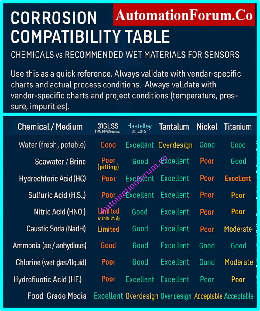
Corrosion Compatibility Table – Chemicals vs. Recommended Materials
This table provides a quick reference for Instrumentation EPC design engineers when selecting sensor wet part materials for different chemicals and environments. Always validate with vendor-specific compatibility charts and project conditions (temperature, pressure, impurities).
Chemical / Medium
316L Stainless Steel
Hastelloy C-276
Tantalum
Nickel
Titanium
Monel
Notes
Water (fresh, potable)
Good
Excellent
Overdesign
Good
Excellent
Good
316L is sufficient; others are overengineered.
Seawater / Brine
Poor (pitting)
Good
Excellent
Poor
Excellent
Good
Titanium preferred; Monel acceptable.
Hydrochloric Acid (HCl)
Poor
Excellent
Excellent
Poor
Poor
Limited
Tantalum is the safest; Hastelloy often used.
Sulfuric Acid (H2SO4)
Poor
Excellent
Excellent
Poor
Moderate
Poor
Tantalum best for strong concentrations.
Nitric Acid (HNO3)
Limited (dilute only)
Good
Excellent
Poor
Good
Poor
Stainless or Titanium ok in low conc.; Tantalum for strong acid.
Caustic Soda (NaOH)
Limited
Good
Good
Excellent
Good
Moderate
Nickel is the best choice; stainless not suitable in high conc.
Monel is one of the few materials resistant to HF.
Organic Solvents
Good
Excellent
Excellent
Good
Excellent
Good
Most materials acceptable; selection based on secondary impurities.
Food-Grade Media
Excellent
Overdesign
Overdesign
Acceptable
Acceptable
Acceptable
316L is the industry standard.
Emerging Trends in 2025 and Beyond
More people are using duplex and super duplex stainless steels for marine and offshore applications.
Utilization of modern composites and non-metallics in very corrosive environments.
In EPC projects, digital twins are used to model how long materials will last before they corrode.
Artificial intelligence-based compatibility calculators that use past data to guess which wet parts will work best together.
For Instrumentation EPC design engineers, choosing the right wet part materials is an important part of making sure that a plant works well. 316L stainless steel works for most ordinary uses, but for tougher jobs, you could need Hastelloy, Titanium, Monel, Nickel, or even Tantalum.
The most important thing to remember is to always weigh performance, safety, lifecycle cost, and availability. EPC engineers may make sure that:
FAQ on Right Wet Part Materials of Sensors in Process Industries
1. Which material is used in sensors?
Silicon (MEMS sensors), metals and ceramics (high-temp/corrosive), and polymers (flexible or biocompatible applications) are all common materials for sensors.
2. What is a wetted part material?
A wetted part material is any part of a sensor or transmitter that touches the process fluid directly. This affects how well it resists corrosion and how long the sensor lasts.
3. What materials are used in pressure sensors?
People often use silicon, stainless steel, ceramics, and sapphire, and they choose which one to use based on the temperature, pressure, and chemical exposure.
The wet leg is a reference leg that is filled with liquid to make sure that differential pressure measurements are correct and to keep things from getting clogged.
7. Which wet material is best for hydrochloric acid?
Because it is very resistant to corrosion, tantalum is the safest choice for powerful hydrochloric acid. Hastelloy C-276 can also be employed at concentrations that are not too strong.
8. When should Tantalum be used for sensors?
Use Tantalum only in very acidic situations where other materials, like stainless steel or Hastelloy, would not work. It works best with high quantities of hydrochloric or sulfuric acid.
9. What is the most cost-effective material for seawater?
Titanium is better for marine applications because it is more resistant to chloride and lasts a long time. It is a more reliable choice than 316L stainless steel or Monel.
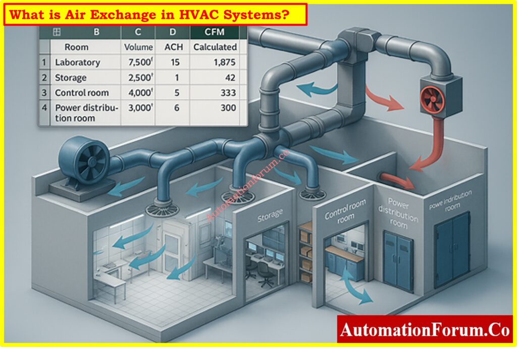
HVAC systems are the most important part of safe and efficient operations in process industries like oil and gas, petrochemicals, pharmaceuticals, and specialty chemicals. The air exchange rate, or air changes per hour (ACH), is one of the most important design factors in HVAC engineering.
Air exchange shows you how often the room or enclosure’s entire volume of air is replenished with new or conditioned air. Calculating air exchange rates correctly makes sure that safety regulations are met, stops dangerous gasses from building up, keeps equipment working well, and keeps the air within safe for workers.
Design engineers often use customized tools to make this calculation easier. This post talks about a thorough Air Exchange Calculation Excel Tool that is made just for HVAC use in process industries. The tool is meant to help engineers quickly figure out how much airflow in cubic feet per minute (CFM) is needed based on the size of the room and the ACH needs.
What is Air Exchange in HVAC Systems?
Air exchange is the process of replacing the air inside a building with fresh or conditioned air over a set amount of time. ACH, or Air Changes per Hour, is how it is measured.
High ACH = safer air quality (labs, cleanrooms).
Low ACH = acceptable for general spaces (warehouses, offices).
In process industries, bad air exchange design can lead to:
Buildup of hazardous gases.
When electrical equipment gets too hot
Bad working conditions for operators
Higher costs of doing business
Why Air Exchange is Important in Process Industry HVAC Design
Process organizations have settings with different needs:
Control rooms need to keep operators comfortable and make sure that important equipment is stable.
Laboratories need a lot of fresh air to mix and get rid of odors that could be hazardous.
Electrical rooms need enough air flow to keep switchgear, drives, and UPS systems from getting too hot.
To keep the quality of the products high, cleanrooms must keep stringent particle counts.
Warehouses and storage spaces need enough air flow to keep vapors from building up and to make sure that workers are safe.
If air exchange is not constructed well, the room could fill up with hazardous or combustible gasses or get too hot. If the system is over-designed, it will use a lot of energy and cost a lot to run. So, an optimal calculation is necessary.
Refer the below link for Quickly Estimate Fan Airflow Resistance Accurately with our HVAC Fan Static Pressure Calculator – Accurate Airflow Resistance Estimator for Fan Sizing
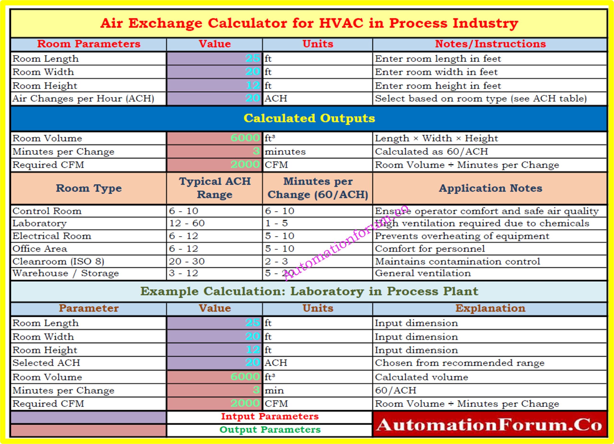
Air Change per Hour (ACH) indicates you how many times the air in a room or other enclosed space is totally replaced with fresh or conditioned air in an hour. It is a key factor in HVAC design since it has a direct impact on safety, comfort, and the quality of the air inside. A greater ACH means cleaner air since it gets rid of pollutants, gases, or extra heat more often. This is important in places like labs, cleanrooms, and hospitals. In places like offices, warehouses, or storage facilities where air quality isn’t as important, lower ACH levels are usually okay.
Download the Air Exchange Calculation Excel Tool for HVAC Systems(Free)
Our Air Exchange Calculation Excel Tool is ready to use and intended for process industry engineers to help you with your HVAC design process.
You can get it immediately by clicking the link below:
The performance of the HVAC system has a direct effect on the safety and air quality in process facilities. It is very important to get the air exchange rates right for:
Getting rid of dust, pollutants, and vapors.
Keeping the temperature of equipment (in electrical rooms and control rooms) constant.
Making sure that OSHA, ASHRAE, and municipal codes are followed.
Keeping labs and cleanrooms safe.
Balance Efficiency and Safety
In process industries, calculating air exchange is an important part of HVAC design. Engineers can make sure that systems are safe, work well, and follow the rules by figuring out the right airflow in CFM depending on the room size and ACH.
The Air Exchange Calculation Excel Tool is a useful tool for design engineers since it lets them do calculations quickly, accurately, and consistently. It connects theoretical design with real-world use by providing built-in reference tables, worked examples, and automatic formulae.
This tool is more than simply a calculator for process industry engineers who design HVAC systems. It is a decision-support system that makes sure that safety, reliability, and efficiency are maintained in a wide range of applications.
Common Questions About Air Exchange in HVAC Systems
One of the most important factors in process industries is level measurement. Accurate knowledge of liquid levels inside tanks, separators, and columns is essential for safe operation, process optimization, and product quality in a variety of industries, including oil and gas production, chemical refining, and power generation.
However, when two immiscible liquids (such as water and oil) are present in the same vessel, level measurement becomes especially difficult. Additionally, between the two layers, emulsions a mixture of the two liquids frequently form, making it even more difficult for traditional measurement technologies to produce accurate readings.
This is where the industry-changing Hybrid Level Measurement system, which combines Guided Wave Radar (GWR) and Capacitance Technology, comes in. This hybrid system guarantees stable level and interface detection even under the most taxing circumstances by combining the dielectric sensitivity of capacitance with the accuracy of radar.
The hybrid level measurement principle, diagram explanation with important symbols and zones, probe measuring ranges, handling emulsion layers, benefits and drawbacks, probe selection, installation and calibration procedures, industry applications, and troubleshooting advice are all covered in this article.
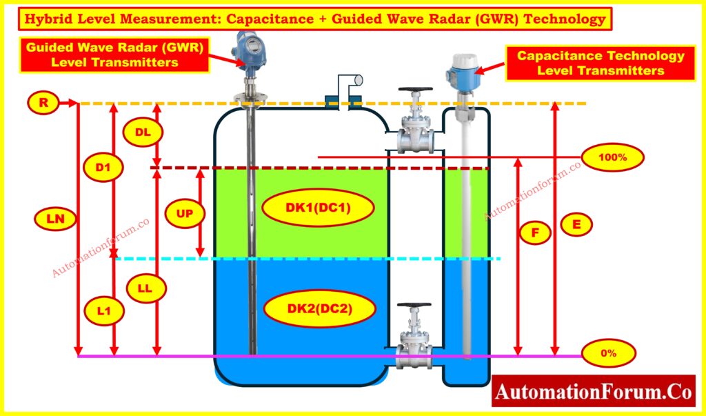
Explaining the Hybrid Level Measurement Diagram
In order to measure the overall liquid level and the interface level between two immiscible liquids (such as water and oil), the above image shows how Capacitance + Guided Wave Radar (GWR) technologies are combined inside a process vessel.
Let’s break it down step by step:
GWR Principle in Hybrid Systems
These devices are mounted at the top of the tank and use microwave pulses to send signals down a probe. By identifying signal reflections brought on by a change in the dielectric constant, they are able to determine the overall liquid level (upper layer, such as oil).
Refer the below link to Explore the complete guide to GWR troubleshooting and maintenance
By examining the liquids’ dielectric characteristics, these probes determine the levels of interfaces (such as the oil-water boundary). This is especially helpful for finding conductive materials beneath hydrocarbons, like water.
The hybrid system’s true strength lies in its ability to detect interfaces.
Clear Interface:
GWR gauges the general level, such as that of oil.
The interface (oil/water boundary) is measured by capacitance.
Emulsion Present:
Because radar signals are scattered or absorbed, traditional GWR frequently fails.
By examining the liquids’ dielectric values, capacitance makes up for it.
Result: Although precise emulsion thickness may not be measurable, the hybrid system still offers trustworthy oil + water level detection.
Outcome: Even in challenging emulsion conditions, hybrid systems produce reliable results in water treatment facilities, refinery desalters, and oil-water separators.
Dielectric Dependency: Variations in the dielectric constant determine measurement accuracy; abrupt changes can compromise dependability.
accumulation Sensitivity: Probe coating made of sticky or viscous materials may alter capacitance response and necessitate regular cleaning.
Foam & Vapor Interference: Signal clarity may be distorted by excessive foam, variations in vapor density, or turbulence.
High-Pressure Constraints: Capacitance probes may not be able to withstand high pressure ranges, even though GWR manages pressure well.
Temperature Influence: Significant temperature variations may cause capacitance readings to change, necessitating recalibration or compensation.
Maintenance Requirement: To prevent drift and guarantee that the capacitance and GWR channels remain aligned, combination probes require appropriate maintenance.
Dual Technology Assurance: By combining capacitance and radar, Dual Technology Assurance ensures dependable operation even in the event that one signal deteriorates..
Improved Accuracy: Improved performance in difficult situations such as emulsions, foams, and low dielectric media.
Interface & Level in One Device : This device measures the interface level and the overall tank level simultaneously.
Decreased Process Downtime: Redundancy reduces the likelihood of unplanned failures.
Wider Application Range: Water-based liquids, chemicals, slurries, and hydrocarbons can all be used with it.
Robust in Harsh Environments: Able to withstand high temperatures, high pressures, and corrosive service conditions.
Cost Optimization Over Time: Longer probe life, improved reliability, and fewer shutdowns offset higher initial costs.
Smart Diagnostics: Predictive maintenance alerts are integrated into modern devices to enhance asset management.
monitoring the level in storage tanks with different dielectric characteristics.
ideal for difficult process conditions, such as foams or emulsions.
utilized in power generation facilities, chemical plants, and refineries.
Best Practices for Long-Term Reliability
Inconsistent readings: Look for probe fouling.
Verify the dielectric constants if there is no interface detection.
Noisy signals: Avoid agitator zones and strengthen grounding.
Check the dielectric entries again for calibration drift.
Why Hybrid Capacitance + GWR is the Future
One of the most dependable methods for contemporary process industries is Hybrid Level Measurement using Capacitance + Guided Wave Radar (GWR). Even in cases where emulsions make measurement more difficult, it provides precise overall level and interface detection by fusing the accuracy of radar with the dielectric sensitivity of capacitance.
Excellent performance is ensured by careful probe selection, proper installation, and proper calibration, despite certain limitations with regard to dielectric ranges and probe fouling.
Hybrid Capacitance/GWR technology is quickly taking over as the industry standard for oil-water interface measurement, desalters, separators, and chemical process units due to industry demands for increased accuracy, safety, and efficiency.
Refer the Following link for calibration steps for precise capacitance level measurement
FAQs on Level Measurement and Hybrid Capacitance + Guided Wave Radar (GWR)
What are the different types of level measurements?
Depending on the application, level measurements can be made directly (using sight glasses or floats) or indirectly (using hydrostatic pressure, capacitance, ultrasonic, radar, GWR, nuclear, and hybrid systems)..
What is the hydraulic method of level measurement?
The hydraulic method uses a pressure balance system to determine the liquid level. Level is indicated by the differential pressure, which is balanced against the liquid column by a connected pressure line.
What is the Hydra step method of level measurement?
Several probes are used in the capacitance-based Hydra step method to measure the water-steam ratio in boilers. For precise drum level monitoring, it offers distinct steps.
What is the hydrostatic method of level measurement?
The idea that liquid pressure at a depth is proportional to liquid height and density is the basis for the hydrostatic method. For this technique, differential pressure transmitters are frequently employed.
What is hybrid level measurement in process industries?
Even in emulsions, hybrid level measurement reliably measures both the overall liquid level and the interface level by combining Guided Wave Radar (GWR) and Capacitance technologies.
Why use hybrid Capacitance + GWR instead of standalone transmitters?
Redundancy is provided by hybrid transmitters. Capacitance provides precise interface detection, while GWR guarantees accurate total level. For emulsions and oil-water separators, this combination is perfect.
Can hybrid GWR-capacitance transmitters work in foamy or turbulent tanks?
Yes. Stable operation in turbulent or foamy process conditions is made possible by capacitance correction, coaxial probes, and stilling wells.
Where are hybrid level measurement systems used?
For precise interface detection, they are extensively utilized in petrochemical facilities, power generation, desalters, oil and gas separators, and chemical processing units.
How do emulsions affect level measurement and how does hybrid solve this?
Radar signals are scattered by emulsions, rendering standalone GWR unreliable. Reliable interface measurement is ensured by the capacitance channel compensating by detecting dielectric differences.
Resistance Temperature Detectors (RTDs) are one of the most reliable and commonly used sensors for measuring temperature in HVAC,process control, and industrial automation systems. In many cases where moderate temperature ranges and precise measurements are needed, they are better than thermocouples because they are more accurate, repeatable, and stable over time.
The IEC 60751 standard sets accuracy classes for RTDs, which tell you how much the temperature readings can change in different working ranges. Class C RTDs are the lowest standard accuracy class, which means they can have the biggest tolerance band. Class C RTDs are not as accurate as Class A and B, but they are good for situations where cost is more important than precision.
This article talks about Class C RTD tolerance, gives the formula and reference table, compares the accuracy classes of Class A, B, and C, and gives you a free RTD Class C Tolerance Calculator to make calculations easier.
What is RTD Accuracy Class According to IEC 60751?
There are accuracy classifications for platinum RTDs (such Pt100, Pt500, and Pt1000) in IEC 60751. Each class tells you how much the measured temperature can be different from the real temperature.
Accuracy depends on:
The class formula (the equation for tolerance).
The temperature at which the measurement is taken.
The quality of the sensor’s construction and calibration.
IEC 60751 Accuracy Class Formulas
The IEC 60751 and expanded DIN standards set the following tolerance formulas:
Class A: Δt=±(0.15+0.002⋅∣T∣)
Class B: Δt=±(0.30+0.005⋅∣T∣)
Class C: Δt=±(0.60+0.01⋅∣T∣)
1/3 DIN: Δt=±(0.10+0.0017⋅∣T∣)
1/10 DIN: Δt=±(0.03+0.0005⋅∣T∣)
Here,
Δt = tolerance in °C
∣T∣ = absolute temperature in °C
Note: |T| is the temperature in °C, which makes sure the formula works for both positive and negative values.
What is the Tolerance of a Class C RTD?
The tolerance of a Class C RTD tells you how accurate it is at a certain temperature. Class C RTDs have the widest tolerance band of all the classes. This means they are good for situations where accuracy isn’t the most critical thing, but affordability and durability are.
The table below shows the tolerance levels for different accuracy classes at important temperatures:
Temperature (°C)
Class A (°C)
Class B (°C)
Class C (°C)
1/3 DIN (°C)
1/10 DIN (°C)
-200
±0.55
±1.30
±2.60
±0.44
±0.13
-100
±0.35
±0.80
±1.60
±0.27
±0.08
0
±0.15
±0.30
±0.60
±0.10
±0.03
100
±0.35
±0.80
±1.60
±0.27
±0.08
200
±0.55
±1.30
±2.60
±0.44
±0.13
300
±0.75
±1.80
±3.60
±0.61
±0.18
400
±0.95
±2.30
±4.60
±0.78
±0.23
500
±1.15
±2.80
±5.60
±0.95
±0.28
600
±1.35
±3.30
±6.60
±1.12
±0.33
650
±1.45
±3.55
±7.10
±1.20
±0.36
This table now has Class C values next to Class A, B, and extended DIN classes, which makes it complete.
IEC 60751 Accuracy Classes – Tolerance vs Temperature Curve
The graph below shows the acceptable tolerance (in °C) for different RTD accuracy classes as set by IEC 60751 and expanded DIN standards. For regularly used classes like Class A, Class B, Class C, 1/3 DIN, and 1/10 DIN, each graph shows how the maximum permitted inaccuracy goes up as the temperature goes up.
Class A and B are the standard IEC 60751 categories. They are commonly used in industrial RTDs.
Class C is less accurate and should only be used for non-critical tasks.
1/3 DIN and 1/10 DIN are stricter tolerance levels that are typically utilized in labs or for precision control systems.
The above image makes it easy to see how the accuracy limits of different RTD classes compare across the whole operating range (–200 °C to +650 °C). This curve helps engineers choose the right RTD class for a job by weighing factors including accuracy, cost, and environmental conditions.
Class C RTDs are utilized when saving money and having a reasonable amount of tolerance are more important than getting exact measurements. Some such uses are:
HVAC stands for heating, ventilation, and air conditioning.
Monitoring the environment and automating buildings
Industries that work with general processes and can handle wide tolerances
Checking on food storage and cold rooms (non-critical ranges)
Systems for managing energy
Watching over the refrigerator and freezer
Alarms and indicators for temperatures that aren’t critical
Training and educational labs where high accuracy isn’t needed
Benefits of using the RTD Class C Tolerance Calculator
Engineers, technicians, and project managers can use this calculator for a number of reasons:
Makes ensuring that the IEC 60751 Class C tolerance requirements are followed.
Calculates tolerance at any temperature automatically, saving you time.
Helps choose sensors for big, expensive projects.
Gives handy reference values for tolerance in °C and ohms.
Helps with troubleshooting in the field when RTD readings go wrong.
Lowers the danger of over-specification, which lowers the cost of buying things.
Engineers working on cost-sensitive projects where accuracy isn’t the most important thing need the RTD Class C Tolerance Calculator. It quickly finds the allowable deviation values in °C and ohms across the RTD’s operating range by using the IEC 60751 Class C formula.
Class C RTDs are the least accurate of all IEC-standard RTDs, but they are nonetheless reliable, strong, and very helpful in HVAC, building automation, and general monitoring systems. Knowing their tolerance helps you avoid over-specifying, saves money, and makes sure you get the right sensor.
When accuracy is very important, you should choose Class A, Class B, or specific tolerances like 1/3 DIN or 1/10 DIN. Class C RTDs, on the other hand, are the best choice for non-critical monitoring since they are the ideal mix of cost and performance.
IEC 60751 accuracy classes, such as Class A, Class B, and Class C, as well as stricter DIN extensions (1/3 DIN, 1/10 DIN), are used to group RTDs. These set the limitations for accuracy and tolerance.
2. What is the tolerance class of RTD?
Tolerance classes tell you how much inaccuracy is allowed:
Class A: ±(0.15 + 0.002|T|) °C
Class B: ±(0.30 + 0.005|T|) °C
Class C: ±(0.60 + 0.01|T|) °C DIN versions (1/3, 1/10) give even tighter tolerances.
3. What is the common resistance of an RTD at 0 °C?
The most popular RTD is the Pt100, which has a resistance of 100 Ω at 0 °C. There are also Pt500 (500 Ω) and Pt1000 (1000 Ω) variants.
4. What is the resistance of Pt100 at 0 °C?
At 0 °C, a Pt100 has a resistance of exactly 100.00 Ω, and it goes up by around 0.385 Ω/°C.
5. What is the tolerance class of Pt100?
Depending on how accurate they need to be, Pt100 sensors are made to IEC 60751 classes: Class A, B, C, or extended DIN classes.
6. What is the range of Class A RTD?
The range of Class A RTD is: –100 °C to +450 °C (more accurate, but less range than Class B).
7. What is the range of Class B RTD?
Class B RTD range: –196 °C to +600 °C (standard precision, most commonly used in industry).
8. How accurate is Class A vs Class B RTD?
At 100 °C:
Class A: ±0.35 °C
Class B: ±0.80 °C
Class A is nearly twice as precise as Class B.
9. What is the difference between Class A and Class B Pt100?
Accuracy: Class A is more accurate than Class B.
Class B’s range is bigger than Class A’s.
Cost: Class A costs extra.
Applications: Class A is for calibration and pharmaceuticals, while Class B is for general industrial application.
In July 2024, a serious security flaw was found in Rockwell Automation ControlLogix 1756 devices. These devices are used in many industries, including oil and gas, chemical processing, water treatment, power generation, and advanced manufacturing. This vulnerability, known as CVE-2024-6242, has a CVSS v3.1 score of 8.4, which means it is a serious problem.
The issue makes the Trusted Slot function, which is a key security element in Rockwell chassis environments, less effective. Attackers can transmit illegal commands to the CPU through a trusted module by taking advantage of a flaw in Common Industrial Protocol (CIP) routing. This allows them get around slot-level constraints.
Claroty’s Team82 found this vulnerability, and CISA later validated it. It has big effects on the cybersecurity of industrial control systems (ICS). The following article discusses the technical details, how the Rockwell ControlLogix CVE-2024-6242 vulnerability can be used, how to fix it, and what we learned from it.
Background on Rockwell ControlLogix 1756 Devices
The ControlLogix 1756 chassis is the main part of Rockwell’s modular PLC platform. The backplane connects all the modules in each chassis, which can be of different sorts.
These are the brains of the system; they run process control, structured text, and ladder logic commands. The automation system can’t do its main jobs without them.
Importance of I/O Modules in Process Control
These connect directly to sensors and actuators in the field. Digital and analog I/O cards deal with signals from real-world processes, which makes them very important for connecting the control system to plant equipment.
Some examples are 1756-EN2T, EN2TR, EN3TR, EN4TR, and EN2TP. These cards connect the chassis to Ethernet/IP networks, which lets you monitor, set up, and talk to SCADA or DCS systems from a distance.
Refer the below link to Differentiate PLC racks and chassis easily:
Rockwell included the Trusted Slot functionality to lower the risk of illegal communications inside the chassis. The reasoning is simple:
How Trusted Slot Restricts Unauthorized Commands
Administrators can mark certain chassis slots as “trusted.” These are usually the slots that carry network interface modules that engineers use to upload or download logic.
When targeting the CPU, every command that comes from an untrusted slot is turned down. This stops bad or rogue cards from giving sensitive commands like forcing I/O, uploading new logic, or overwriting projects.
This technique, on the other hand, enforces a security boundary at the chassis level. This gives operators assurance that only verified modules can send high-privilege commands to the CPU.
This process should, in theory, create significant separation. But the Rockwell ControlLogix CVE-2024-6242 vulnerability shows a big hole in how this validation is done.
Claroty’s Team82 found out that the Trusted Slot protection doesn’t adequately check the pathways of CIP (Common Industrial Protocol) messages.
CIP Routing Weakness in Rockwell PLCs
CIP allows requests move between different modules and slots by using path-based communication.
When everything is working normally, an engineer’s workstation sends a packet to the CPU through a network card. The trail tells you what each “hop” across the chassis is.
But this flexibility also makes it possible to hide the real source of a request by routing it in a roundabout way.
CPU Validation Limitation – Why It Fails
When the CPU processes a CIP packet, it merely checks the last hop in the chain.
The CPU thinks the request is safe if that last hop is in a trusted slot.
The CPU doesn’t check to see if the request came from an untrusted slot before going via the trusted one.
Technical Deep Dive: CIP Paths and Backplane Addressing
The Common Industrial Protocol (CIP) makes it possible to route Rockwell systems in great detail.
Each chassis slot has its own number that is different from all the others.
Forward Open Requests explain communication by showing how messages move across the network and chassis.
For example:
A legitimate path might be Engineering Workstation → EN2T (Trusted Slot) → CPU.
An exploit path could be Attacker → Untrusted Slot → EN2T (Trusted Slot) → CPU.
The CPU carries out the malicious request even though it came from an untrusted source since it only checks that the last step goes through the EN2T (trusted slot).
This design flaw makes the Trusted Slot functionality useless against smart attackers who know how CIP routing works.
A real-world attack that takes use of the Rockwell ControlLogix CVE-2024-6242 vulnerability could go like this:
Step 1: Getting into the OT Network for the First Time
The attacker gets access via breaking into a remote engineering workstation or by using a poorly segmented OT/IT network.
Once they’re inside, they can use regular CIP discovery techniques to look for ControlLogix chassis modules.
Step 2: Crafting the Malicious CIP Packet
The attacker makes a CIP packet that first goes via a trusted slot (like EN2T) before getting to the CPU. They do this by knowing how the slots are set up.
This makes the request look real.
Step 3: CPU Accepts Command from Trusted Slot
The CPU checks and carries out the request because the last hop is from a trusted slot.
The system doesn’t know where the untrusted source came from.
Step 4: Execution of Malicious Intent (Logic Injection, Shutdown, Damage)
The attacker can download any ladder logic they want to mess with process flows.
They might change configuration files to hide that they are there.
In the worst instances, they could stop all operations, which would make things less safe and less available.
This example shows how a mistake in a protocol might make a hardware-enforced security feature useless, which could put vital infrastructure at risk.
Affected Products and Fixes (Firmware / Replacement)
Rockwell has acknowledged that a number of product lines are compromised. Some of them need firmware updates, while others need to have their hardware completely replaced.
Product
First Affected Firmware
Fixed Firmware
Notes
ControlLogix 5580 (1756-L8z)
V28
V32.016, V33.015, V34.014, V35.011+
Update required
GuardLogix 5580 (1756-L8zS)
V31
V32.016, V33.015, V34.014, V35.011+
Update required
1756-EN4TR
V2
V5.001+
Update required
1756-EN2T (Series A/B/C)
V5.007 / V5.027
No fix – must upgrade to Series D
Hardware replacement
1756-EN2F (Series A/B)
Same as above
No fix – upgrade to Series C
Hardware replacement
1756-EN2TR (Series A/B)
Same as above
No fix – upgrade to Series C
Hardware replacement
1756-EN3TR (Series A)
Same as above
No fix – upgrade to Series B
Hardware replacement
1756-EN2T (Series D)
V10.006
V12.001+
Update required
1756-EN2F (Series C)
V10.009
V12.001+
Update required
1756-EN2TR (Series C)
V10.007
V12.001+
Update required
1756-EN3TR (Series B)
V10.007
V12.001+
Update required
1756-EN2TP (Series A)
V10.020
V12.001+
Update required
This table highlights a major challenge: Older hardware series (A/B) can’t be patched and have to be replaced, which costs a lot of money and time for operators.
The Rockwell CVE-2024-6242 problem teaches us a few essential things:
Hardware Trust Alone Is Not Enough: If the communication protocol doesn’t have strong validation, even chassis-level slot enforcement can be gotten around.
Collaboration between vendors and researchers is very important: The relationship between Claroty, Rockwell, and CISA made it possible to quickly release detection signatures, vendor alerts, and other information.
We need secure-by-design protocols: To eliminate path spoofing, future versions of CIP and other ICS protocols should include cryptographic source validation.
Defense-in-Depth is Not Up for Discussion: Operators must expect that any one control could fail. The only long-term solution is to use numerous detection and preventive methods.
It’s important to plan for the whole life cycle:Security should be a top priority in managing the lifecycle of assets, not something that comes up later when problems arise.
This vulnerability is extremely problematic in today’s operational contexts, when IT and OT networks are coming together more and more.
Remote Engineering Access: Cloud-based SCADA or vendor maintenance sessions make more entry points possible.
Integrators from Other Companies: Contractors often connect laptops or temporary modules, which makes it easy for an untrusted slot to be added without anybody knowing.
IoT and Edge Devices: Devices on the Internet of Things (IoT) and the Edge As plants start using IIoT sensors and edge gateways, more devices are on the same network as core PLCs. This makes it more likely that attackers will go sideways.
Securing Rockwell ControlLogix PLCs Against CVE-2024-6242
The Rockwell ControlLogix CVE-2024-6242 vulnerability shows that protocol design issues can make even trusted hardware-based defenses less effective. Attackers can use CIP routing to get beyond Trusted Slot enforcement and directly attack the CPU, putting important industrial systems at risk of sabotage, disruption, or manipulation.
Use a defense-in-depth strategy that includes firmware updates, monitoring, and splitting up the architecture.
This story shows that industrial automation needs more than one layer of protection to stay safe. No one feature, not even a hardware-level protection like Trusted Slot, can guarantee safety. To keep modern industrial networks safe, you need to always be on the lookout, manage their lifecycles, and find threats before they happen.
CVE-2024-6242 is the main issue at the heart of the dispute. It is a serious weakness in Rockwell ControlLogix 1756 PLCs. Attackers can get around the Trusted Slot feature and send commands that aren’t allowed, which puts electricity, oil and gas, and manufacturing industries at danger.
Who are the biggest customers of Rockwell Automation?
Rockwell’s key customers are in the oil and gas, energy, water treatment, automotive, pharmaceuticals, and advanced manufacturing industries. A lot of Fortune 500 firms use its ControlLogix PLCs and FactoryTalk software.
What is the Trusted Slot feature in Rockwell?
It is a security setting at the chassis level that marks certain slots as trusted. Only modules that fit in these slots, which are usually network cards, can send critical orders to the CPU.
Is Rockwell Automation product based or service based?
Rockwell is mostly a product-based company that sells PLCs, drives, and automation software. It is a hybrid supplier because it also offers services including system integration, lifecycle support, and cybersecurity.
Refer the below link for How to Safeguard PLCs Against Cyber Attacks in Industrial Networks ?
What is the main security flaw in the access control system provided in the code?
The problem is that the CPU only checks the last step in CIP routing. Attackers can get around constraints and get privileged access by sending requests through a trusted slot.
What is a weakness or flaw in a system’s security that can be exploited?
A problem like this is called a vulnerability. Attackers can take advantage of things like weak protocols, old firmware, or bad network segmentation.
What is the Trusted Slot feature?
The Trusted Slot feature is a Rockwell security feature that makes sure that only modules in approved slots can talk to the CPU at a high privilege level.
Refer the below link for Essential documentation practices for PLC systems:
Importance of Accurate Boiler Drum Level Measurement
One of the most important things that power plants and process industries need to do is measure the water level in a boiler steam drum accurately. A boiler drum is a pressurized container that holds both water and steam. It is very important to keep the right water level:
If the water level is too low, the boiler tubes could get too hot and break.
High water level might result in water carryover with steam, damaging turbines or downstream process equipment.
Operators used to use a sight glass (gauge glass) to see the level directly. With automation, though, a Differential Pressure (DP) type level transmitter is currently the most common way to measure levels continuously, from a distance, and accurately.
The installation of a DP transmitter in a pressured steam drum is a very important job that requires a good understanding of impulse lines, isolating valves, condensate (gas trap) pots, equalizing valves, and calibration procedures.
This article explains the working principle, commissioning steps, and valve operation in detail with reference to the provided below diagram.
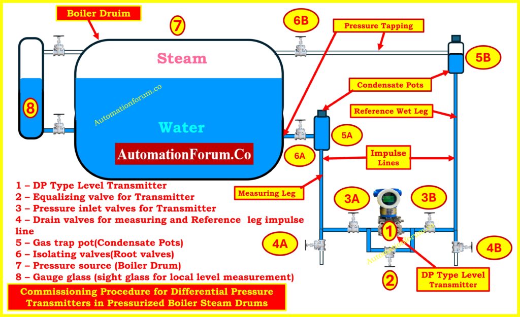
Components in a DP Transmitter Installation (Diagram Explained)
DP Type Level Transmitter (1) – The DP Type Level Transmitter (1) is the principal tool that measures the difference in pressure between the water leg (the measuring leg) and the steam leg (the reference leg).
Equalizing Valve (2) – During zero checks, it connects the high-pressure and low-pressure sides of the transmitter..
Pressure Inlet Valves (3A & 3B) – Pressure Inlet Valves (3A and 3B) connect the transmitter to the impulse lines in the process.
Drain Valves (4A & 4B) – Drain Valves (4A and 4B) are used to get rid of air, condensate, or debris from impulse lines.
Gas Trap Pots / Condensate Pots (5A & 5B) – Gas Trap Pots and Condensate Pots (5A and 5B) collect condensate and keep a water seal so that live steam can’t get into the transmitter.
Isolating Valves (6A & 6B) – Isolating Valves (6A and 6B) are the main isolation (root) valves that link the boiler drum to the impulse lines.
Boiler Drum (7) – Boiler Drum (7) is the container that holds both steam and water under pressure.
Gauge Glass (8) – Gauge Glass (8) lets you see the water level directly so you can check it.
The diagram also highlights:
Measuring Leg – This is the part of the drum that connects to the water space (lower tapping).
Reference Wet Leg – Connected to the steam area (upper tapping) and kept full of condensate water by trap pots.
Impulse Lines – Impulse Lines are the pipes that connect the boiler tappings to the transmitter.
No matter what the steam pressure or temperature is, this setup makes sure that the DP transmitter measures the real amount of water inside the drum.
Principle of Differential Pressure Measurement in Steam Drums
The DP transmitter works by measuring the hydrostatic head:
The water leg at the bottom of the steam drum is connected to the high-pressure side (HP).
The wet reference leg connects the low-pressure side (LP) to the steam space.
The water leg at the bottom of the steam drum is connected to the high-pressure side (HP).
The wet reference leg connects the low-pressure side (LP) to the steam space.
Mathematically:
ΔP=(h×ρwater×g)−(href×ρref×g)
Where:
h = height of water column in the measuring leg
href = height of reference leg (kept filled with condensate)
ρ = density of fluid
g = acceleration due to gravity
Because water is significantly denser than steam, the difference in pressure between these two legs is directly related to the water level inside the drum.
Refer the below link for the Comprehensive collection of level measurement calculators for instrumentation
In pressurized steam drums, the reference leg must be a wet leg (filled with condensate) to guarantee a stable hydrostatic head reference. If the reference leg contains steam pockets or air, the DP transmitter will see fluctuating or erroneous pressure, causing wrong level readings. So, before completing any zeroing or signal checks, you need to make sure that the condensate pots and impulse lines are properly filled and vented.
Before starting commissioning, perform the following:
Calibration and Configuration
Set transmitter LRV (Lower Range Value) and URV (Upper Range Value) based on drum level range.
Configure display units (mmH₂O, bar, or %).
Adjust damping factor to filter out noise.
Set error/fail-safe mode output.
Use a HART communicator or field device management software for parameter configuration.
Mechanical Verification
Ensure correct mounting of the transmitter (below drum level).
Check impulse lines for leaks, the right slopes, and no sharp bends.
Make sure that the root valves, equalizing valve, and drain valves are all in the right places.
Safety Precautions
The boiler needs to be filled with water and pressured.
Operators must wear PPE, like gloves that don’t get hot from steam and a face shield.
To stop water hammer, valves must be opened and closed carefully.
Step-by-Step Commissioning Procedure for Boiler Drum DP Transmitters
The commissioning sequence is critical for protecting the DP transmitter and ensuring accurate measurement.
Important: operate all valves slowly and in small increments. Watch the gauge glass and gauge pot vents for water/steam appearance. Do not rush.
Step 1 – Initial Condition and Checks
Close all the valves first: 6A, 6B, 3A, 3B, 4A, 4B, and equalizer 2. Check that the transmitter is on and able to talk to the HART communicator. Check the condensate pots (5A/5B) for plugs that aren’t tight. Confirm gauge glass shows a reasonable water level between the taps. This “all closed” starting point ensures no trapped steam or pressure surge can reach the transmitter unexpectedly.
Step 2 – Filling the Measuring Leg
Carefully crack open 6A (lower/water-side isolating valve). The condensate pot 5A will begin to fill with water from the drum. Opening slowly reduces the chance of water hammer and gives time for the pot to collect condensate and flush any air into the vent path. Do not open any transmitter ports yet – this isolates the transmitter while the measuring leg fills.
Step 3 – Purging the Measuring Impulse Line
Open drain valve 4A slightly to purge the impulse line between the condensate pot and transmitter. Expect spurts of air or mixed fluid first; continue until a steady stream of water (no air) flows. After purging is done, close 4A. This step makes sure that there are no gas pockets in the measuring impulse line or the way to the transmitter.
Step 4 – Venting the Measuring Condensate Pot
To let trapped gas out, momentarily open the vent plug on condensate pot 5A. This will also let you know that the pot is full of water. When you get solid water flow or the pot is visibly full, close the vent. At this point the measuring leg (from drum to transmitter) should be hydraulically wet and stable.
Step 5 – Filling the Reference (Wet) Leg
Now fill the reference (wet) leg. Slowly open 6B (upper/steam side root valve) a small amount. Because this side connects to steam, it must be handled even more carefully. Allow condensate to form and collect in condensate pot 5B. Do not rush – if steam blows through, close the valve and allow condensate to accumulate in the pot before repeating a small crack. The objective is to get the condensing steam to fill the pot with water so the reference leg becomes a wet leg.
Step 6 – Purging the Reference Impulse Line
Once 5B shows condensate, open drain valve 4B slightly to purge the reference impulse line, removing air and ensuring water flows in the line to the transmitter. Continue until you see steady condensate/water. Then close 4B.
Step 7 – Venting the Reference Condensate Pot
Open the vent plug on 5B briefly and allow trapped gases to escape. Close the vent after water consistently exits. At this stage both condensate pots and both impulse lines should be filled with water (wet). If not, repeat purging/venting in small increments until both legs are confirmed wet.
Step 8 – Opening Transmitter Inlet Valves with Equalizer
Before opening the transmitter inlet valves 3A and 3B, open the equalising valve (2) about one-quarter turn so the transmitter HP and LP ports will be equalized when 3A/3B are opened. Now open 3A and 3B slowly the transmitter will be tied into the wet impulse lines while equalizer 2 keeps both ports at the same pressure so there is no differential shock to the sensing element.
Step 9 – Venting the Transmitter
Slightly open the small vent screws on the transmitter body ports to allow any last air bubbles to escape; when water flows out solidly, close the vent screws. With equalizer open and both inlet valves open, the DP element should read zero differential (DP = 0). At this stage you are checking hydraulic connectivity (both legs full of liquid) not yet verifying the 4-20 mA LRV.
Step 10 – DP Zero Verification
With the equalizing valve (2) open and both inlet valves 3A/3B open and vents closed, the transmitter’s DP sensing element sees identical pressure on both sides DP = 0 Pa. Use the HART communicator and/or the transmitter display to confirm the DP value is zero (or within tolerance). If the transmitter displays a non-zero DP, there may still be trapped gas or a leak. If DP is zero but the transmitter output current does not read the expected 4 mA, do not immediately assume a fault. See Step 11 (the correct 4 mA verification sequence).
Important correction: With equalizer open you will reliably check that the DP sensing element is at zero pressure difference. However, you should expect to perform the definitive 4 mA/zero output verification only after both condensate pots and legs are fully filled and the transmitter is isolated per Step 11. The DP element will read “zero” first; the transmitter’s 4 mA output requires correct LRV configuration and a stable trapped hydraulic head to be confirmed.
To check that the transmitter is scaled correctly and will produce 4 mA at LRV, follow this safe procedure:
Close the equalizing valve (2). This returns the transmitter to differential sensing mode.
Close the isolating/root valves 6A and 6B at the drum tappings (one at a time, slowly) to isolate the process from the transmitter while leaving the condensate pots and impulse lines full. By closing both root valves you trap the hydraulic (wet) heads and prevent live steam/transients from the boiler affecting the transmitter during the check.
Now observe the transmitter output current. If the transmitter LRV is configured to correspond to the trapped head condition (i.e., the level associated with 0 DP differential as per your LRV definition), the output should read 4 mA. If it does not, perform an electronic zero (LRV) adjustment using the HART communicator so that the transmitter’s output at this trapped condition becomes 4 mA.
This isolated, wet-leg state is the correct condition to confirm the 4 mA LRV point because the hydraulic conditions are stable and not being influenced by live steam pressure or venting operations.
After checking the 4 mA and making any necessary zero adjustments, progressively open 6A and 6B to get everything back to normal. Monitor the transmitter output as the process pressure equilibrates; the transmitter will now read the actual differential corresponding to the real drum level. Finally, open or close 3A/3B as required for your operating logic and remove any temporary venting. Verify transmitter reading against the gauge glass.
Step 13 – Span (URV) Check and Final Calibration
If possible, use a calibrated pressure source or known level condition to verify the transmitter’s span (URV). Many teams verify by changing the drum level to a known point (or applying pressure) and confirming the transmitter reaches 20 mA at URV. Adjust span via HART if required. Re-check zero after span adjustment.
Step 14 – Recording Settings and Handover
Log the HART configuration parameters (LRV, URV, damping, units), any zero offsets that were used, and any leaks or purges that were out of the ordinary. Put a commissioning tag on the transmitter that has the date of commissioning and the name of the operator. Check with the control room or LSS to make sure the signal is coming through and the alarm setpoints are right.
DP-zero check (hydraulic): With the equalizer open and both inlet valves connected, you confirm that the DP element senses zero differential. This verifies impulse line connectivity and absence of gross air pockets or leaks. This is a hydraulic/mechanical check and should always be done first.
4 mA (LRV) check (electronic + hydraulic): A transmitter’s output at LRV equals 4 mA only if the transmitter LRV/zero setting corresponds to the trapped hydraulic condition and the sensing element and electronics are properly adjusted. For a reliable 4 mA verification you must (a) have both legs fully filled (wet), (b) close the equalizer, (c) close the drum root valves to trap the hydraulic head, then observe the output and perform the zero-trim via HART if needed. Doing the 4 mA check while equalizer is open is not a robust test.
Troubleshooting common observations during the steps
Air/gurgling during vents: Keep purging until consistent water only. Repeat venting of condensate pots if needed.
Transmitter shows non-zero DP with equalizer open: Likely a blocked port, leak, or trapped gas. Confirm tightness of 3A/3B/vent screws and repeat purge.
Output stuck above 4 mA after zeroing: Re-check that LRV is correctly defined, that there is no small trapped overpressure on one leg and that both legs are indeed wet.
Steam blows through condensate pot (5B) while filling): Close 6B and allow pot to cool/collect condensate slowly, then retry with smaller openings.
Provides inputs for boiler trips (low-low and high-high levels).
Can compensate for density variations at high temperature/pressure.
checking DP = 0 and checking transmitter output – 4 mA are related but distinct operations. The DP-zero (equalizer open) confirms hydraulic connectivity; the 4 mA LRV verification must be performed with both legs wet and isolated (equalizer closed and root valves closed) so the transmitter sees the stable trapped head corresponding to LRV. The expanded commissioning steps above include the explicit, safe sequence to fill the reference (wet) leg and to perform the correct zero and 4 mA checks.
In a pressurized boiler steam drum, commissioning a DP type level transmitter is a methodical process that makes sure level measurement is safe, reliable, and precise. The steps are as follows:
Making sure that all of the valves are closed at first.
Opening isolating valves one at a time, letting air pockets drain, then venting them.
Equalizing both sides for zero check.
Slowly introducing steam pressure to the reference leg.
The attached diagram clearly shows how isolation valves, pressure inlet valves, condensate pots, impulse lines, and gauge glass are integrated into the commissioning process.
A correctly set up DP transmitter makes sure that the boiler drum stays within safe limits, which saves expensive breakdowns and makes sure that steam is made efficiently.
Test Your Knowledge with 25 advanced MCQs on boiler control and interlock logic
Refer the below link test your knowledge on 25 advanced MCQs on boiler control and interlock logic for Instrumentation and Control Engineers
Cybersecurity in PLC systems is now one of the most important problems in the process industries. When plants go digital and connect to the internet from afar, threats like malware, unauthorized access, and network vulnerabilities can put safety, reliability, and production continuity at risk. This difficult quiz is for experienced engineers, control system experts, and cybersecurity professionals who work with PLC and SCADA/DCS systems. You will have to answer 25 hard multiple-choice questions about real-world vulnerabilities, standards (IEC 62443, NIST), defense-in-depth techniques, and how to fix problems. There are extensive answers and explanations for each question to help you learn. Test your knowledge and improve your skills against threats that are always changing in the business world.
Refer the below link for How to Safeguard PLCs Against Cyber Attacks in Industrial Networks ?
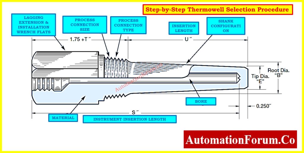
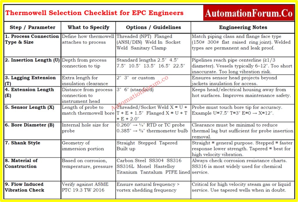
The American Society for Testing and Materials (ASTM) says that a thermowell is “a closed end re-entrant tube designed for insertion of a temperature sensing element and provided with means for a pressure-tight attachment to a vessel.” Thermowells are basically protective cases that hold temperature sensors like thermocouples,RTDs, or bimetallic thermometers. They are permanently installed in pipelines, tanks, or vessels so that sensors can be replaced, calibrated, or serviced without stopping the process or placing operators in hazards.
Choosing the right thermowell is an important design job for EPC engineers, instrumentation experts, and maintenance teams. If you choose the wrong thermowell, you could get wrong data, a sensor that doesn’t work, or even a mechanical breakdown that is really bad when there is pressure and vibration. This article gives you a step-by-step way to choose, using ASTM terminology, ASME PTC 19.3 criteria, and the best practices in the field.
Why Thermowells Are Essential
Thermowells do three jobs when it comes to measuring temperature in an industrial environment:
Protection: They protect fragile sensors against corrosion, erosion, pressure, and fast-moving fluids.
Isolation: They create a physical barrier that lets sensors be removed or calibrated without stopping the process.
Containment: When designed correctly, thermowells assist keep the process safe and stop dangerous or high-pressure fluids from leaking.
Without thermowells, temperature sensors would be directly exposed to process conditions, which would cause them to wear out quickly, pose safety issues, and need to be repaired often.
Basic Components of a Thermowell
Every thermowell has important dimensions and features that affect how well it works (see Figure – Thermowell Parts).
Bore Diameter (B): The inside diameter that was bored to fit the sensor probe. For ¼″ RTDs, the most common size is 0.260″, while for ⅜″ thermometer bulbs, it is 0.385″.
Bore Depth (S): The total depth that the probe can go into.
Insertion Length (U): This is also known as immersion length. It is the distance from the process connection to the end of the thermowell.
Lagging Extension (T): Extra length above the process connection to make room for insulation or jackets.
Extension Length (E): A longer length that moves the connecting head away from the heated surface.
Shank Construction: The shape of the stem that is submerged—straight, stepped, or tapered.
Base Diameter (Q): The thickest point on the outside of the shank.
Tip Diameter (V): The diameter of the thermowell tip’s outside edge.
Tip Thickness (E): The thickness of the closed end that keeps the process and the sensor tip apart.
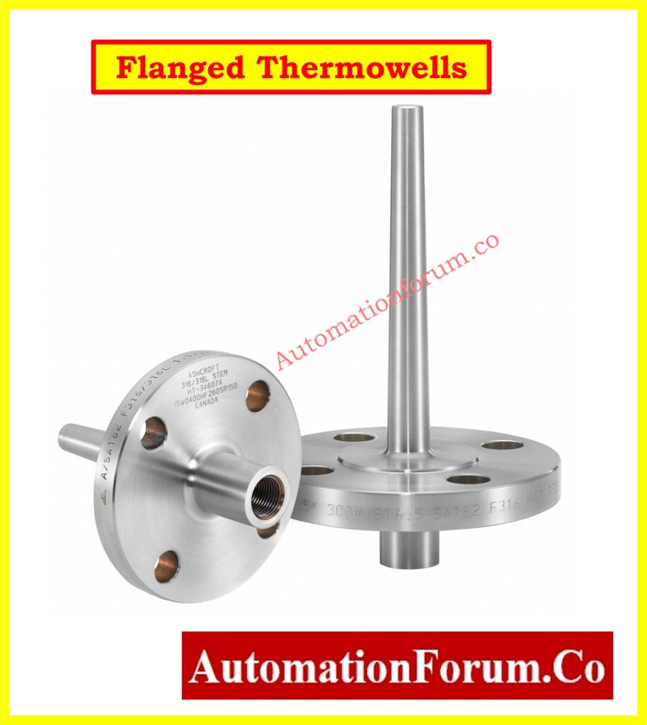
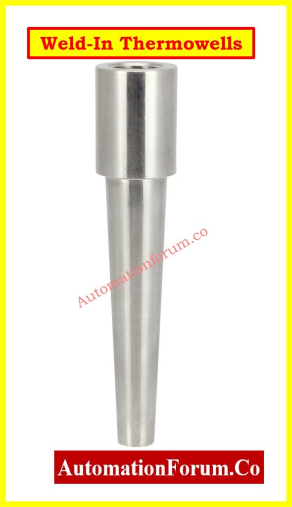
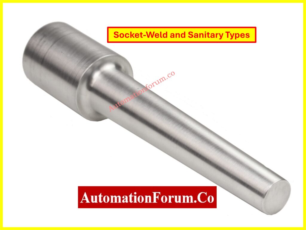
Process Connections: The way the thermowell connects to piping or vessels depends on whether it is threaded, flanged, or welded.
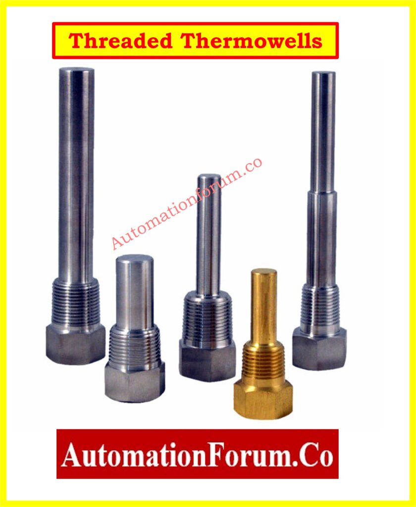
Types of Thermowells
Threaded Thermowells
inserted straight into smaller pipes with screws.
Affordable and adaptable, but not the best for high-pressure or corrosive tasks.
Flanged Thermowells
fitted with DIN or ANSI standard flanges.
Ideal for processes involving high pressure and temperature.
Simple to replace and remove.
Weld-In Thermowells
permanently welded to vessels or process pipes.
Robust and impervious to leaks, but replacement necessitates cutting and welding.
When choosing a thermowell, measuring performance and mechanical integrity must be taken into account. The methodical process that follows guarantees precise and secure selection.
1. Define Process Connection Size and Type
Finding out how the thermowell will connect to the process machinery is the first step.
Threaded (NPT): Frequently used in utility services; simple to set up.
Flanged: Complies with the face type (raised, flat, or ring-joint) and piping flange rating (150#, 300#, etc.).
Weld-In: Selected for long-term installations when preventing leaks is essential.
Socket-Weld: Strong and small, socket-weld pipes are ideal for high-pressure applications.
Sanitary Clamp: Food, beverage, and pharmaceutical systems all need sanitary clamps.
The U-dimension, also known as the insertion length, indicates how far the thermowell penetrates the process. This element is essential for mechanical stability as well as measuring accuracy.
In Pipelines: To obtain a representative fluid temperature in pipelines, the thermowell tip should preferably touch the pipe’s centerline. The insertion depth should, at the very least, be at least one-third of the internal diameter of the pipe.
In Tanks and Vessels: In tanks and vessels, 6 to 12 inches of penetration depth is usually adequate. Baffles, agitators, and other interior features should not be interfered with during placement.
Standard Lengths: Depending on the needs of the process, thermowells can be inserted into the following standard lengths: 2.5, 4.5, 7.5, 10.5, 13.5, 16.5, and longer.
Design Note: AWhile an excessively long thermowell may experience vibration, resonance, and even mechanical failure, a thermowell that is too short may result in inadequate heat transfer and erroneous temperature readings. Always check the insertion depth against the relevant standards and process circumstances.
If there are jackets or insulation, lagging extension is necessary.
Standard values: 2″ or 3″.
Customized to match insulation thickness.
For simpler access, make sure the sensor head is outside the insulation.
4. Decide on Extension Length (E)
The sensor connection head is moved away from hot process surfaces by the extension length.
Standard values: 3″ or 6″.
Beneficial for high-temperature applications like as furnaces or steam pipes.
Gives maintenance workers a safer working distance.
5. Match Sensor Length (X)
The temperature probe’s complete engagement with the thermowell is guaranteed by the sensor length, also known as the X-dimension. The sensor tip needs to be firmly in touch with the thermowell bore’s bottom in order to measure accurately. Slow response times and measurement mistakes might result from heat resistance introduced by any space between the sensor and the bore tip.
Simple calculations that change based on the type of process connection are used to determine the necessary sensor length:
Threaded / Socket-Weld Thermowells: X=U+T+E+1.5″
Flanged Thermowells: X=U+T+E+2.0″
Example: If the insertion length (U) is 7.5″, lagging extension (T) is 3″, and extension length (E) is 0, for a threaded thermowell:
X=7.5+3+0+1.5=12″
Thus, a 12″ sensor probe is required to ensure proper contact with the bore tip.
The bore diameter is the size of the hole within the thermowell where the sensor probe goes. Getting the right size for the bore is important for both accuracy and ease of installation.
0.260″ bore: The 0.260″ bore is made for ¼” RTD or thermocouple probes. This is a typical choice for precise instrumentation.
0.385″ bore: Works with ⅜″ thermometer stems or bulbs, which are usually used in bimetallic thermometers.
Engineering Note: To reduce air gaps, which function as insulators and slow down heat response, the space between the sensor and the bore should be as narrow as feasible. But there needs to be enough space for the probe to be put in and taken out easily.
Choosing the right thermowell needs careful consideration of the process parameters, the compatibility of the sensor, and the mechanical integrity. We have made a complete checklist that includes connection types, insertion lengths, bore sizes, materials, and vibration factors to make this easy.
This below free Excel tool is ready to use and helps EPC engineers, instrumentation specialists, and maintenance teams choose thermowells that are safe and accurate.
Choosing a thermowell isn’t as simple as looking through a catalog; it requires a careful study at the conditions of the process, the mechanical connections, the sensor compatibility, and the safety standards. Engineers can make sure that temperature measurements are accurate, sensors last a long time, and processes are safe by following the eight-step selection process, taking into account ASME PTC 19.3 vibration criteria, and making sure that the materials are compatible.
A carefully chosen thermowell lowers maintenance costs, cuts down on downtime, and protects both instruments and workers in tough industrial settings.
Refer the below link tot Explore 82 Essential Drawings and Documents for Instrumentation and Control Engineers
Frequently Asked Questions (FAQ) on Thermowell Selection
How to select a thermowell?
The sort of thermowell you choose will rely on the characteristics of the process (pressure, temperature, velocity, and fluid type) and whether the sensor will work with it. Engineers need to specify the type of process connection (threaded, flanged, or welded), the length of the insertion (U), the length of the lagging extension (T), the size of the bore, the shape of the shank, and the material used to make it. The goal is to find a compromise between mechanical strength, resistance to corrosion, and precision of measurements, all while following ASME PTC 19.3 vibration regulations.
How to size a thermowell?
To size a thermowell, you need to find the U length (insertion depth), bore size, and shank diameter that will fit both the sensor probe and the process pipe or vessel. For accurate readings, the tip should reach at least the centerline of the pipe (or one-third of its diameter). For boats, a penetration of 6 to 12 inches is normal. To cut down on thermal lag, the bore clearance should be as little as possible. The shank style should also be chosen based on the speed of the fluid and the possibility of vibration.
How to calculate the U length of a thermowell?
The U length is the distance from the process connection to the tip of the thermowell that the thermowell is submerged in.
In pipelines, U is the distance you need to go to be close to the pipe centerline (at least 1/3 of the pipe diameter).
In vessels, U is chosen to give enough immersion, which is commonly 6 to 12 inches.
Always think about the connection fitting, like the thickness of the flange or the thread engagement.
For example: For a 12″ diameter pipe, U must be about 6″ to get to the centerline.
Probe diameter: It must be the same size as the hole (¼″ probe → 0.260″ bore).
Length of the probe (X): Should let the thermowell tip touch it all the way (spring-loaded is best).
Temperature range and accuracy class (IEC 60751 Class A, B).
The sheath material works well with the technique.
Response time: Smaller probes and stepped or tapered wells make it faster.
What is the thermowell calculation?
The term “thermowell calculation” usually refers to the ASME PTC 19.3 TW-2016 standard, which checks to see if a thermowell design can handle flow-induced vibration, natural frequency, pressure, and stress constraints. This computation makes sure that the thermowell won’t vibrate or break when the process speed is high. During the design process, many manufacturers give you software or charts to help you do these calculations.
How to calculate heat length?
In thermowell language, “heat length” usually means the effective immersion length (U) that makes sure the temperature sensor is in the process fluid long enough to get an accurate heat transfer. You may figure it up by adding the U Length and any extra allowances for fittings or extensions.
For accurate measurements, the sensor tip should be submerged at least 10 times its diameter or reach the centerline of the pipe.
Test your Knowledge on RTD and Thermocouple Selection for Instrumentation Design Engineers
Refer the below link to Test your Knowledge on RTD and Thermocouple Selection