
- Introduction to Automated Instrument Index Generation from P&IDs
- What Is an Instrument Index in EPC Engineering?
- Why Automate Instrument Index Generation from P&IDs?
- Top Automated Instrument Index Generation Software for P&IDs
- Practical EPC Comparison of P&ID Instrument Index Automation Tools
- How to Compare Automated Instrument Index Generation Tools for EPC Projects
- How Automated Instrument Index Generation From P&IDs Works
- Practical EPC Example of Automated Instrument Index Generation
- What Should EPC Engineers Check Before Selecting Instrument Index Generation Software?
- Limitations of AI Based Instrument Index Generation From P&IDs
- Manual Instrument Index Generation vs Automated P&ID Extraction
- Integration of Instrument Index Automation With EPC Engineering Deliverables
- Engineering Standards and Conventions for P&ID Instrument Extraction
- How to Evaluate the ROI of Instrument Index Automation
- Questions EPC Engineers Should Ask Before Using AI for P&ID Instrument Extraction
- Frequently Asked Questions About Automated Instrument Index Generation
- Conclusion: Automated Instrument Index Generation From P&IDs
Introduction to Automated Instrument Index Generation from P&IDs
An instrument index is one of the most important engineering registers in an EPC project. It connects information from P&IDs with instrumentation engineering, control system design, procurement, commissioning, and plant maintenance.
Recent research has also specifically investigated AI based instrument index generation from P&IDs, including text detection, computer vision, and OCR techniques.
What Is an Instrument Index in EPC Engineering?
An instrument index is a structured register containing information about instruments used within a project.
What Information Is Included in an Instrument Index?
Typical fields include:
| Field | Typical information |
| Instrument tag | PT 101, FT 202, LIC 301 |
| Instrument type | Pressure transmitter, flow transmitter, level controller |
| Service | Process service or measurement description |
| P&ID reference | Drawing number and sheet |
| Loop number | Associated control loop |
| Signal type | AI, AO, DI, DO or other project specific classification |
| Location | Field, panel, cabinet or other location |
| Range | Measurement range |
| Engineering units | bar, degree C, m3/h and similar |
| Process connection | Connection information where available |
| Datasheet reference | Related instrument datasheet |
| Control system information | DCS, PLC or SIS information where available |
| Safety classification | SIL information where applicable |
| Remarks | Additional engineering information |
The exact fields depend on the EPC company, client specification, project tagging philosophy and engineering database.
An instrument index should not be confused with an I/O list. Not every instrument shown on a P&ID necessarily has a direct DCS, PLC or SIS I/O signal.
Master P&ID Reading Before Automating Instrument Data Extraction: Piping & Instrumentation Diagram (P&ID)
Why Automate Instrument Index Generation from P&IDs?
Problems With Manual Instrument Index Generation
Benefits of Automated P&ID Instrument Extraction
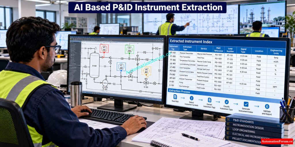
Automation can assist with initial extraction, duplicate detection, source traceability and structured output. However, engineering review remains important because P&IDs do not contain every attribute required for a complete instrument index.
For example, manufacturer information, detailed materials, calibration requirements and some control system information may exist only in datasheets, specifications, I/O databases or other engineering documents.
Refer the below link for the 82 Essential Drawings and Documents for Instrumentation and Control Engineers
Top Automated Instrument Index Generation Software for P&IDs
Common Comparison of Automated P&ID Instrument Extraction Tools
| Tool | P&ID Extraction | PDF and Scanned Drawings | Instrument Tag Extraction | Instrument Index | Other Engineering Registers | Revision and Validation | Source Traceability |
| Pathnovo | Yes | Yes | Yes | Yes | I/O, valve and equipment workflows | Yes | Yes |
| Tagsight | Yes | Yes | Yes | Yes | I/O, equipment and line lists | Yes | Yes |
| PANDID | Yes | PDF and image inputs | Yes | Structured data | Equipment and related data | Engineer verification | Yes |
| PIDVision.AI | Yes | Yes | Yes | Yes | Related engineering extraction | Review workflow | Yes |
| Novek AI | Yes | Yes | Yes | Yes | Line, equipment and engineering registers | Yes | Yes |
Connect Instrument Signals With Smarter Engineering Data Management: I/O Database
Pathnovo Instrument Index Automation
| Feature | Pathnovo Capability |
| P&ID extraction | Yes |
| Instrument tag extraction | Yes |
| Instrument type extraction | Yes |
| Service information | Yes |
| Loop information | Yes |
| Instrument index generation | Yes |
| Datasheet population | Yes |
| I/O list generation | Yes |
| Valve schedules | Yes |
| Revision tracking | Yes |
| Structured output | Excel and JSON documented |
| EPC application | Instrumentation and engineering document workflows |
Build Accurate I/O Records Without Missing Critical Signals: I/0 List
Tagsight P&ID Instrument Extraction
| Feature | Tagsight Capability |
| P&ID extraction | Yes |
| Vector PDF | Yes |
| Scanned P&ID | Yes |
| Instrument tag extraction | Yes |
| Instrument index | Yes |
| I/O list | Yes |
| Equipment list | Yes |
| Line list | Yes |
| Tag convention handling | Yes |
| Multi sheet P&ID processing | Yes |
| Source traceability | Yes |
| Engineering review | Yes |
Capture Critical Instrument Details Engineers Need For Design: Instrument Data Sheet /Specification
PANDID P&ID Data Extraction
Refer the below link
https://www.pandid.io/
| Feature | PANDID Capability |
| P&ID extraction | Yes |
| PDF and image input | Yes |
| Instrument detection | Yes |
| Tag extraction | Yes |
| Equipment detection | Yes |
| Line detection | Yes |
| Structured engineering data | Yes |
| CSV output | Documented |
| Graph based data | Documented |
| Engineer verification | Yes |
| Data correction workflow | Yes |
| Engineering relationship analysis | Yes |
Trace Every Instrument Through Complete Control Loop Documentation: Instrument Loop Diagrams
PIDVision.AI P&ID Analysis
PIDVision.AI describes AI based P&ID analysis using instrument detection, classification and OCR based extraction. Its workflow is focused on converting information contained in P&ID drawings into structured instrumentation information.
Refer the below link
https://pidvision.com/
| Feature | PIDVision.AI Capability |
| P&ID analysis | Yes |
| PDF processing | Yes |
| Image processing | Yes |
| OCR extraction | Yes |
| Instrument detection | Yes |
| Instrument classification | Yes |
| Instrument tag extraction | Yes |
| Line number extraction | Yes |
| Service description extraction | Yes |
| Instrument index workflow | Yes |
| Structured engineering information | Yes |
| Engineering review | Yes |
Avoid Cable Documentation Errors Across Complex Instrumentation Projects: Instrument Cable Schedule
Novek AI Instrument List Extraction
| Feature | Novek AI Capability |
| P&ID extraction | Yes |
| Scanned P&ID | Yes |
| PDF processing | Yes |
| Raster CAD input | Yes |
| Instrument detection | Yes |
| Instrument tag extraction | Yes |
| Instrument loop detection | Yes |
| Line number extraction | Yes |
| Process topology | Yes |
| Cross drawing connections | Yes |
| Instrument index | Yes |
| Datasheet extraction | Yes |
| Cross document reconciliation | Yes |
| Source linked review | Yes |
| Confidence based review | Yes |
| Structured engineering output | Yes |
| API integration | Documented |
| Engineering database integration | Documented |
Organize Junction Box Connections Before Commissioning Starts: Instrument Junction Box (JB) Schedule
Practical EPC Comparison of P&ID Instrument Index Automation Tools
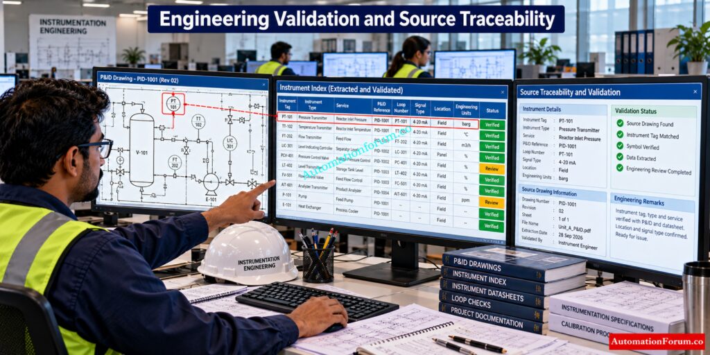
For an EPC instrumentation team, these feature tables should be used together with the common comparison table. The main evaluation should focus on whether the software can process the company’s actual P&ID formats, understand project specific tagging conventions, maintain source traceability and produce an instrument index that matches the approved engineering template.
The most important test is therefore not simply whether a tool can extract a tag from a drawing. The engineering team should verify how reliably it handles the complete workflow from P&ID extraction to structured instrument data, engineering validation, revision checking and final instrument index preparation.
Understand Systems Architecture Documents EPC Engineers Cannot Ignore: Vendor Document for Project Systems Architecture: Complete Engineering Guide for Instrumentation, Automation and Control
How to Compare Automated Instrument Index Generation Tools for EPC Projects
The feature table provides only an initial comparison. A proper EPC evaluation should examine how each system behaves with actual project drawings.
For example, two tools may both support OCR and instrument tag extraction, but their practical workflows can differ significantly when a drawing contains a crowded control loop, an unclear instrument bubble, a scanned revision or a client specific symbol.
Engineers should therefore test several representative drawing conditions, including:
- Clean vector based P&IDs
- Scanned P&IDs
- Low resolution drawings
- Drawings containing handwritten markups
- Drawings with multiple instrument loops
- Drawings using client specific symbols
- Revised drawings containing added or removed instruments
- Drawings where instrument information must be reconciled with datasheets
- Large drawing packages containing multiple process units
Strengthen Shutdown Engineering With Proper Safety Documentation: Shutdown Philosophy: Engineering Documentation for Process Safety and Emergency Shutdown Systems
Revision Comparison and Engineering Validation
The output should then be compared against the approved engineering instrument index template.
Particular attention should be given to source traceability. If an extracted instrument is recorded as PT 101, the engineer should be able to identify the exact P&ID and drawing location from which the information was obtained. This becomes especially important during engineering review, document revisions and commissioning.
Understand Electrical Power Distribution From One Critical Drawing: Single Line Diagram
Engineering Database and Excel Integration
The comparison should therefore consider the complete workflow from P&ID ingestion to extraction, validation, engineering review, structured instrument index generation and revision management rather than evaluating OCR capability alone.
No single platform should be treated as universally suitable for every EPC project. The appropriate choice depends on the drawing formats, project standards, required engineering outputs, document volumes, integration requirements, security requirements and the level of engineering validation required.
Get Ready To Use Instrumentation Engineering Documentation Templates: Downloadable Engineering Documentation Instrumentation and Control Templates
How Automated Instrument Index Generation From P&IDs Works
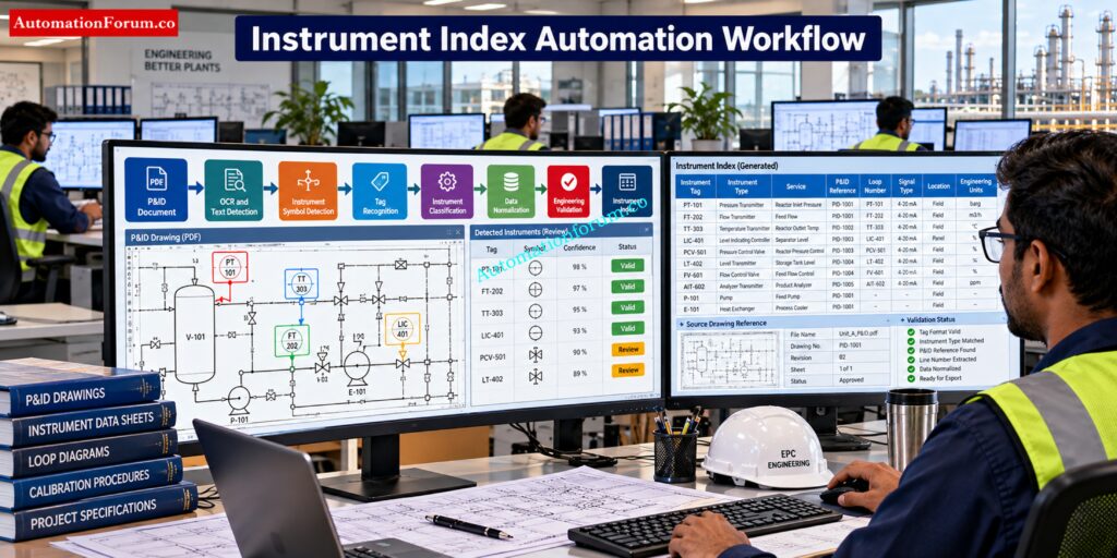
A practical automated workflow normally contains several stages.
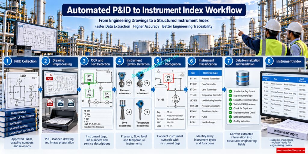
- P&ID Document Collection: The project team gathers approved P&IDs and identifies drawing numbers, revisions and document status.
- Drawing Preprocessing: PDF pages or scanned drawings are prepared for analysis. Image quality, orientation and resolution can affect extraction.
- Instrument Symbol Detection: Computer vision detects engineering items and instrument symbols.
- Tag Recognition: The system associates a detected instrument symbol with its tag.
- Instrument Classification: The extracted tag and symbol are interpreted to determine the likely instrument type.
- Contextual Relationship Analysis: The system attempts to understand relationships between instruments, process lines, equipment, valves and control functions.
- Data Normalization: Extracted information is converted into consistent fields for the project instrument index.
- Source Traceability: Each extracted record should remain traceable to its original drawing and location.
- Human Engineering Review: Engineers review uncertain records and correct exceptions before the index becomes an approved engineering deliverable.
Simply extracting text is not sufficient. A tag such as PT 101 has engineering meaning only when its symbol, location, process connection and relationship with the relevant process system are understood.
Refer the below link for the Reading and Interpreting of Piping and Instrumentation Diagrams
Practical EPC Example of Automated Instrument Index Generation
Consider a process unit containing several hundred instruments distributed across multiple P&IDs.
The major difference is therefore not that engineering review disappears. The workflow changes from repeated transcription toward verification and reconciliation.
Discover Which Engineering Documents Drive Instrumentation Design: Types of Engineering Drawings and Documents used in Instrumentation
What Should EPC Engineers Check Before Selecting Instrument Index Generation Software?
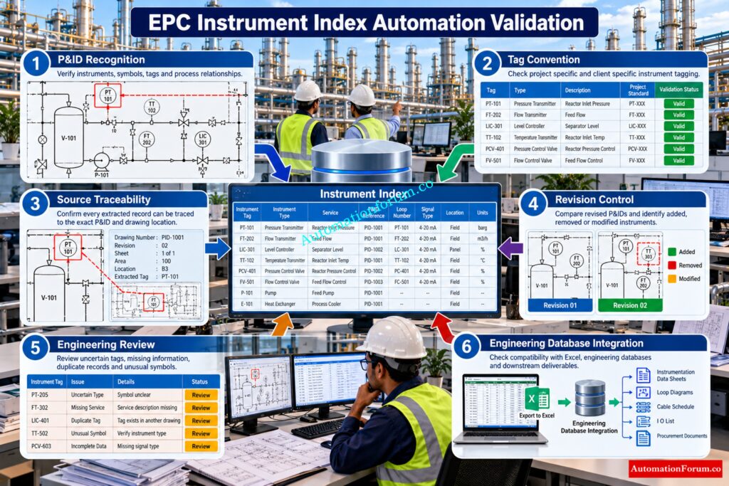
Before adopting an instrument index automation system, engineers should evaluate:
- Recognition performance on actual project drawings
- Support for scanned and low quality P&IDs
- Instrument symbol recognition
- Project specific tag convention handling
- Client specific field mapping
- Traceability to drawing and source location
- Revision comparison capability
- Excel and engineering database compatibility
- Human correction and validation workflow
- Data security and confidential project handling
- API and integration capability
- Audit trail and exception handling
A controlled pilot using representative project drawings is more meaningful than relying only on demonstrations using clean sample drawings.
Refer the below link for the Catch Critical P&ID Errors Before Design Approval: P&ID Checklist for Instrumentation Design Engineer
Limitations of AI Based Instrument Index Generation From P&IDs
AI based P&ID extraction still has practical limitations.
- Poor quality scans can affect OCR. Handwritten markups can be difficult to interpret. Overlapping symbols can create detection problems. Legacy P&IDs may use symbols and tag conventions that differ from current project standards.
- Another important limitation is missing information. A P&ID may identify a pressure transmitter and its service but not contain the manufacturer, model, complete calibration range or all datasheet information.
- False instrument detection and missed instrument detection are also possible. For this reason, engineering validation should remain part of the workflow.
ISA 5.1 provides standardized approaches for depicting and identifying instrumentation and control functions, but individual EPC companies and clients can have additional conventions. The current ANSI ISA 5.1 edition is the 2024 revision.
Define Control System Behavior Before Automation Engineering Begins: Control Narrative
Manual Instrument Index Generation vs Automated P&ID Extraction
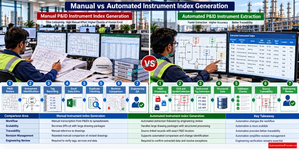
| Area | Manual workflow | Automated workflow |
| Time | Repeated drawing review and data entry | Initial extraction followed by review |
| Scalability | Becomes difficult with large drawing packages | Designed for larger document volumes |
| Consistency | Depends heavily on individual engineers | Structured extraction can improve consistency |
| Traceability | Often manually maintained | Can be linked directly to source drawings |
| Revision management | Requires repeated comparison | Some tools provide automated comparison |
| Error detection | Engineering QA checks | Automated checks plus engineering review |
| Initial setup | Low technology requirement | Requires configuration and validation |
| Customization | Direct spreadsheet control | Depends on tool capability |
| Brownfield projects | Often difficult for large archives | Useful where scanned drawing support exists |
Map Trips And Interlocks Before Final Safety Validation: Cause and Effect Drawings
Integration of Instrument Index Automation With EPC Engineering Deliverables
A reliable instrument index can become a useful source for downstream engineering activities.
These can include I/O lists, instrument datasheets, control valve schedules, shutdown valve schedules, DCS engineering, PLC engineering, SIS engineering, marshalling information, junction box schedules, cable schedules, loop diagrams, procurement records and commissioning databases.
The value increases when extracted records remain traceable to the original P&ID and can be reconciled with datasheets, cause and effect documents and other engineering registers.
See How Process Engineers Map Complete Plant Processes: Process Flow Diagram
Engineering Standards and Conventions for P&ID Instrument Extraction
- ISA 5.1 Instrumentation Symbols and Identification: ISA 5.1 is important when interpreting instrumentation symbols and identification methods.
- ISA 20 Instrument Specification Forms: ISA also maintains ISA 20 specifications covering forms for process measurement and control instruments.
- IEC 61511 and IEC 61508 for Safety Instrumentation: IEC 61511 and IEC 61508 can become relevant when safety instrumentation and SIL information are involved.
Client P&ID Standards and Project Tagging Philosophy: Client engineering specifications and the project tagging philosophy remain equally important.
An automated tool should not be assumed to guarantee compliance with any engineering standard simply because it recognizes standard symbols.
Document PLC Alarms And Trips Before Plant Commissioning: PLC Alarm and Trip Documentation Procedure – EPC PLC Automation Engineer Guide
How to Evaluate the ROI of Instrument Index Automation
A practical EPC evaluation can use:
Manual engineering cost =
Number of P&IDs × average instruments per P&ID × average review and entry time per instrument × engineering hourly cost
Then compare this with:
Automation software cost + implementation cost + validation hours + revision processing effort
Potential rework avoided can also be considered.
The actual business case depends on project size, drawing quality, automation capability, engineering review requirements and integration depth.
Build Complete PLC Records For Reliable Automation Projects: PLC System Documentation Guide: Essential Records for Industrial Automation
Questions EPC Engineers Should Ask Before Using AI for P&ID Instrument Extraction
- Can the system process scanned P&IDs?
- Can every extracted tag be traced to the source drawing?
- How are uncertain results presented?
- Can engineers manually correct extracted information?
- Can the output match our existing instrument index template?
- Can the system compare P&ID revisions?
- Can it recognize our client specific symbols and tag conventions?
- How is confidential project information protected?
- Can extracted data be integrated with our existing engineering systems?
Compare Powerful P&ID Platforms Used For Process Engineering: 11 Best P&ID Software Tools for Process Design Engineers in 2025
Frequently Asked Questions About Automated Instrument Index Generation
What is an Instrument Index?
What is the difference between PID and P&ID?
In process engineering, most people call P&ID Piping and Instrumentation Diagram and PID Process Identification or other project specific terms. A P&ID shows process equipment, piping, valves, instruments and control relationships used for plant design and operation.
What is a P&ID diagram in instrumentation?
What is the best software for creating P&IDs?
The choice of P & I D software should be based on project standards, symbol libraries, interface with engineering databases, and collaboration and document management needs.
Common engineering platforms include AutoCAD Plant 3D and AVEVA and Hexagon solutions, however appropriateness depends on the EPC project.
What is the ISO standard for P&IDs?
ISO 10628 is an international standard for diagrams for the chemical and petrochemical sector comprising the graphical representation of process plants.
Additional ISA standards and client specific P&ID conventions may be defined as per project requirements.
Which software is used for P&ID?
EPC businesses develop and maintain P&IDs by using specialist engineering platforms like AutoCAD Plant 3D, AVEVA and Hexagon tools.
The choice of software is usually dictated by client standards, project database and engineering workflow.
What software can I use to create a P&ID?
You can utilize specialized P&ID engineering tools like AutoCAD Plant 3D or other plant design platforms used by EPC businesses.
For professional projects, check symbol standards, data management, collaboration and compatibility with the client’s engineering system.
What is the best free software for creating P&IDs?
Free P&ID tools can be useful for learning, basic diagrams and small engineering exercises.
For EPC projects, engineers generally need controlled symbols, engineering data management, revision control and project specific standards.
Which AutoCAD is best for P&ID?
The final choice should be based on the client’s necessary software platform and engineering requirements for an EPC project.
What is automated instrument index generation from P&IDs?
Automated instrument index generation uses OCR, computer vision, AI and engineering rules to extract instrument information from P&IDs.
The extracted information can then be structured into an instrument index for engineering review and validation.
Can AI generate an instrument index from a PDF P&ID?
The index extracted has still to be validated by an instrumentation engineer before being entered into an approved engineering registry.
What information can AI extract from a P&ID?
What is the difference between OCR and P&ID understanding?
OCR mainly converts text in a drawing into machine readable information.
P&ID understanding also interprets symbols, relationships, process lines, equipment and engineering context.
Can automated tools generate I/O lists from P&IDs?
Some automated engineering platforms provide I/O extraction or I/O list generation workflows from P&IDs.
However, a complete approved I/O list may require information from control system engineering and other project documents.
Can AI tools handle scanned P&IDs?
Some specialized P&ID analysis tools support scanned drawings and image based documents.
Extraction quality can still depend on resolution, drawing condition, OCR quality and project specific symbols.
How accurate is automated instrument index generation?
Accuracy depends on the software, P&ID quality, drawing complexity, tagging conventions and engineering configuration.
Vendor accuracy claims should be validated using representative project drawings before production use.
Does an automated instrument index still require engineering review?
Learn Exactly What A Complete Instrument Register Contains: Instrument Index: Definition, Example, Template and How to Create One
Conclusion: Automated Instrument Index Generation From P&IDs
Automated instrument index generation from P&IDs can change an EPC workflow from extensive manual transcription toward structured extraction, validation and reconciliation.
The appropriate solution depends on project size, P&ID quality, engineering standards, required output, integration requirements, data security, validation workflow and revision management.
https://automationforum.co/instrument-index-generator/For instrumentation engineers, the most important evaluation criterion is not simply whether a tool can read a tag. The practical question is whether the system can produce traceable engineering data that fits the project workflow and can be confidently reviewed before becoming an approved deliverable.
Refer the below link for the Instrument Index Generator for EPC Instrumentation Projects
