- What is the control narrative?
- Detailed Explanation of Control Narrative
- What is the purpose of a control narrative?
- What is included in Control Narrative?
- Best Practices for Creating Control Narratives
- Control Narrative vs Cause & Effect Matrix
- Industry Standards & Guidelines for Control Narratives
- Frequently Asked Questions: Control Narrative in Engineering Project Documentation
What is the control narrative?
A system control philosophy is a document that contains a description of the operating philosophies prepared by process engineers.
The control narrative describes the control philosophy as well as the variables in the control program. Field instrument parameters, pumps, valves, and other process equipment status signals are examples of variables.
Detailed Explanation of Control Narrative
A statement of the main operating principles is found in a document called a system control philosophy. The Control Narrative describes the control philosophy and identifies the control program’s variables. Alarm set points and shutdown values are typically described in control narratives.
The control narrative specifies the conditions for the system’s programming. The Control Narrative explains the plant operation philosophy and variables to be involved in the control program. Variables include field instrument parameters, pump, valve, and other equipment status signals, and field instrument, equipment, and smart safety relay information. A control philosophy improves definitions, concepts, and procedures during design and implementation.
What is the purpose of a control narrative?
Most of the time control narratives are used for three reasons. Control narratives provide:
- Process engineers have the chance to set out and record operational procedures on the plant floor.
- Documentation for operator training and comprehension of the process’s equipments, variables, For all processes, the control narrative should always be included in the skill block handbook and new operator training materials.
- A starting point for control system programmers to write configuration code for the control system that will control the process, even if they have little experience with that particular process.
Overall, the purpose of a control narrative is to provide a comprehensive understanding of the process and its performance, which in turn can be used as a base to develop control logics for DCS/PLC systems by automation engineers.
What is included in Control Narrative?
A Control Narrative includes:
- Process Overview: Basic description of the overall system process, including its purpose, process timeline by functional unit, major functional unit descriptions, basic description of the subsystem process, and how it works with utilities.
- Equipment List: A complete list of all the physical equipment used in the process. Some of these are motors, valves, transmitters, and so on.
- Software Components: Non-physical devices that are involved in the process. Control loops, totalizers, calculations, and parameters are examples of these.
- Alarms: All non-default alarms linked with the process are defined here. These alarms will be shown in a number of places on the user interface.
- Process Functionality Description (Interlock and sequence): Sequence descriptions are step-by-step procedures that explain how the unit works.
A. Sequence Area
1. Sequence Set Points
a. Sequence Steps
Interlocks are any corrective actions that are meant to protect the product, people, or equipment.
Concurrent Tasks: A definition of all normal process control functions that work independently of the sequences.
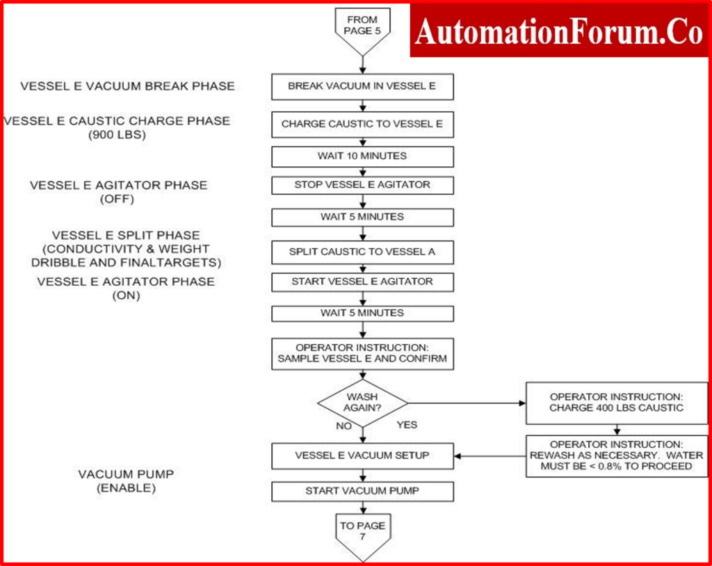
The chart below is an example of a control narrative chart.

Best Practices for Creating Control Narratives
Purpose of Control Narratives and Recommended Approach to Control Narratives
- Document the intent and rationale behind control configurations, complementing technical design documents that describe the implementation details.
- Provide a clear reference for programming, troubleshooting, and validating system behavior.
Types of Documentation
- Parameter List
- Use a structured format (e.g., spreadsheet) to include key information such as module names, I/O details, alarm settings, and tuning constants.
- Include a notes section for describing simple logic or operational behaviors.
- Detailed Logic Descriptions
- Provide concise explanations for complex control logic, such as interlocks, cascading, or ratio controls.
- Cross-reference these descriptions with the parameter list for consistency.
- Process Flow Diagrams
- Create flow diagrams for individual control phases or sequences, detailing parameters, logic paths, and failure modes.
- Develop flowcharts for operational workflows to show how phases interact and parameters are passed between them.
Development Process
- Begin with a high-level process description from the relevant process owner or engineer.
- Gradually expand into a detailed functional specification, documenting:
- Normal operational sequences.
- Control logic responsibilities (e.g., system vs. operator actions).
- Expected responses to specific inputs and failure scenarios.
Structure and Format
- Use a modular approach to ensure clarity and reusability.
- Maintain a consistent structure across documents to improve readability and ease of use.
- Incorporate visuals (e.g., flowcharts, diagrams) to enhance understanding of complex logic.
Stakeholder Involvement
- Include input from all relevant stakeholders, such as process engineers, operators, and maintenance teams.
- Use accessible language to ensure non-technical stakeholders can understand the logic without specialized knowledge.
Standards to Guide the Process
- Follow industry-recognized standards to ensure completeness and compatibility with broader system requirements.
- Use these standards to define: The level of detail required in the narrative, Key elements like sequence descriptions, responsibilities, and exceptions.
Control Narrative vs Cause & Effect Matrix
| Aspect | Control Narrative | Cause & Effect Matrix (C&E Matrix) |
| Format | Written document with structured text, tables, or flowcharts. | A table that shows the causes (inputs) and effects (outputs). |
| Purpose | This explains how the control system works, including logic, interlocks, and alarms. | It tells you what safety or process steps to take when certain things happen. |
| Scope | This includes normal operation, starting up, shutting down, alerts, and contacts with operators. | Concentrates on unusual situations, travels, and safety shutdowns. |
| Level of Detail | Gives a story-based explanation of the order of events and how they fit together. | A short map of the relationships between inputs and outputs. |
| Use Case | A guide for programmers (PLC/DCS), operators, and trainees. | Safety system testing (SIS/ESD), FAT/SAT validation reference. |
| Audience | Engineers who work on processes, automation, and operations. | Engineers in charge of safety, control, and commissioning. |
| Example | “If the tank level is less than 20%, the pump stops and a low-level alarm goes off.” | Cause: When the tank level falls below 20%, the pump turns off and the alarm turns on. |
Industry Standards & Guidelines for Control Narratives
Following known criteria while writing control narratives makes sure that projects are clear, safe, and consistent:
- Functional Requirements (ISA-5.06.01) Documentation sets rules for how to write down the functional specifications of control systems, such as how to show logic and sequences.
- ISA-88 and ISA-106 are standards for batch and procedural automation.
- Give a structure for writing down batch and procedural operations, such as phases, sequences, and control modules.
- IEC 61511 Functional Safety (SIS Design) sets safety lifecycle requirements for process industries. It makes sure that control narratives’ interlocks, trips, and shutdowns are in line with SIS safety standards.
- Templates and standards that are specific to your company
Many companies, including Shell DEP and ExxonMobil Engineering Standards, offer their own templates that make sure that control narratives across projects have the same format, structure, and language.
Frequently Asked Questions: Control Narrative in Engineering Project Documentation
What is a Control Narrative Philosophy?
The control narrative philosophy outlines the operating principles and key variables of a control program. It provides context for how automation and processes are designed to function, typically including:
- The control narrative, which details programming conditions and the system’s expected behavior.
- The plant’s operation philosophy, explaining how processes should align with broader operational goals.
- Specifications such as alarm set points and shutdown values, ensuring safe and efficient operation.
What is a Control Narrative Document?
The control narrative document is a formal description of how a process and its automation systems are expected to function. It serves as a bridge between the process design and the control system implementation, offering:
- A clear explanation of the process behavior and automation logic.
- Comprehensive guidance for system programmers and operators.
- A way to address gaps caused by insufficient documentation or comments in the code.
What Does Control Narrative Mean in Project Documentation?
A control narrative in engineering documentation specifies how the control system should operate under various conditions. It translates the high-level process requirements into operational logic, enabling consistent implementation and testing. Key elements include:
- Descriptions of process behavior.
- Expected system responses to various inputs and scenarios.
- Integration with broader operational objectives.
What is the Difference Between a Functional Description and a Control Narrative?
The functional description and control narrative serve different purposes in system documentation:
| Aspect | Control Narrative | Functional Description |
| Purpose | High-level overview of system functionality. | Detailed specification of system design. |
| Focus | Operational philosophy and expected outcomes. | Technical details for implementation. |
| Detail Level | Conceptual and general with some specific details. | Comprehensive and highly detailed. |
| Audience | Engineers, operators, and non-technical stakeholders. | Programmers, system designers, and testers. |
| Content | Describes process behavior and system responses. | Includes logic diagrams, parameter settings, and I/O relationships. |
| Use Case | Provides context and guidance for system understanding. | Serves as a blueprint for precise system configuration. |
| Examples | Expected operation sequences.Alarm and shutdown points | Logic flowcharts.Tuning constants and parameter lists. |
What is a controlled narrative?
A controlled narrative, also known as a control narrative, is a document that tells you how a process or piece of equipment should work in different situations. It explains the control philosophy, logic, interlocks, alarm handling, and operator actions so that both engineers and operators know how the system should work.
What does a control narrative look like?
Structured language, flowcharts, or tables are common ways to write a control narrative. It has:
- Process overview
- Control modes (manual, auto, emergency)
- Startup/shutdown sequences
- Interlocks and permissives
- Alarm and trip functions
- Operator-HMI interactions
For instance, “If the compressor discharge pressure is greater than 8 bar, the recycle valve should open on its own until the pressure drops below 7.5 bar.”
What is the difference between functional description and control narrative?
- Functional Description: A high-level overview of the system’s goals and what needs to be done to reach them.
- Control Narrative: A detailed explanation of how certain goals are met through sequences, alerts, and interlocks.
In short, a functional description tells you what something is and a control narrative tells you how to use it.
What is a control system in instrumentation?
A control system in instrumentation is a set of field instruments, sensors, actuators, and controllers (PLC/DCS) that keep an eye on process variables like flow, pressure, temperature, and level and make changes to them automatically to keep the process stable, safe, and efficient.
What is a control narrative?
A control narrative is the same as a controlled narrative. It is a full written description of process control logic that is the basis for designing, developing, and training operators for automation systems.
What are the 7 characteristics of narrative?
This comes from normal tale writing but works here:
Perspective: Written from the control system’s operational viewpoint.
Structure: Startup, operation, shutdown.
Actors: Instruments, control systems, operators.
Setting: Process environment.
Conflict: Upsets, trips, abnormal events.
Resolution: Automated or manual corrective actions.
Purpose: Safety, efficiency, reliability.