Basics of P&ID (piping and instrumentation diagram)

What is P & ID?
A Process and Instrumentation Diagram (P & ID) shows the process flow and interconnection of process equipment which is used control a process. The P & ID includes every mechanical aspect of the plant except stream flows, pipe routing, pipe lengths, pipe fittings, supports, structure & foundations.
A P&ID provides information to begin planning for construction of plant. There are different Sets of symbols are used to depict mechanical equipment, piping, piping components, valves, drivers and instrumentation and controls. A P&ID digram contains following information regarding the equipment: size, rating, throughput, and utility usage.
Uses of P & ID:
- Used for planning & construction of plant
- Used to operate the process
- Used for maintenance & modification of the process
- Used by mechanical technicians & safety personnel
- Used for HAZOP study of plant
- The controlled document formally issued at various stages of the project
How to create a P&ID?
Different software is available to create or draw a P&ID diagram. Only a few steps to follow to create a p&id diagram, but one who does it should know well knowledge about the plant process.
- Create the full list of instruments and equipment required for the process. Check the symbols used for each equipment from the library.
- Arrange all equipment in the process order and do the connection.
- Then review the details with a trusted colleague. Walk through the process several times and search for inefficiencies.
- Discuss with the collates
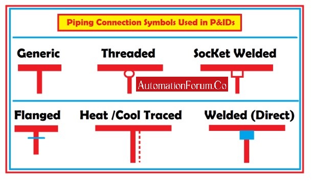
P&ID symbols and abbreviations:
Process lines:

Instrument Bubbles:

Process equipents:

Valve types:

VS — Gate Valve
VD — Globe, Needle or Angle Valve
VR — Plug Valve
VB — Ball or 3-way Plug Valve
VDR — Check Valve
VF — Butterfly Valve
VM — Diaphragm Valve
VP — Piston Valve
Temperature:
These symbols are represented in the respective instrument bubbles:
TE = Temperature sensing element
Th = Thermometer Indicator
TRC = Recorder-controller
TR = Recorder
Pressure:
These symbols are represented in the respective instrument bubbles:
PC = Controller
PI = Indicator
PIC = Indicator-controller
PR = Recorder
Level:

LC = Controller
LG = Glass
LI = Indicator
LR = Recorder
Flow:

FC = Controller
FE = Test orifice plate
FI = Indicator
FR = Recorder
How to read a P&ID?
Each instrument in the process and their connections are drawn in a P&ID diagram. Thus the process is simply described in the diagram. Specification of the instruments is written with the instrument symbol. The specification of the line is code in the line or above the line as shown in the below picture:

Area Code:
01 : Urea
02 : Reforming Section
03 : CO2 absorption Section
04 : Synthesis gas compression
05 : Ammonia Synthesis
06 : Steam Generation
07 : Power Generation
08 : CW circulation
Fluid Type:
KS : Very High-Pressure Steam
HS : High-Pressure Steam
LS : Low-Pressure Steam
P : Process Fluid
IA : Instrument Air
UA : Utility Air
UN : Utility Nitrogen
Material:
1 : Carbon Steel
3 : Austenitic Stainless Steel
4 : Reinforced Thermal Resin Pipe
5 : Si Killed Carbon Steel or CrMo steel
6 : Ferritic Alloy Steel
7 : Cast Steel
8 : Austenitic SS or Ferritic Alloy Steel
9 : Urea Grade SS
Material Rating:
1 : 150#
3 : 300#
5 : 600#
6 : 900#
7 : 1500#
8 : 2500#
9 : Special
Insulation Specification:
N : Not Painted /Insulated
PP : Personnel Protected
S : Internal Treated/External Painted
A : Internal Treated, External coated
B : External Coated
E : Electric traced
F : Cold Insulated
I : Hot Insulated
T : Steam traced
V : External painted
W : Jacketed


