
- Introduction
- What Are Ex d and Ex ia Protection?
- How Does Ex d Protection Work?
- How Does Ex ia Protection Work?
- EX d vs EX ia: Key Differences
- When to Choose Ex d or Ex ia
- When to Choose Ex ia Protection?
- When to Choose Ex d Protection?
- When Ex ia Is Usually More Attractive
- When Ex d Is Usually More Attractive
- Ex d vs Ex ia: How to Choose the Right Protection
- Ex d vs Ex ia for Hazardous Area Zones
- Ex d vs Ex ia for Process Instrumentation
- Practical Example of Selecting Ex d or Ex ia
- Important Parameters to Check Before Selecting Ex d or Ex ia
- Common Mistakes When Selecting Ex d and Ex ia Equipment
- Troubleshooting Ex d and Ex ia Systems
- Best Practices for Choosing Ex d or Ex ia
- Which Is Better: Ex d or Ex ia?
- Frequently Asked Questions about EX d vs EX ia: Choose the Right Protection
- What is the difference between flameproof and intrinsically safe equipment?
- What is the difference between Ex d and Ex i?
- What is the difference between ATEX and intrinsically safe?
- What is Class I Division 2 intrinsically safe?
- What are Class I, II, and III hazardous locations?
- What is Class I Division 2 Group D?
- What is Class I Zone 2 hazardous area?
- What are Class II hazardous materials?
- What is Class I hazardous area?
- What is the main difference between Ex d and Ex ia?
- Is Ex ia safer than Ex d?
- Can Ex ia equipment be used in Zone 0?
- Can Ex d equipment be used in Zone 1?
- When should Ex d be selected?
- When should Ex ia be selected?
- What parameters should be checked before selecting Ex ia?
- Can Ex d and Ex ia be used in the same process plant?
- EX d vs EX ia: Choosing the Right Hazardous Area Protection
Introduction
EX d vs EX ia in Hazardous Area Instrumentation
Selecting the correct explosion protection method is an important part of instrument selection in oil and gas, petrochemical, chemical, refining, LNG and other process plants. Ex d and Ex ia are not simply two alternative labels for the same equipment. They use fundamentally different protection principles.
Ex d relies on a certified enclosure that can contain an internal explosion and prevent flame from reaching the surrounding atmosphere. Ex ia limits electrical and thermal energy so that ignition cannot occur within the defined fault conditions.
The correct choice depends on hazardous area classification, equipment characteristics, electrical parameters, certification, installation method, maintenance philosophy and project requirements. The certificate and actual equipment marking must always be checked before final selection.
What Are Ex d and Ex ia Protection?
Both Ex d and Ex ia are protection concepts used for equipment operating in explosive atmospheres, but they address the ignition risk differently.
What Does Ex d Mean?
Ex d means flameproof enclosure protection. The equipment is contained inside an enclosure designed to withstand an internal explosion. The enclosure and its flame paths prevent the resulting flame from igniting the surrounding atmosphere.
What Does Ex ia Mean?
Ex ia means intrinsic safety with the highest protection level within the Ex i family. Instead of containing an explosion, intrinsic safety controls the electrical and thermal energy available in the circuit. The objective is to prevent sparks, arcs and hot surfaces from becoming capable of igniting the surrounding atmosphere under the specified conditions.
Difference Between Ex d and Ex ia Protection
This difference is the foundation of the EX d vs EX ia selection decision. Ex d controls the consequences of an internal ignition, while Ex ia controls the energy that could cause ignition.
Stop Grounding Mistakes Before They Cause Instrument Failures: Single Point vs Multiple Point Grounding in Instrumentation Systems: Complete Guide for Engineers
How Does Ex d Protection Work?
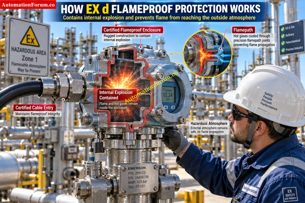
How Flameproof Ex d Enclosure Protection Works
Ex d protection uses a specially designed flameproof enclosure. If an ignition occurs inside the enclosure, the enclosure must withstand the resulting pressure and prevent flame propagation into the surrounding hazardous atmosphere.
Role of Flamepaths in Ex d Protection
The flame path is an important part of this protection concept. Joints between enclosure components are designed with controlled dimensions so that hot gases escaping from an internal event are sufficiently cooled before reaching the external atmosphere.
Avoid Certification Confusion When Selecting Hazardous Area Equipment: ATEX vs IECEx Certification: Complete Guide for Hazardous Area Instrumentation
Ex d Cable Gland and Cable Entry Requirements
For this reason, an Ex d installation is not simply a matter of purchasing an enclosure with an Ex marking. Cable entries, glands, covers, fasteners, flame paths and installation practices must remain within the certified configuration.
Practical Example of Ex d Instrumentation
For example, an Ex d pressure transmitter installed near a hydrocarbon processing unit may be selected where the instrument electronics require an enclosure based protection concept. The engineer must verify the certificate, gas group, temperature class, equipment protection level, ambient conditions and approved cable entry arrangement before installation.
IEC material identifies flameproof protection as a protection concept that depends on quenching of flame through the enclosure design.
Refer the below link for the Junction Box Load Calculator
How Does Ex ia Protection Work?
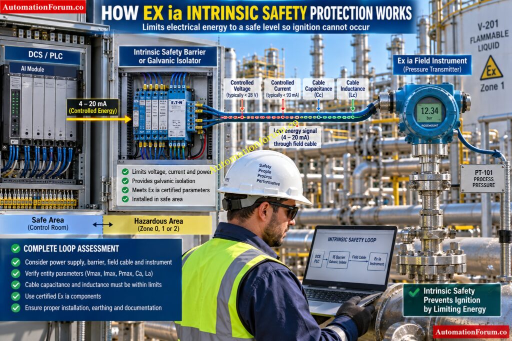
How Intrinsic Safety Ex ia Protection Works
Ex ia protection takes a different approach. The electrical energy available to the hazardous area circuit is restricted so that the circuit cannot create an ignition source within the specified operating and fault conditions.
Role of Voltage Current and Power in Ex ia
Voltage, current, power, capacitance and inductance are important considerations. Stored energy in capacitors and inductors also needs to be considered during intrinsic safety assessment.
Intrinsic Safety Barrier and Galvanic Isolator
A typical Ex ia instrumentation loop may include a control system, an intrinsic safety barrier or galvanic isolator, field cable and an Ex ia transmitter. The complete circuit has to be assessed rather than looking only at the field instrument.
Ex ia Entity Parameters
Entity parameters can include values such as maximum input voltage, current and power together with internal capacitance and inductance. These values must be compatible with the associated apparatus and field wiring.
Practical Example of Ex ia Instrumentation
For example, a pressure transmitter with an Ex ia certification may be connected through a suitable galvanic isolator. The engineer must verify the output parameters of the associated apparatus against the input parameters of the field instrument and also consider cable capacitance and inductance.
This is why intrinsic safety is particularly useful for measurement and control circuits. It can provide hazardous area protection without requiring every field device to depend on a heavy flameproof enclosure.
IEC 60079 identifies intrinsic safety as a protection concept based on limitation of energy, while IEC 60079 also addresses the relevant equipment and system requirements.
Master Hazardous Area Installation Rules Before Site Commissioning: IEC 60079-14 Explained: Complete Guide to Hazardous Area Installation for Instrumentation and Control Systems
EX d vs EX ia: Key Differences
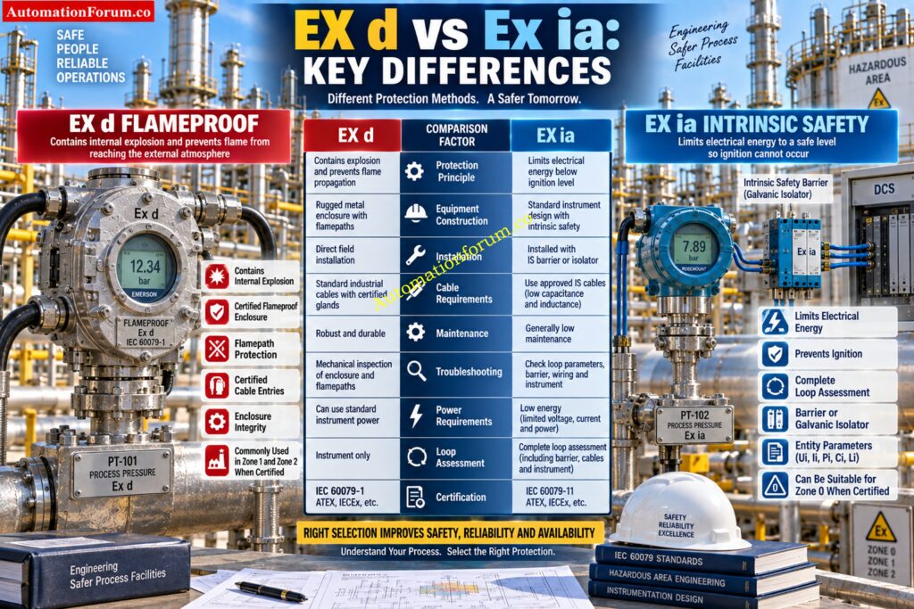
| Engineering consideration | Ex d | Ex ia |
| Protection principle | Contains an internal explosion | Limits energy to prevent ignition |
| Equipment construction | Certified flameproof enclosure | Energy limited electrical circuit |
| Energy limitation | Not the primary protection principle | Fundamental to protection |
| Typical instrumentation | Transmitters, switches, local equipment and higher power devices | Transmitters, sensors and measurement circuits |
| Zone suitability | Commonly Zone 1 and Zone 2 when certified | Can be suitable for Zone 0, Zone 1 and Zone 2 when certified |
| Installation | Requires careful enclosure and entry installation | Requires complete loop verification |
| Cable and gland considerations | Certified entries and suitable glands are important | Cable characteristics form part of the intrinsic safety assessment |
| Maintenance | Enclosure integrity must be preserved | Circuit parameters and segregation must be maintained |
| Troubleshooting | Focuses on enclosure, flame paths and entries | Focuses on circuit energy, barriers and parameters |
| Barrier requirement | Normally not required solely because of Ex d | Associated apparatus is normally required for an Ex ia circuit |
| Loop considerations | Mainly installation and certified assembly considerations | Complete circuit compatibility is fundamental |
| Certification | Equipment certificate and installation conditions must be checked | Equipment and associated apparatus compatibility must be checked |
| Installation complexity | Often higher mechanical installation requirements | Often higher electrical design and documentation requirements |
| Main advantage | Suitable for equipment requiring enclosure based protection | Excellent for low energy instrumentation circuits |
| Main limitation | Heavier equipment and greater enclosure installation requirements | Limited energy availability and more detailed loop verification |
The comparison should not be interpreted as one method being universally better. The correct protection concept depends on the application and certified equipment.
Choose The Right Ex Zone Cables Without Costly Mistakes: What Cables to Use in Ex Zones: Complete Guide for Instrumentation & Control Engineers
When to Choose Ex d or Ex ia
The practical question for an instrumentation engineer is not simply whether Ex d or Ex ia is better. The real question is which protection concept fits the instrument, hazardous area, electrical circuit and installation philosophy.
Protect Ex Instrument Loops With The Right Cable Selection: Intrinsically Safe Cables for ATEX Zones – Complete Checklist for EPC Engineers
When to Choose Ex ia Protection?
When Is Ex ia Suitable for Process Instrumentation?
Choose Ex ia when the instrument can operate within the permitted intrinsic safety energy limits and the complete circuit can be properly assessed.
Ex ia is often a good choice for low energy instrumentation such as pressure transmitters, differential pressure transmitters, temperature transmitters, level transmitters and other measurement circuits.
When to Choose Ex ia for Low Energy Instrument Circuits
Ex ia can be particularly attractive when the instrument is installed in a Zone 0 application and the equipment certification specifically permits that use.
Choose Ex ia when:
- The field instrument has suitable Ex ia certification.
- The hazardous area classification requires the applicable level of protection.
- The instrument operates with limited voltage, current and power.
- A suitable intrinsic safety barrier or galvanic isolator is available.
- The field device and associated apparatus have compatible parameters.
- Cable capacitance and inductance can be maintained within the permitted limits.
- The project instrumentation philosophy favors intrinsic safety.
- Maintenance requirements favor an energy limited instrumentation circuit.
For example, a two wire pressure transmitter connected to a control system through a suitable galvanic isolator can be an excellent application for Ex ia when the complete loop satisfies the applicable intrinsic safety requirements.
The important point is that the instrument alone does not make the system intrinsically safe. The field device, associated apparatus and interconnecting cable must be considered together.
Understand Intrinsic Safety Levels Before Designing Hazardous Loops: Intrinsic Safety Protection Systems: Understanding Ex ia, Ex ib, and Ex ic
When to Choose Ex d Protection?
When to Choose Ex d for Higher Power Equipment
Choose Ex d when the equipment requires a flameproof enclosure based protection concept and the certified equipment is suitable for the hazardous location.
Ex d can be practical for equipment with higher power requirements or equipment where an enclosure based protection method is appropriate.
Master Critical Functional Safety Terms Every Engineer Needs: Functional Safety Terminology – Excel Download for Industrial Automation
When to Choose Ex d for Flameproof Equipment
Choose Ex d when:
- The equipment has suitable Ex d certification.
- The hazardous area classification permits the certified equipment.
- The equipment power requirement is not convenient for an intrinsic safety arrangement.
- The equipment construction is better suited to a flameproof enclosure.
- A suitable certified cable entry arrangement is available.
- The installation can maintain the certified flameproof enclosure integrity.
- The project specification accepts the Ex d protection concept.
- Maintenance personnel can inspect and maintain the equipment according to the applicable requirements.
For example, an electrical device installed in a Zone 1 hydrocarbon processing area may use Ex d protection where its construction and power requirements make enclosure based protection suitable.
However, selecting Ex d does not remove the need for careful installation. Cable glands, unused entries, enclosure covers, flame paths and mechanical integrity must remain suitable for the certified arrangement.
Prevent Hazardous Area Failures With Proper Gland Selection: Cable Gland Selection for Hazardous Area Installations – Complete 2025 Guide
When Ex ia Is Usually More Attractive
Ex ia is usually more attractive when the application involves low energy measurement and control circuits.
A typical example is a field transmitter connected to a DCS or PLC through an intrinsic safety barrier or galvanic isolator. The circuit can be designed around defined voltage, current, power, capacitance and inductance limits.
This can simplify the physical field installation because the protection philosophy is based primarily on limiting energy rather than containing an internal explosion.
However, the electrical design and documentation require careful attention. Incorrect barrier selection or failure to verify entity parameters can invalidate the intended protection arrangement.
Know Which Cable Type Your Intrinsic Safety Loop Requires: Difference Between Intrinsically Safe (IS) and Non-IS Cables
When Ex d Is Usually More Attractive
Ex d is usually more attractive when the equipment requires greater electrical power or when the equipment is designed around a flameproof enclosure.
It can also be useful for equipment where an intrinsic safety circuit is not practical.
The mechanical installation becomes especially important. The enclosure, cable entries and flame paths form part of the protection concept, so installation quality directly affects the effectiveness of the protection method.
Verify Intrinsic Safety Loops Before Approving Field Instruments: Intrinsic Safety Entity Parameter Calculator for Reliable Hazardous Area Loop Design
Ex d vs Ex ia: How to Choose the Right Protection
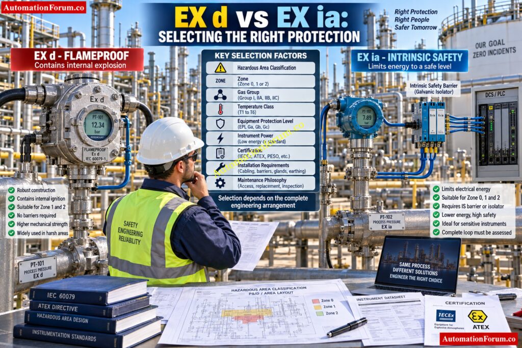
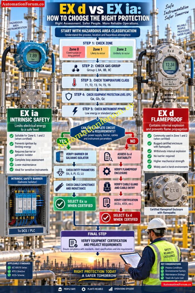
A practical selection sequence is:
Start with the hazardous area classification: Check the Zone, gas group, temperature class and required equipment protection level.
Check the instrument: Determine the instrument type, power requirement, signal type, voltage and current requirements.
Check the certification: Confirm that the actual equipment certificate and marking support the intended application.
Evaluate Ex ia: If the instrument is suitable for intrinsic safety, verify the associated apparatus and complete loop parameters.
Evaluate Ex d: If intrinsic safety is not suitable or the equipment is designed for flameproof protection, verify the enclosure certification and installation requirements.
Check the project philosophy: Confirm the selected method against the project specification, hazardous area philosophy, inspection requirements and maintenance strategy.
This approach is more reliable than simply asking whether Ex d or Ex ia is safer. The correct question is whether the selected protection concept remains valid for the complete installation.
Check Barrier Fault Currents Before Energizing IS Circuits: IS Barrier Earth Fault Current Calculator | Intrinsic Safety Loop Design Tool
Ex d vs Ex ia for Hazardous Area Zones
Hazardous area classification is one of the first inputs for equipment selection.
Zone 0 describes an area where an explosive gas atmosphere is present continuously, for long periods or frequently. Zone 1 describes an area where such an atmosphere is likely to occur during normal operation. Zone 2 describes an area where it is not likely during normal operation and, if it occurs, exists only for a short period.
An Ex ia device can be suitable for Zone 0 when its certificate and marking provide the required suitability. Ex d equipment is commonly used in Zone 1 and Zone 2 applications when its certification permits the intended installation.
However, zone alone is never sufficient for selection.
The engineer should also check equipment protection level, gas group, temperature class, ambient temperature, certificate conditions and project requirements. A device certified for one application cannot automatically be assumed suitable for another hazardous area.
WIKA also notes that pressure instruments marked Ex ia can be suitable for Zone 0 under the applicable conditions, while Ex d pressure equipment can be suitable for Zone 1 and Zone 2 depending on its marking and certification.
Discover Why Intrinsic Safety Wins Critical Applications: Why Choose Intrinsic Safety (IS) for Hazardous Area Instrumentation?
Ex d vs Ex ia for Process Instrumentation
For pressure transmitters, differential pressure transmitters, level transmitters, temperature transmitters and flow transmitters, Ex ia is often attractive when the instrument can operate within the available intrinsic safety energy limits.
Ex d may be more practical where the equipment requires higher electrical power or where a certified flameproof enclosure forms part of the equipment design.
Control valves require a more detailed assessment because the valve body, actuator, solenoid valve, positioner and accessories may use different protection concepts.
Solenoid valves can require careful consideration because their electrical power demand may make a simple intrinsic safety arrangement unsuitable for a particular application.
Junction boxes, local indicators and analyzers also require individual assessment. The protection concept should never be selected only because another instrument nearby uses the same method.
Master The Fundamentals Behind Intrinsic Safety Protection Systems: What is Intrinsic Safety? Definition, Working Principle, Standards and Applications
Practical Example of Selecting Ex d or Ex ia
Consider a pressure transmitter installed near a hydrocarbon processing unit.
The first step is to establish the hazardous area classification. Assume the location is classified as Zone 1. The engineer then checks the applicable gas group, temperature class and required equipment protection level.
Next, the instrument specification is reviewed. The engineer determines whether the transmitter uses a low energy loop, the required supply voltage, signal type and power requirements.
If an Ex ia transmitter is selected, the associated apparatus must be checked. Suppose the barrier has an illustrative maximum output voltage of 24 V and maximum output current of 100 mA. These numbers are only an example and are not manufacturer approval values.
The engineer then checks whether the transmitter input parameters are compatible with the barrier output parameters. Cable capacitance and inductance are also included in the loop assessment.
If the required instrument power exceeds the available intrinsic safety limits, a suitable Ex d instrument may be considered instead, provided its certification matches the hazardous area and installation requirements.
The final selection is therefore based on the complete engineering arrangement rather than the protection label alone.
Refer the below link for Difference Between Ex ia, Ex ib and Ex ic in Hazardous Area Instrumentation
Important Parameters to Check Before Selecting Ex d or Ex ia
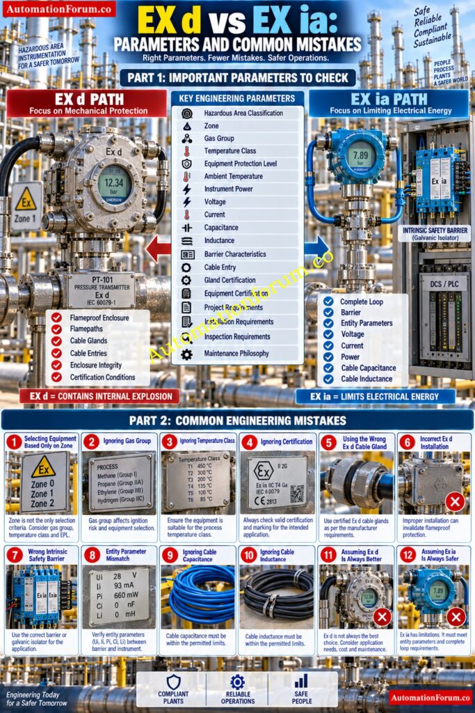
Before approving hazardous area instrumentation, check:
- Hazardous area classification
- Zone
- Gas group
- Temperature class
- Equipment protection level
- Ambient temperature
- Instrument power requirement
- Signal type
- Available voltage
- Maximum current
- Internal capacitance
- Internal inductance
- Cable capacitance
- Cable inductance
- Barrier or isolator characteristics
- Associated apparatus
- Enclosure requirements
- Cable entry requirements
- Gland certification
- Equipment certification marking
- IECEx or ATEX requirements where applicable
- Project specifications
- Installation requirements
- Inspection requirements
- Maintenance philosophy
For Ex d, pay particular attention to the certified enclosure, flame paths, cable entries and conditions of use.
For Ex ia, pay particular attention to the complete loop, associated apparatus, entity parameters and cable characteristics.
Identify Hazardous Zones Correctly Before Selecting Equipment: Hazardous area classification
Common Mistakes When Selecting Ex d and Ex ia Equipment
A common mistake is selecting equipment based only on the zone. The zone is important, but gas group, temperature class, EPL and certificate conditions also matter.
Another mistake is ignoring the cable gland. An incorrectly selected gland can compromise an Ex d installation even when the instrument itself has the correct certification.
For Ex ia systems, incorrect barrier selection is a frequent engineering problem. The barrier and field device must have compatible parameters.
Engineers can also overlook cable capacitance and inductance. These values can affect whether the complete intrinsic safety loop remains within its permitted limits.
Another mistake is assuming that Ex d is always more robust or that Ex ia is always safer. These assumptions ignore the actual protection philosophy and application.
Equipment should also never be operated outside the conditions stated in its certification.
Generate Reliable SIL Evidence Before Safety Approval: SIL Verification Report (Safety Integrity Level Verification Report)
Troubleshooting Ex d and Ex ia Systems
For Ex d equipment, inspect the enclosure condition, covers, flame paths, cable glands, unused entries, corrosion and mechanical damage according to the applicable inspection requirements.
Do not modify a flameproof enclosure simply to solve a wiring or mounting problem. Any modification must remain within the certified arrangement and applicable requirements.
For Ex ia systems, check barrier wiring, loop voltage, entity parameters, cable capacitance, cable inductance, isolator selection and applicable grounding arrangements.
If a transmitter shows unstable readings, do not immediately assume the transmitter is defective. Check the complete loop and verify whether the associated apparatus and field wiring are suitable.
Hazardous area troubleshooting must follow the plant safety procedure, equipment certificate requirements and applicable inspection practices.
Best Practices for Choosing Ex d or Ex ia
Start with the hazardous area classification drawing rather than personal preference.
Then review the instrument data sheet, project specification, certification, hazardous area philosophy and installation requirements.
For Ex ia, document the complete intrinsic safety loop and verify the relevant parameters.
For Ex d, verify the certified enclosure arrangement, cable entries and installation conditions.
Also consider commissioning, inspection, maintenance and future replacement. A protection concept that is technically suitable but difficult to maintain within the plant philosophy may not be the best engineering choice.
Discover Why NAMUR Sensors Excel In Hazardous Applications: Why NAMUR Sensors are Essential in Explosive and Hazardous Areas ?
Which Is Better: Ex d or Ex ia?
There is no universal winner in the EX d vs EX ia comparison.
Ex ia can be highly suitable for low energy measurement and control circuits where intrinsic safety parameters can be verified and maintained.
Ex d can be appropriate for equipment requiring a flameproof enclosure and for applications where the electrical power or equipment construction does not fit conveniently within an intrinsic safety arrangement.
The final decision should be based on hazardous area classification, certified equipment, equipment protection level, gas group, temperature class, electrical characteristics, installation requirements, project standards and maintenance philosophy.
Choose The Right Isolation Method For Reliable IS Signals: Understanding Zener vs Galvanic Isolation in IS Loops for 4 to 20 mA Systems
Frequently Asked Questions about EX d vs EX ia: Choose the Right Protection
What is the difference between flameproof and intrinsically safe equipment?
Flameproof equipment contains an internal explosion within a certified enclosure and prevents flame from reaching the surrounding atmosphere.
Intrinsically safe equipment restricts electrical and thermal energy to avoid ignition under defined situations.
What is the difference between Ex d and Ex i?
Ex d contains an internal explosion in a certified flameproof container, preventing the propagation of flame.
Ex i limits electrical and thermal energy in the hazardous area circuit and hence interrupts ignition.
What is the difference between ATEX and intrinsically safe?
ATEX is a European regulatory framework for equipment and protective systems intended for potentially explosive atmospheres.
Intrinsic safety is an explosion protection concept that limits electrical and thermal energy to prevent ignition.
What is Class I Division 2 intrinsically safe?
Class I Division 2 identifies an area where flammable gases or vapors are not normally present but may occur under abnormal conditions.
Intrinsically safe equipment can be used when its certification and installation requirements permit the application.
What are Class I, II, and III hazardous locations?
Class I sites are places in which flammable gasses or vapors are present; Class II locations are locations in which combustible dust is present; and Class III locations are locations in which ignitable fibers or flyings are present.
These classifications are used to evaluate what equipment and protection is appropriate for hazardous locations.
What is Class I Division 2 Group D?
Class I Division 2 Group D applies to locations where certain flammable gases or vapors may occur under abnormal conditions.
Group D covers gases and vapors such as gasoline, propane and similar substances under the applicable classification system.
What is Class I Zone 2 hazardous area?
Class I Zone 2 describes an area where an explosive gas atmosphere is not likely during normal operation but may occur briefly.
Equipment installed there must have suitable protection and certification for the specific hazardous location.
What are Class II hazardous materials?
Class II hazardous areas are those in which combustible dust is present, or may be present, in the air in sufficient quantity to produce an explosion or fire danger.
Examples include certain dusts from grain, plastics, chemicals, metals and other combustible materials.
What is Class I hazardous area?
A Class I hazardous area is a location where flammable gases or vapors may be present in quantities capable of creating a fire or explosion hazard.
Equipment selection must consider the applicable division or zone, group, temperature requirements and certification.
What is the main difference between Ex d and Ex ia?
Ex d contains an internal explosion within a certified enclosure and prevents flame propagation into the surrounding atmosphere.
Ex ia limits electrical and thermal energy so the circuit does not become an ignition source under specified conditions.
Is Ex ia safer than Ex d?
Neither protection concept is universally safer because they control ignition risk using different engineering principles.
The correct choice depends on the hazardous area, equipment certification, circuit design and project requirements.
Can Ex ia equipment be used in Zone 0?
Ex ia equipment can be suitable for Zone 0 when its certification and marking specifically permit Zone 0 installation.
The complete circuit and associated apparatus must also satisfy the applicable intrinsic safety requirements.
Understand Explosion Protection Before Entering Hazardous Plant Areas: Exploring Explosion-Proof: Safety in Hazardous Environment
Can Ex d equipment be used in Zone 1?
Ex d equipment can be suitable for Zone 1 when its certified marking and equipment protection level match the application.
The enclosure, cable entries and installation must also comply with the certified arrangement.
When should Ex d be selected?
Ex d can be selected when equipment is designed for flameproof enclosure protection and its certification matches the hazardous area.
It can also be practical for equipment requiring higher power where intrinsic safety is not suitable.
When should Ex ia be selected?
Ex ia is particularly useful for low energy instrumentation and measurement circuits where the complete loop satisfies intrinsic safety requirements.
The field device, associated apparatus and cable parameters must be compatible.
What parameters should be checked before selecting Ex ia?
Check voltage, current, power, capacitance and inductance for the field device, associated apparatus and interconnecting cable.
Also verify the hazardous area, gas group, temperature class, equipment protection level and certification.
Can Ex d and Ex ia be used in the same process plant?
Yes, a process plant can use both protection concepts for different instruments and equipment.
Each device and installation must independently satisfy its applicable certification and project requirements.
EX d vs EX ia: Choosing the Right Hazardous Area Protection
The main EX d vs EX ia difference is the way each protection concept controls ignition risk. Ex d uses a certified flameproof enclosure to contain an internal explosion, while Ex ia limits electrical and thermal energy to prevent ignition.
For practical instrument selection, engineers should begin with hazardous area classification and then verify zone, gas group, temperature class, equipment protection level, electrical requirements, certification, installation conditions and maintenance philosophy.
Ex d and Ex ia should never be treated as interchangeable labels. The correct choice is the one that matches the certified equipment, complete installation and project requirements.
Refer the below link for the What is HAZOP Study in Instrumentation Engineering for EPC Engineers in Process Industries
