- Introduction to Pressure Transmitter 22 mA Fault Signals
- Understanding the 22 mA Signal in Pressure Transmitters
- Understanding NAMUR NE43 Fault Signaling
- Can a Pressure Transmitter Output More Than 20 mA?
- Top Causes of a Pressure Transmitter Showing 22 mA
- How to Troubleshoot a Pressure Transmitter Showing 22 mA
- Step 1: Verify the DCS Reading
- Step 2: Measure Actual Loop Current
- Step 3: Check the Transmitter Local Display
- Step 4: Review HART Diagnostic Messages
- Step 5: Verify Actual Process Pressure
- Step 6: Inspect Impulse Lines and Manifolds
- Step 7: Perform Calibration Verification
- Step 8: Simulate Loop Output Signals
- Real Industrial Case Studies of 22 mA Fault Conditions
- How DCS Engineers Should Investigate a 22 mA Signal
- How Maintenance Engineers Should Investigate a 22 mA Signal
- Common Mistakes When Troubleshooting a 22 mA Signal
- Best Practices to Prevent Pressure Transmitter 22 mA Faults
- Frequently Asked Questions About Pressure Transmitter 22 mA Signals
- What Does 22 mA Mean on a Pressure Transmitter?
- Is 22 mA Always a Fault Condition?
- Can Overpressure Cause a 22 mA Signal?
- What Is NAMUR NE43 Fail High?
- How Do I Check if a Pressure Transmitter Is Faulty?
- Can Wiring Problems Cause 22 mA?
- Why Does My DCS Show 22 mA but My Meter Shows 20 mA?
- How Do Smart Transmitters Report Internal Failures?
- Why Is the Transmitter Output 4–20 mA?
- How to Check mA on a Pressure Transmitter?
- What Is a 4–20 mA Transducer?
- How to Read a 4–20 mA Signal?
- How to Calibrate 4–20 mA?
- What Is Span in 4–20 mA?
- What Is Live Zero in a 4–20 mA Signal?
- What Is the Difference Between Over-Range and Fail-High?
- Can a Pressure Transmitter Output More Than 20 mA Normally?
- What Tools Are Used to Troubleshoot a 22 mA Signal?
- Conclusion: Key Takeaways for Instrument Engineers
Introduction to Pressure Transmitter 22 mA Fault Signals
Why Is My Pressure Transmitter Showing 22 mA?
A pressure transmitter that normally operates between 4 mA and 20 mA suddenly starts showing 22 mA on the DCS. The control room receives a high alarm while field conditions appear normal. Is the transmitter faulty? Is the process actually over pressure? Or is the transmitter intentionally signaling a diagnostic condition?
Why a 22 mA Signal Should Never Be Ignored
This situation occurs daily in refineries, chemical plants, power stations, oil and gas facilities, pharmaceutical plants, and water treatment systems. A technician sees 22 mA on the DCS trend, operations report a high pressure alarm, and maintenance is immediately asked to replace the transmitter. In many cases, replacing the transmitter does not solve the problem because the 22 mA signal was actually communicating a diagnostic condition rather than a process measurement.
How Smart Pressure Transmitters Communicate Diagnostic Faults
Modern smart pressure transmitters are far more intelligent than older analog devices. They continuously monitor sensor health, electronics integrity, memory status, and internal diagnostics. When a serious problem is detected, the transmitter intentionally drives the output above the normal measurement range to alert the control system that something is wrong.
What Engineers Will Learn in This Troubleshooting Guide
Understanding the 22 mA Signal in Pressure Transmitters
What Does 22 mA Mean in a 4–20 mA Loop?
In a standard analog loop:
- 4 mA represents the Lower Range Value
- 20 mA represents the Upper Range Value
For example, if a transmitter is calibrated from 0 bar to 100 bar:
| Pressure | Output Current |
| 0 bar | 4 mA |
| 25 bar | 8 mA |
| 50 bar | 12 mA |
| 75 bar | 16 mA |
| 100 bar | 20 mA |
Why Smart Transmitters Generate Signals Above 20 mA
Many engineers assume the transmitter should never exceed 20 mA. However, smart transmitters are intentionally designed to generate currents above the measuring range when abnormal conditions occur.
Understanding Live Zero Concept in Instrumentation
This allows the transmitter to distinguish between:
- A genuine process value
- A diagnostic condition
- A hardware failure
- A sensor problem
The concept behind this design is called Live Zero.
Why Engineers Should Never Ignore a 22 mA Output
At 4 mA the transmitter is still powered and operational. If the signal drops to 0 mA, engineers immediately know that a wire break, power failure, or major loop problem exists.
Similarly, when the current rises above 21 mA, the transmitter is often indicating that it has detected a fault condition.
Avoid Costly Calibration Errors With This Proven Method: How to simulate 4-20ma signal with Loop Calibrator ?
Understanding NAMUR NE43 Fault Signaling

What Is NAMUR NE43?
Before standardized diagnostics existed, every transmitter manufacturer used different current values to indicate failures. This created confusion for operators and control system engineers.
To solve this problem, the industry adopted NAMUR NE43.
Refer the below link for the How to do troubleshooting of a 4-20mA loop?
NAMUR NE43 Current Signal Ranges
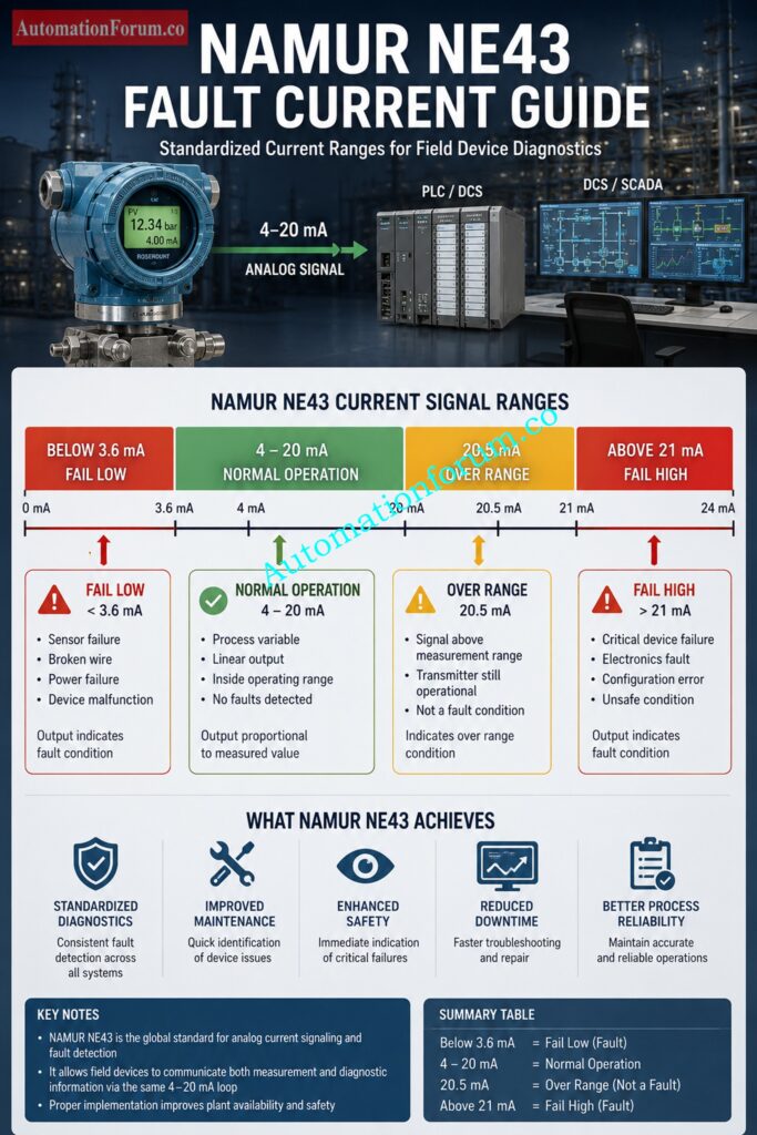
NAMUR NE43 defines specific current levels that represent abnormal conditions.
| Current Value | Meaning |
| Below 3.6 mA | Fail Low |
| 4 to 20 mA | Normal Measurement |
| Up to 20.5 mA | Over Range |
| Above 21 mA | Fail High Diagnostic |
Discover Why Industry Never Abandoned Live Zero: Why not use 0-20mA & 0-15psi instead of 4-20mA & 3-15psi?
Why Most Modern Pressure Transmitters Follow NAMUR NE43
When a pressure transmitter enters a fail high condition, it intentionally drives the output to approximately 21 mA to 22 mA.
This is not a measurement.
It is a message.
The transmitter is effectively telling the control system:
“I have detected a problem and my process value can no longer be trusted.”
Many modern DCS, PLC, and SIS systems are configured to recognize these fault currents and generate instrument failure alarms.
Simplify Complex Flow Signals Using Proven Techniques: Square Root Extraction Signal to Linear Signal Converter: 4-20mA, 3-15 Psi, 1-5 Volt Signals
Can a Pressure Transmitter Output More Than 20 mA?
Yes. Modern smart pressure transmitters can output more than 20 mA during over-range conditions, diagnostic alarms, or internal device faults. These signals help distinguish normal process measurements from abnormal operating conditions.
Normal Operating Range of a Pressure Transmitter
A standard pressure transmitter operates between 4 mA and 20 mA, where 4 mA represents the Lower Range Value (LRV) and 20 mA represents the Upper Range Value (URV).
Over-Range Conditions
If the process pressure exceeds the calibrated range, the transmitter may output slightly above 20 mA to indicate an over-range measurement while remaining operational.
Sensor Diagnostic Conditions
When the sensor detects a problem such as degradation, saturation, or measurement failure, the transmitter may generate a diagnostic current above 21 mA.
Internal Device Failure Conditions
Electronics faults, memory errors, or processor failures can cause the transmitter to enter a fail-high mode and output approximately 21–22 mA.
Manufacturer-Specific Fault Signaling Methods
The fault current values varies from one manufacturer to another, for example 21 mA, 21.6 mA or 22 mA. Check the device documentation and setup settings to always read the signal appropriately.
Critical Safety Barrier Selection Mistakes Engineers Make: Understanding Zener vs Galvanic Isolation in IS Loops for 4 to 20 mA Systems
Top Causes of a Pressure Transmitter Showing 22 mA
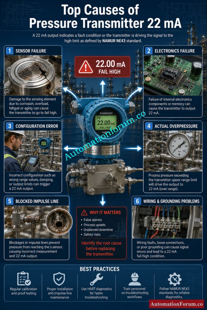
Internal Pressure Sensor Failure
The most typical cause of a 22 mA output is a sensor failure.
Inside every pressure transmitter is a sensing element that converts pressure into an electrical signal. Over time, this sensing element can degrade because of:
- Pressure cycling
- Process vibration
- Corrosion
- Temperature stress
- Mechanical shock
When the sensor output becomes invalid, the transmitter diagnostics recognize the problem and activate the fail high current.
A key indicator of sensor failure is that the transmitter continues showing 22 mA regardless of actual process pressure.
Transmitter Electronics Failure
Modern pressure transmitters contain microprocessors, memory modules, analog circuits, and digital communication systems.
Failures can occur due to:
- Component aging
- Power surges
- Moisture ingress
- Lightning events
- Excessive temperature
A damaged electronics module may still power up while producing a fault current output.
In many plants, technicians replace the entire transmitter only to discover that a replaceable electronics board was the actual problem.
Incorrect Transmitter Configuration
Configuration mistakes are surprisingly common.
During commissioning or maintenance activities, engineers may accidentally change:
- Measurement range
- Fail mode selection
- Engineering units
- Damping settings
- Output limits
A transmitter configured for fail high mode will intentionally generate approximately 22 mA whenever an internal diagnostic alarm occurs.
Always verify configuration before replacing hardware.
Calculate HART Loop Limits Before Communication Fails: Advanced HART Loop Calculator for Reliable 4 to 20 mA and HART Communication
Actual Process Overpressure Condition
Not every 22 mA condition originates from the instrument.
Sometimes the process is genuinely exceeding the calibrated range.
Examples include:
- Pump dead heading
- Compressor discharge blockage
- Control valve failure
- Closed downstream isolation valve
- Relief valve malfunction
Before declaring the transmitter faulty, engineers should verify actual pressure using a calibrated gauge or portable calibrator.
Many unnecessary transmitter replacements occur because actual process conditions were never checked.
Blocked Impulse Lines
Impulse line problems create some of the most confusing troubleshooting situations in process plants.
A blocked impulse line can trap pressure inside the sensing system.
This trapped pressure may remain even after actual process pressure has changed.
Common causes include:
- Wax buildup
- Sludge accumulation
- Ice formation
- Condensate blockage
- Process contamination
The transmitter may show a constant high pressure state when the process is working normally.
Wiring Faults and Grounding Issues
Field wiring problems can produce abnormal transmitter behavior.
Common issues include:
- Short circuits
- Ground faults
- Water ingress
- Damaged cable insulation
- Loose terminals
- Incorrect terminations
Wiring issues do not necessarily cause 22 mA directly, but they can produce unstable operating circumstances that cause the transmitter diagnostics to trip.
Every troubleshooting effort should include a complete wiring inspection.
DCS Analog Input Card Configuration Errors
Sometimes the transmitter is healthy while the DCS is wrong.
Problems may include:
- Incorrect AI card scaling
- Engineering unit mismatch
- Wrong channel configuration
- Saturated input card
- Software mapping errors
A field meter showing 20 mA while the DCS displays 22 mA immediately points toward a control system issue.
This simple verification can save hours of troubleshooting.
The Analog Signal Problem Most Engineers Overlook: Beyond Zero: Understanding the Dead Zero Problem in Industrial Analog Signals
How to Troubleshoot a Pressure Transmitter Showing 22 mA
When a pressure transmitter shows 22 mA, experienced instrument engineers avoid making assumptions. Replacing the transmitter right away can waste useful maintenance time and may not fix the real problem. A systematic troubleshooting procedure can help to find out whether the fault is in the process, the transmitter, the wiring, the power supply or the control system.
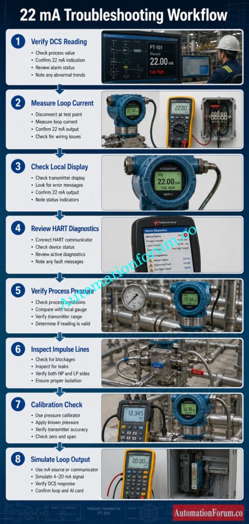
Step 1: Verify the DCS Reading
The first step is to look at what the control system is telling you. Operators will often tell you that the transmitter is reading 22 mA, but the engineer must figure out if that is the actual analog signal, a scaled engineering number, or diagnostic status coming from the DCS.
Review the following:
- Current value displayed by the DCS
- Process value in engineering units
- Active alarms and events
- Diagnostic messages
- Historical trend data
- Bad PV or instrument fault indicators
Make sure to look at the history of the trend. Check whether the signal rose slowly to 22 mA or surged rapidly from a normal value to a fault situation. A quick jump is usually a diagnostic event, a gradual increase may signal a real process disturbance.
The purpose of this step is to determine if the DCS is reporting a true high pressure condition or an instrument problem.
Typical Observations
| Observation | Possible Conclusion |
| Sudden jump to 22 mA | Transmitter diagnostic fault |
| Gradual increase to 22 mA | Process pressure increase |
| Bad PV status active | Instrument fault likely |
| High pressure alarm only | Process condition possible |
The Analog Signal Problem Most Engineers Overlook: Beyond Zero: Understanding the Dead Zero Problem in Industrial Analog Signals
Step 2: Measure Actual Loop Current

One of the most typical troubleshooting blunders is to trust the DCS display alone. The control system can only show what it understands from the input.
Before going any further , physically measure the loop current using a calibrated milliamp meter .
Measure the current directly at:
- Transmitter terminals
- Junction box
- Marshalling cabinet
- DCS input terminals
Compare the measured value to the DCS indication.
If the current reads 22 mA it is probably the transmitter or field loop that is the problem.
If the measured current is significantly different from the DCS measurement, check:
- Analog input card configuration
- Scaling errors
- Wiring faults
- Input channel problems
This simple test rapidly distinguishes field instrument difficulties from control system problems.
Typical Findings
| Measured Current | DCS Reading | Engineering Conclusion |
| 22 mA | 22 mA | Field device issue |
| 20 mA | 22 mA | DCS scaling issue |
| 4 mA | 22 mA | Input card problem |
| Fluctuating | Stable | Wiring or grounding issue |
Verify Loop Integrity Faster With This Field Method: Live Signal Verification 4 to 20 mA Loop Standard Operating Procedure (SOP)
Step 3: Check the Transmitter Local Display
Modern smart pressure transmitters have powerful self diagnostic capability. The local display often provides valuable information long before a maintenance technician connects a communicator.
Visit the transmitter in the field and observe:
- Process value
- Status indicators
- Diagnostic messages
- Fault codes
- Sensor health indicators
Look for messages such as:
- Sensor Failure
- Electronics Fault
- Device Error
- Maintenance Required
- Configuration Error
- Output Saturation
- Over Range Warning
A transmitter displaying a clear sensor failure message can save hours of unnecessary troubleshooting.
Also compare the local display pressure value with the DCS value. Large disparities can be indicative of communication, scaling or setup problems.
In many cases the transmitter already knows exactly what the problem is and is trying to tell you about it.
Solve Persistent 4-20mA Issues Like An Expert: 4-20 mA Loop Troubleshooting with Loop Calibrators : A Practical Guide
Step 4: Review HART Diagnostic Messages
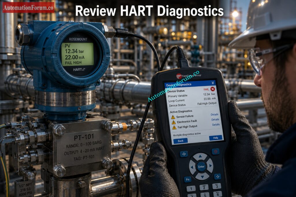
If the local display does not have adequate information, connect a HART communicator and open the transmitter diagnostics.
Today smart transmitters regularly check hundreds of internal parameters and keep crucial failure data.
Review:
- Device status
- Sensor diagnostics
- Electronics diagnostics
- Output diagnostics
- Configuration settings
- Event history
- Maintenance alerts
- Fault logs
Keep a close watch on active alerts and events that have been logged recently.
For example:
- Sensor Saturation might indicate overpressure.
- Electronics Failure might be a damaged circuit.
- Configuration Changed can be human error.
- Maintenance activities can be forced.
Many faults can be diagnosed without removing the transmitter from service.
The event log often indicates the precise time the issue began . This allows engineers to match the fault with events in the process or maintenance actions.
Step 5: Verify Actual Process Pressure
Never presume the transmitter is incorrect.
Verify actual process pressure independently before changing any equipment.
Connect a certified pressure gauge, pressure calibrator, or reference standard to the process connection.
Compare:
- Actual measured pressure
- Local transmitter indication
- DCS displayed value
This comparison is critical because genuine process overpressure conditions can also drive the transmitter into an over range or fault state.
For example:
A transmitter calibrated from 0 to 10 bar may experience an actual process pressure of 14 bar due to a blocked discharge line. In this case, the transmitter may be functioning correctly while the process is operating abnormally.
Always verify process conditions before declaring an instrument faulty.
Key Questions
- Is the process actually over pressure?
- Are operators reporting abnormal conditions?
- Have recent process changes occurred?
- Are control valves operating correctly?
Stop Confusing These Two Critical Signal Concepts: Understanding the Difference Between Live Zero and Dead Zero in 4 to 20 mA Signals
Step 6: Inspect Impulse Lines and Manifolds
One of the most common sources of pressure measurement errors that are often neglected is the impulse line.
If pressure isn’t getting through to the detecting element properly even a healthy transmitter will not produce accurate data.
Inspect for:
- Blockages
- Leaks
- Closed root valves
- Partially closed isolation valves
- Condensate buildup
- Frozen impulse lines
- Air pockets
- Damaged tubing
In steam applications condensate may accumulate and trap pressure and provide incorrect readings.
In hydrocarbon service, wax or sludge buildup may partially block the line.
In cold climates, frozen impulse lines can completely isolate the transmitter from the process.
Impulse line problems frequently create false high pressure indications that appear identical to transmitter failures.
Step 7: Perform Calibration Verification
If no obvious fault has been identified, perform an as found calibration test.
Calibration testing will assist identify if the transmitter is accurately converting pressure to a current output.
Use known pressure values over the operational range and compare the actual output values to the expected ones.
Observe:
- Zero shift
- Span shift
- Linearity errors
- Repeatability problems
- Hysteresis effects
For example:
A transmitter calibrated for 0 to 100 bar should produce:
- 4 mA at 0 bar
- 12 mA at 50 bar
- 20 mA at 100 bar
Significant deviations may indicate:
- Sensor degradation
- Electronics problems
- Mechanical damage
- Aging components
Diagnostics typically don’t show problems that calibration findings do.
Step 8: Simulate Loop Output Signals
The last stage is to check the entire signal line from transmitter to control system.
Use the transmitter’s loop test function or a process calibrator to force a known current output.
Simulate:
- 4 mA
- 12 mA
- 20 mA
Watch the DCS reaction to each value.
Expected results shall be within the chosen engineering range.
For example:
| Simulated Current | Expected DCS Response |
| 4 mA | Lower Range Value |
| 12 mA | Mid Range Value |
| 20 mA | Upper Range Value |
If the DCS displays incorrect values during simulation, the problem likely exists in:
- Analog input configuration
- Signal scaling
- Database configuration
- Control system programming
This test is extremely effective because it verifies the transmitter, wiring, marshalling, analog input card, and DCS configuration as a complete loop.
By the completion of Step 8, engineers can typically determine whether the root cause is a transmitter fault, process issue, wiring problem, impulse line problem, calibration issue, or control system configuration error. This methodical technique takes the guessing out of troubleshooting and dramatically decreases field troubleshooting time.
Essential Intrinsic Safety Knowledge Every Engineer Needs: Intrinsic Safety Protection Systems: Understanding Ex ia, Ex ib, and Ex ic
Real Industrial Case Studies of 22 mA Fault Conditions
Refinery Pressure Sensor Failure Case Study
During regular operation, a refinery reactor pressure transmitter suddenly indicated 22 mA.
Normal process pressure was established using a mechanical gauge.
HART diagnostics indicated sensor failure.
The sensing module was replaced and normal operation resumed.
The transmitter was accurately warning operators that its measurement could no longer be trusted.
Commissioning Configuration Error Case Study
During startup, a newly installed transmitter repeatedly generated 22 mA alarms.
Engineers initially suspected a defective device.
Further investigation showed that fail high diagnostics had been enabled during factory configuration.
The transmitter was operating exactly as designed.
Correct configuration resolved the issue.
Achieve Accurate HART Calibration With Confidence: HART transmitter calibration procedure – For pressure transmitter
Compressor False Shutdown Case Study
A compressor shutdown occurred because the control system interpreted a diagnostic current as an extreme pressure condition.
The transmitter was actually reporting an internal fault.
The shutdown logic had not been properly configured to distinguish between a process alarm and an instrument alarm.
This incident underscored the need for a proper alarm concept.
Calibration Steps That Prevent Expensive Measurement Errors: Step-by-Step Procedure to Calibrate an Absolute Pressure Transmitter
How DCS Engineers Should Investigate a 22 mA Signal
For a 22 mA signal, DCS engineers should check the following:
- AI card configuration
- NAMUR alarm thresholds
- Engineering unit scaling
- Alarm settings
- Historical trends
- Control strategy logic
- Bad PV handling
- Signal validation functions
In particular, data from historians are essential since they frequently tell exactly when the fault began and what process circumstances were present at that moment.
Often trend analysis will find the root reason quicker than troubleshooting in the field.
Build Reliable Calibration Setups Without Wiring Mistakes: Wiring Diagram for Pressure Transmitter Calibration in Workbench using HART
How Maintenance Engineers Should Investigate a 22 mA Signal
Maintenance professionals should concentrate on:
- Sensor health
- Wiring integrity
- Junction boxes
- Moisture ingress
- Loop voltage
- Grounding
- Calibration records
- Impulse lines
- Valve positions
- HART diagnostics
A systematic inspection method prevents unnecessary component replacement.
Decode Complex Instrument Drawings Faster Than Ever: How to Read Pressure Transmitter Hookup Drawings ?
Common Mistakes When Troubleshooting a 22 mA Signal
Some of the errors engineers make are:
- Replacing the transmitter immediately
- Ignoring HART diagnostics
- Failing to measure actual current
- Assuming process overpressure
- Ignoring impulse line conditions
- Skipping calibration checks
- Overlooking wiring faults
- Ignoring grounding problems
- Missing configuration errors
- Trusting only the DCS display
Such errors raise downtime and maintenance expenses.
Prevent Startup Delays Using This Proven Checklist: Pressure Transmitter Commissioning Checklist
Best Practices to Prevent Pressure Transmitter 22 mA Faults
Successful factories have less incidents to troubleshoot through:
- Routine calibration verification
- Periodic loop checks
- Scheduled diagnostic reviews
- Configuration management procedures
- Proper grounding practices
- Instrument health monitoring
- Regular impulse line inspection
- Spare transmitter management
- Maintenance record analysis
- Asset management systems
In a predictive maintenance scheme, transmitter degradation is typically detected well before it reaches a fail high status.
Ensure Accurate Flow Measurement Before Plant Startup: Differential Pressure Transmitter Commissioning Checklist for Flow Measurement Applications
Frequently Asked Questions About Pressure Transmitter 22 mA Signals
What Does 22 mA Mean on a Pressure Transmitter?
A 22 mA output is a transmitter diagnostic fault or fail-high situation, not a typical process measurement. It is often used to tell the control system that the gadget has identified an internal problem.
Is 22 mA Always a Fault Condition?
Sometimes not. A signal of 22 mA may indicate a transmitter failure, but can also be seen under over-range conditions or in some manufacturer specified diagnostic modes.
Can Overpressure Cause a 22 mA Signal?
Yes. If the process pressure is greater than the transmitter calibrated range, the device may drive the output above 20 mA or go into a fault state depending on the design.
What Is NAMUR NE43 Fail High?
NAMUR NE43 is an industry standard that defines fault signaling in 4–20 mA loops. A fail-high condition is typically represented by a current above 21 mA to indicate a device fault.
How Do I Check if a Pressure Transmitter Is Faulty?
Check the loop current, check the real process pressure, and check HART diagnostics or local display fault warnings. Compare field measurements with DCS results to find anomalies.
Can Wiring Problems Cause 22 mA?
Yes. Transmitter diagnostic warnings and anomalous current outputs can be caused by unstable situations, such as short circuits, grounding problems, moisture intrusion or damaged connections.
Why Does My DCS Show 22 mA but My Meter Shows 20 mA?
This is usually a DCS analog input scaling error, configuration fault or input card problem., or input card issue. The field measurement should always be verified before replacing the transmitter.
Avoid Installation Mistakes That Damage Transmitters Early: Step by Step Pressure Transmitter Installation Procedure
How Do Smart Transmitters Report Internal Failures?
Smart transmitters use diagnostic currents, HART alerts, status flags, and fault codes to communicate sensor, electronics, memory, or configuration problems to maintenance personnel.
Why Is the Transmitter Output 4–20 mA?
The 4–20 mA standard provides reliable signal transmission over long distances while allowing the transmitter to remain powered through the same loop. It is widely used because it is resistant to electrical noise and wiring losses.
How to Check mA on a Pressure Transmitter?
Connect a calibrated milliamp meter in series with the loop and measure the actual current output. Readings should correspond to the pressure value according to the transmitter calibration range.
Improve Measurement Reliability Through Better Range Selection: Rangeability vs. Turndown Ratio and their Implications for Pressure Transmitter Selection
What Is a 4–20 mA Transducer?
A 4–20 mA transducer converts a physical process variable such as pressure, temperature, or level into a proportional current signal. The signal can then be transmitted to a PLC, DCS, or control system.
How to Read a 4–20 mA Signal?
Convert the measured current into the corresponding engineering value using the transmitter’s calibrated range. For example, 12 mA represents 50% of the configured measurement span.
How to Calibrate 4–20 mA?
Apply known input values using a reference standard and verify that the output is 4 mA at the lower range and 20 mA at the upper range. Adjust zero and span settings if necessary.
What Is Span in 4–20 mA?
Span is the difference between the Upper Range Value (URV) and Lower Range Value (LRV) of a transmitter. It defines the measurement range represented by the 4–20 mA signal.
What Is Live Zero in a 4–20 mA Signal?
Live Zero means the transmitter outputs 4 mA instead of 0 mA at the lower range value. This allows engineers to distinguish a valid zero measurement from a power loss or broken wire condition.
What Is the Difference Between Over-Range and Fail-High?
An over-range signal indicates the process value has exceeded the calibrated range, while a fail-high signal indicates a transmitter diagnostic fault. Both may produce currents above 20 mA but have different causes.
Can a Pressure Transmitter Output More Than 20 mA Normally?
Yes. Many smart transmitters can output slightly above 20 mA during over-range conditions and up to approximately 22 mA during diagnostic fault conditions.
Loop Checking Techniques That Catch Faults Early: Method Statement for Loop Checking of Pressure Transmitter Loop
What Tools Are Used to Troubleshoot a 22 mA Signal?
Common tools include a milliamp meter, HART communicator, pressure calibrator, digital multimeter, and certified reference pressure gauge. These help verify the transmitter, loop, and process conditions.
Conclusion: Key Takeaways for Instrument Engineers
When to Replace the Pressure Transmitter
A pressure transmitter showing 22 mA should never be ignored or automatically assumed to be a bad transmitter. In modern process plants, a 22 mA signal is often a deliberate diagnostic message indicating that the device has detected a condition that may compromise measurement accuracy.
The root cause may be sensor failure, electronics damage, configuration errors, wiring issues, impulse line problems, actual process overpressure, or control system configuration mistakes.
Improving Reliability Through Proper Diagnostics
The most effective troubleshooting approach is systematic. Verify the DCS reading, measure the actual loop current, review HART diagnostics, confirm process conditions, inspect impulse lines, validate calibration, and evaluate control system configuration.
Experienced instrument engineers understand that a 22 mA signal is not just a number. It is valuable diagnostic information from the transmitter. Proper interpretation can prevent unnecessary shutdowns, avoid incorrect maintenance actions, improve reliability, and ensure safe plant operation.
When a transmitter outputs 22 mA, the device is asking engineers to investigate. The sooner the root cause is identified, the safer and more reliable the process will remain.
Refer the below link for the Factors that Influence the Accuracy of your Pressure Transmitter