
- What is Shutdown Philosophy and Why is it Important?
- What Is a Shutdown Philosophy in Process Safety?
- Why Is Shutdown Philosophy Important in Engineering Projects?
- What Is the Shutdown Level Hierarchy?
- How Is a Shutdown Philosophy Developed?
- What Should a Shutdown Philosophy Document Include?
- Shutdown Philosophy and Cause and Effect Matrix
- Shutdown Philosophy and SIS Engineering
- Shutdown Philosophy Engineering Documentation
- Shutdown Philosophy Engineering Workflow
- ESD Shutdown Reset and Restart Philosophy
- Practical Shutdown Philosophy Example
- Common Shutdown Philosophy Engineering Mistakes
- Why Instrumentation and Control Engineers Must Understand Shutdown Philosophy
- Shutdown Philosophy Frequently Asked Questions
- Shutdown Philosophy: From Process Safety to ESD and SIS Implementation
What is Shutdown Philosophy and Why is it Important?
This is where the Shutdown Philosophy becomes important.
A Shutdown Philosophy defines which events require a shutdown, what level of shutdown is appropriate, which equipment must stop, which process sections must be isolated, when depressurization is required and which utilities should remain available. It also establishes how shutdowns are initiated, reset and followed by a controlled restart.
The response should match the severity of the event. A local compressor problem should not automatically shut down an entire facility. On the other hand, a major fire or hazardous release may require process isolation, equipment shutdown and depressurization.
A well prepared Shutdown Philosophy gives engineers a common basis for developing the detailed safety and control system documentation.
What Is a Shutdown Philosophy in Process Safety?
Shutdown Philosophy Definition
A Shutdown Philosophy is a key process safety and engineering document that establishes the overall strategy for bringing equipment, process units, process trains or an entire facility to a defined safe condition.
Purpose of a Shutdown Philosophy Document
It provides the engineering intent behind the Emergency Shutdown System and, where applicable, the Safety Instrumented System.
The philosophy is not the same as the Cause and Effect Matrix. The Shutdown Philosophy establishes the overall shutdown strategy.
Master Voting Architectures Before Designing Your Safety System: Voting Logic in Safety Instrumented System
Shutdown Philosophy vs Cause and Effect Matrix
The Cause and Effect Matrix then converts that strategy into specific initiating causes and resulting actions. Shutdown logic diagrams and SIS application logic implement those actions in the control system.
For example, the philosophy may establish that a serious hazardous event requires process isolation and depressurization. Detailed engineering must then determine the initiating signals, shutdown valves, blowdown valves, logic requirements, feedback signals and associated permissives.
Stop Confusing Shutdown Levels Before Your Next ESD Design: ESD vs PSD: Difference Between Emergency Shutdown System and Process Shutdown System
Why Is Shutdown Philosophy Important in Engineering Projects?
Role of Shutdown Philosophy in Process Safety
A process facility involves several engineering disciplines, and each discipline needs to understand the intended shutdown response.
Coordination Between Process Instrumentation and Control Engineering
Process engineers define process behaviour and isolation requirements. Process safety engineers assess hazardous scenarios. Instrumentation engineers develop field instrumentation and final element requirements. Control engineers implement the logic. Functional safety engineers address safety instrumented functions where applicable. Electrical, Fire and Gas, operations and commissioning teams also have important interfaces.
Without a clear philosophy, different disciplines can interpret the same event differently. This can result in conflicting Cause and Effect logic, excessive shutdown propagation, incorrect valve actions, unclear isolation boundaries or difficult restart procedures.
Balancing Process Safety and Plant Availability
There is also an important balance between safety and availability. Shutting down too much equipment for every abnormal condition can create unnecessary trips and production losses. Shutting down too little can leave hazardous inventory or process conditions uncontrolled.
The objective is to select the appropriate protective action for the actual hazard.
Refer the below link for the What is Partial Stroke Test (PST)? A Complete Guide for Shutdown and Control Valves
What Is the Shutdown Level Hierarchy?
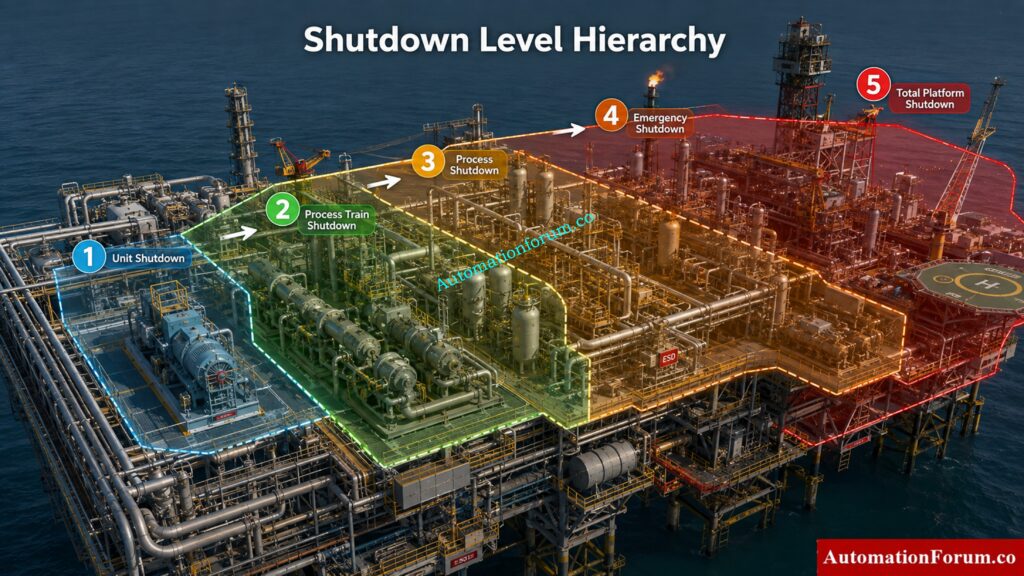
Shutdown terminology and hierarchy vary between facilities, client specifications and project requirements. The following represents a typical hierarchy used in an offshore process environment.
Unit Shutdown
Unit Shutdown is generally the lowest level in this example hierarchy.
It places a specific equipment item or local process unit into a safe condition while allowing unaffected parts of the facility to continue operating.
A compressor package trip, pump shutdown, fired equipment trip or local equipment abnormality may result in this type of action when the hazard does not justify a wider shutdown.
The engineering objective is to contain the problem within the affected area rather than unnecessarily propagating the shutdown to other parts of the facility.
Understand 2oo2 SOV Arrangements Before Selecting Your Configuration: Understanding 2 out of 2 SOV: Working & Configuration
Process Train Shutdown
A Process Train Shutdown affects an entire process train.
This level may be selected when an abnormal condition is significant enough to stop the complete train but does not require shutdown of the whole process facility.
The Shutdown Philosophy should clearly establish train boundaries and interfaces. Engineers need to consider upstream and downstream isolation, common utilities and interactions with other operating trains.
Process Shutdown
Process Shutdown stops the complete process while selected utilities may remain available, depending on the project design.
Keeping appropriate utilities operating can support controlled recovery and make restart easier after the initiating problem has been investigated and corrected.
Whether blowdown is required at this level depends on the process hazard, inventory, equipment arrangement and project requirements. It should never be assumed simply because a shutdown level has a particular name.
Master SIS Fundamentals Before Tackling Advanced SIL Engineering: What is SIS, SIF and SIL? An In-Depth Guide to Functional Safety in Process Industries
Emergency Shutdown
Emergency Shutdown represents a higher consequence response for serious hazardous events.
Possible initiating conditions can include major process deviations, significant hydrocarbon release, critical fire or gas detection or other scenarios identified through project hazard studies.
Depending on the facility, an Emergency Shutdown may involve process shutdown, isolation of hazardous inventory, closure of shutdown valves, stopping rotating equipment, isolation of export systems, depressurization and other emergency actions.
Firewater or deluge actions may also interact with the shutdown strategy where required.
The exact response depends on the location and severity of the event and the results of the applicable safety studies.
Discover How Emergency Block Valves Protect Critical Process Lines: What is an Emergency Block valve and How does it work
Total Platform Shutdown
Total Platform Shutdown represents the highest level in this example hierarchy.
It may be used for extreme emergency scenarios where a much wider facility shutdown is necessary and abandonment may become a consideration.
How Shutdown Levels are Selected
Even at this level, the Shutdown Philosophy needs to identify which essential services must remain available. Emergency power, batteries, communications and other critical systems may have specific requirements depending on the facility design.
Because the consequences of this shutdown level are significant, its initiating conditions and resulting actions must be carefully defined.
Identify Dangerous Signals That Trigger Emergency Valve Actions: Signals for Emergency Valve Shutdown in Critical Processes
How Is a Shutdown Philosophy Developed?
The development normally begins during the early engineering stages and continues through detailed design.
Review of HAZID and HAZOP Findings
Engineers review the process description, PFDs, P and IDs, HAZID findings, HAZOP recommendations, LOPA and SIL studies where applicable, Fire and Gas Philosophy, Operating Philosophy, client specifications, regulatory requirements and package vendor requirements.
Process isolation, depressurization and utility philosophies also need to be considered.
The engineering team identifies credible hazardous scenarios and determines the protective response required for each scenario.
Selecting the Correct Shutdown Level
A key principle is that shutdown levels should be based on hazard consequences and the required risk reduction. Every abnormal condition should not automatically be assigned to the highest shutdown level.
What Should a Shutdown Philosophy Document Include?
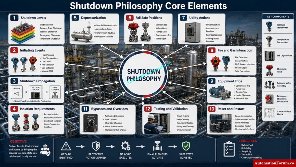
A good Shutdown Philosophy should clearly define:
- Shutdown levels and hierarchy
- Initiating events
- Automatic and manual initiation
- Shutdown propagation
- Isolation requirements
- Depressurization requirements
- Fail safe positions of final elements
- Time delays where justified
- Electrical power actions
- Utility actions
- Fire and Gas interaction
- Package shutdown interfaces
- Operator alarms and indications
- Reset requirements
- Restart permissives
- Startup inhibits
- Maintenance bypasses and overrides
- Testing and proof test considerations
Download Essential Functional Safety Terms Engineers Must Know: Functional Safety Terminology – Excel Download for Industrial Automation
Shutdown Philosophy and Cause and Effect Matrix
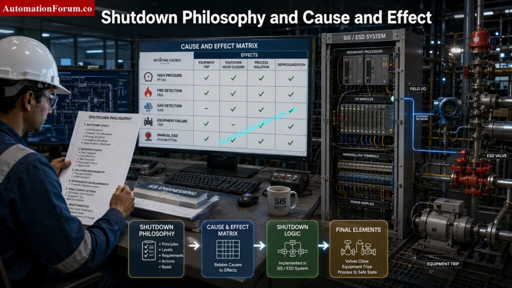
The Shutdown Philosophy establishes the overall engineering intent for protecting the process, while the Cause and Effect Matrix converts that intent into specific initiating causes and resulting actions. Together, they provide the foundation for developing shutdown logic and verifying the required response.
From Shutdown Philosophy to Cause and Effect
Engineers identify the hazardous event, determine its potential consequence and select the appropriate shutdown level. The required protective action is then documented in the Cause and Effect Matrix.
Shutdown Causes and Shutdown Effects
Each cause is linked to defined effects such as equipment trips, process isolation, shutdown valve closure, utility actions or depressurization. This ensures that the intended response is clearly understood across engineering disciplines.
Shutdown Logic Development
The approved Cause and Effect is translated into shutdown logic within the appropriate control or safety system. The logic may include voting arrangements, time delays, permissives, startup inhibits, resets and feedback monitoring.
Shutdown Valve Actions
Shutdown valves provide important final isolation actions during a shutdown. Their required movement, fail safe position, solenoid arrangement and feedback requirements should be consistent with the approved shutdown strategy.
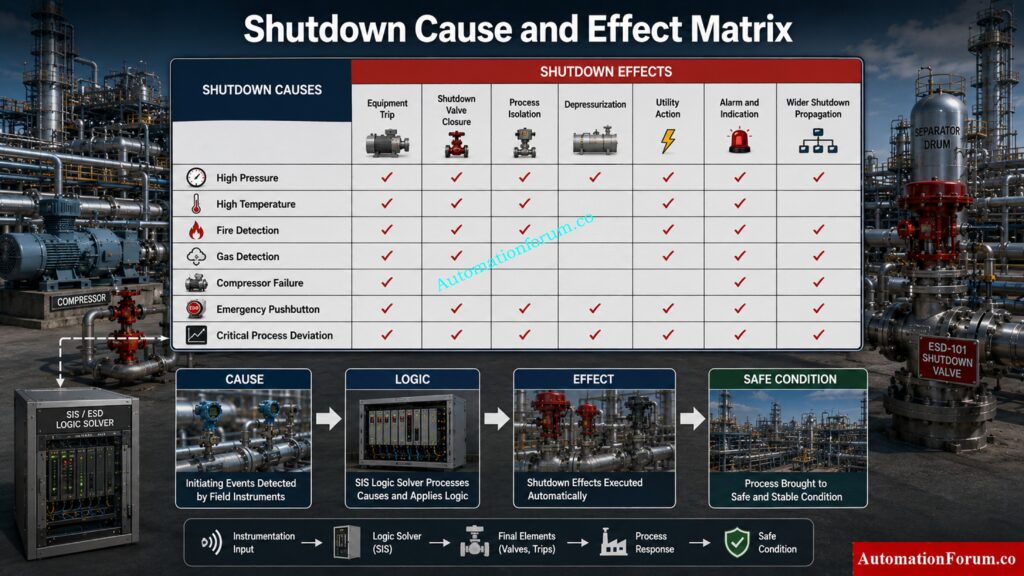
Shutdown Equipment Trips
The Cause and Effect identifies which pumps, compressors, fired equipment and other process equipment must stop for each applicable shutdown condition. Clear definition helps prevent both inadequate protection and unnecessary shutdown propagation.
Shutdown Logic Verification
The implemented logic must be checked against the approved Shutdown Philosophy and Cause and Effect Matrix. During commissioning and validation, engineers verify that the correct initiating signal produces the intended final action.
Test Your SIS Knowledge With These Challenging Questions: Test Your Expertise in Safety Instrumented Systems (SIS): Knowledge Quiz
Shutdown Philosophy and SIS Engineering
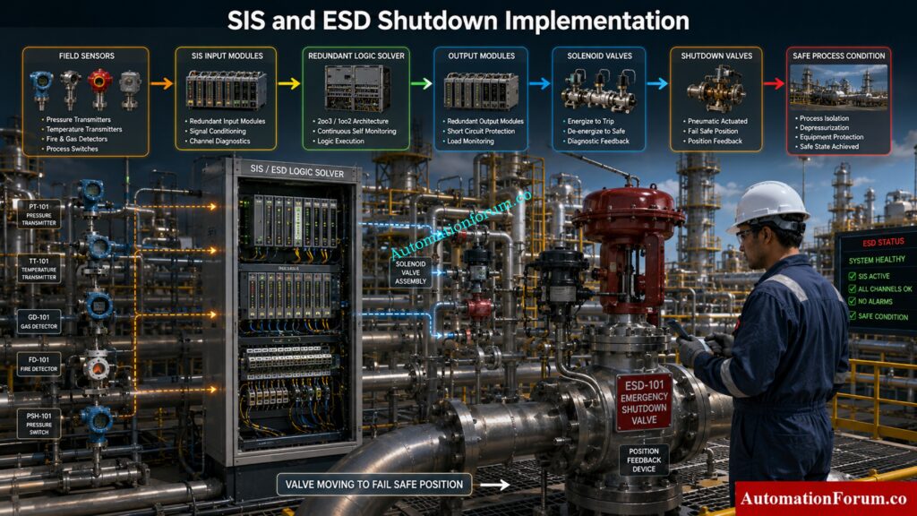
The Shutdown Philosophy provides important engineering input for Safety Instrumented System design by establishing the required protective response.
Safety Instrumented Functions
Applicable safety instrumented functions are identified from process hazards, risk studies and project safety requirements. Each function should have a clearly defined protective purpose.
SIS Input and Output Requirements
Engineers identify the required sensors, input signals, logic solver outputs and final elements. These requirements support the SIS input and output list and detailed instrumentation design.
Logic Solver Actions
The logic solver processes the defined input conditions and executes the approved safety actions. Voting logic, diagnostics, delays and reset behaviour must follow the approved engineering requirements.
Final Element Requirements
Shutdown valves, solenoids and other final elements must move to the required safe condition when the relevant safety function operates. Their response and feedback requirements must be properly defined.
SIS Implementation and Validation
The approved safety requirements are translated into SIS application logic and field implementation. Testing and validation then confirm that the installed system performs the intended safety action.
Shutdown Philosophy Engineering Documentation
The Shutdown Philosophy becomes an important input to several engineering documents used throughout detailed design and implementation.
Safety Requirements Specification
The Safety Requirements Specification defines the required safety functions and performance requirements established through the applicable safety lifecycle activities.
Calculate SIL Performance Before Approving Your Safety Function: SIF PFDavg / SIL Verification – Complete Guide + Online Calculator (IEC 61508 / 61511)
Cause and Effect Matrix
The Cause and Effect Matrix documents the relationship between initiating events and resulting shutdown actions.
Shutdown Logic Diagrams
Shutdown logic diagrams show how causes are processed and how the required equipment and isolation actions are initiated.
SIS Architecture
SIS architecture defines the arrangement of safety system components, interfaces, inputs, outputs and associated system elements.
Know When Testing Deferral Becomes A Serious Safety Risk: Testing and Repair Deferral – IEC Guidelines, Procedure, and Best Practices
Instrument Index and Input Output List
These documents identify the instruments and signals required to implement and monitor the shutdown functions.
P and IDs
P and IDs provide the process and equipment context needed to understand isolation points, shutdown valves, process boundaries and equipment interfaces.
Logic Narratives
Logic narratives explain the intended sequence and behaviour of shutdown functions in a form that supports detailed programming and review.
Shutdown Valve Datasheets
Shutdown valve datasheets define the technical requirements for valves used as final elements, including process conditions and required fail safe behaviour.
Blowdown Valve Datasheets
Blowdown valve datasheets support the detailed design of depressurization functions where blowdown is part of the shutdown strategy.
Fire and Gas Cause and Effect
Fire and Gas Cause and Effect must be coordinated with the shutdown strategy so that relevant detection events produce the intended protective actions.
Commissioning and Validation Documents
Commissioning and validation procedures verify that the installed shutdown system operates according to the approved engineering documentation and intended safety response.
Refer the below link for the Shutdown Maintenance Procedure for Marshalling Cabinets in Process Plant
Shutdown Philosophy Engineering Workflow
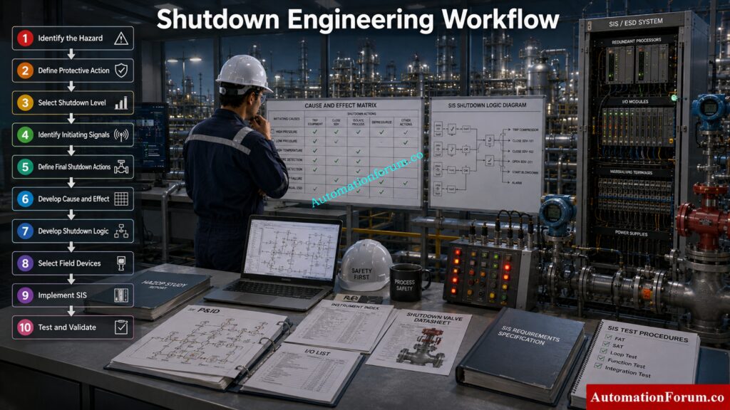
The complete engineering workflow connects the original hazard assessment with the final field implementation.
Identify the Hazard
Review process hazards, operating conditions and applicable safety study findings to identify credible hazardous events.
Define the Required Protective Action
Determine what action is required to move the affected process toward a safe condition and prevent further escalation.
Know When ESD Or SIS Provides The Right Protection: ESD vs SIS Difference When to Use Each and Practical Engineering Guide
Select the Shutdown Level
Select the appropriate shutdown level according to event severity, consequences and project requirements.
Identify Shutdown Initiating Signals
Determine the process measurements, Fire and Gas signals, manual inputs and other conditions that can initiate the shutdown.
Define Final Shutdown Actions
Establish equipment trips, isolation actions, shutdown valve movements, utility actions and depressurization requirements.
Develop the Cause and Effect
Document each initiating cause and its corresponding effects so that all disciplines have a common engineering reference.
Develop Shutdown Logic
Translate the approved Cause and Effect into control or safety system logic, including required voting, delays, permissives and resets.
Select Field Devices
Specify the sensors, shutdown valves, solenoids, feedback devices and associated equipment required for implementation.
Implement the SIS
Where a safety instrumented function is required, implement the approved safety requirements within the designated SIS.
Test and Validate the Shutdown System
Complete inspection, testing, commissioning and validation to confirm that the field system produces the intended shutdown response.
Follow This Essential Instrumentation Turnaround Sequence Before Restart: Instrumentation Shutdown and Turnaround Activity Checklist: A Complete Step-by-Step Procedure
ESD Shutdown Reset and Restart Philosophy
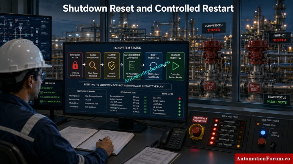
A shutdown is not complete simply because the trip has occurred.
Resetting an ESD should not automatically restart the plant. The initiating condition must first be investigated, the hazard must be removed and the required process conditions must be restored.
The philosophy should define whether reset is manual, local or controlled through a defined reset hierarchy. Restart permissives should confirm that the equipment and process are ready before operation resumes.
This separation between resetting the shutdown system and restarting equipment is important. It prevents an unsafe automatic return to operation after a serious process event.
Practical Shutdown Philosophy Example
Consider an offshore gas compression facility.
Suppose an abnormal compressor condition is detected and the event is limited to the compressor package. The required response may be a Unit Shutdown, allowing other process areas to continue operating.
If a condition develops that affects the complete compression train, the response may escalate to Process Train Shutdown. The relevant train equipment is stopped and the required interfaces are isolated.
If a serious facility wide hazardous event occurs, the response may escalate to Emergency Shutdown. Process equipment is stopped, hazardous inventory is isolated and designated sections may be depressurized according to the project design.
The example demonstrates an important engineering principle: the shutdown response should increase as the potential consequence of the event increases.
See How SOVs Deliver Reliable Emergency Shutdown Protection: Implementing a Solenoid Operated Valve for Emergency Shutdown
Common Shutdown Philosophy Engineering Mistakes
One common mistake is using shutdown terminology inconsistently. Different documents can then assign different meanings to the same shutdown level.
Another problem is failing to define shutdown boundaries. Engineers may know that a train should shut down but not clearly identify the upstream, downstream and utility interfaces.
Confusing a normal process trip with an Emergency Shutdown can also lead to excessive shutdown propagation.
Final element actions must be clearly defined. Unclear valve actions or equipment trip requirements can create major problems during Cause and Effect development and commissioning.
Package systems are another frequent source of interface problems. Vendor shutdown requirements must be reviewed against the overall facility philosophy.
Reset requirements, bypass controls and Fire and Gas interfaces should not be left until late detailed engineering.
Most importantly, the Shutdown Philosophy should be developed using the findings of the relevant hazard studies. If the philosophy and Cause and Effect Matrix disagree, the conflict should be resolved before implementation.
Check Your SIS Against These Critical Compliance Requirements: Advanced Safety Instrumented System (SIS) Inspection Checklist for IEC 61511 Compliance
Why Instrumentation and Control Engineers Must Understand Shutdown Philosophy
Instrumentation and Control Engineers are responsible for translating the shutdown strategy into a system that works correctly in the field.
This requires more than wiring a trip signal or programming a logic block.
Engineers need to understand the purpose of each trip input, voting arrangement, logic solver action, shutdown valve response, solenoid arrangement and feedback signal. They also need to consider manual shutdown facilities, fail safe behaviour, alarms, HMI indications, bypasses and testing requirements.
During commissioning, the engineer must verify that the field response matches the documented Cause and Effect and the approved safety requirements.
Understanding why a shutdown action exists is therefore just as important as understanding how the signal is implemented.
Avoid These Costly SIS Design Errors Before Commissioning: Top Critical Mistakes in Safety Instrumented System Design as per ISA 84 Standard and How to Avoid Them
Shutdown Philosophy Frequently Asked Questions
What is the shutdown process?
The shutdown process is a planned sequence of actions that moves equipment or a process to a defined safe condition. It may include stopping equipment, isolating process sections, maintaining essential utilities and, when required, depressurizing hazardous inventory.
What is ESD in instrumentation?
ESD means Emergency Shutdown. In instrumentation, an ESD system detects defined hazardous or abnormal conditions and initiates predetermined actions such as equipment trips, process isolation and shutdown valve closure to reduce the risk of escalation.
What is the purpose of a shutdown valve?
A shutdown valve isolates process equipment or piping when a defined shutdown condition occurs. It helps stop the flow of hazardous material and supports the process of moving the affected section toward a safe condition.
What are the emergency shutdown procedures for a chemical plant?
Emergency shutdown procedures normally involve identifying the hazardous condition, initiating the appropriate shutdown, stopping affected equipment and isolating hazardous inventory. Depending on the event, depressurization, emergency utilities, Fire and Gas actions and controlled evacuation may also be required.
What is an emergency shutdown system?
An Emergency Shutdown System is a protective system designed to detect specified hazardous conditions and take predetermined actions to bring the process toward a safe state. It can initiate equipment shutdown, process isolation, shutdown valve closure and depressurization where required.
What is meant by shutdown project?
A shutdown project is a planned period in which a plant or part of a plant is taken out of normal operation to perform activities such as inspection, maintenance, repair, modification and testing. It is normally planned carefully because production is interrupted and many activities must be coordinated.
What is the purpose of a shutdown valve?
The primary purpose of a shutdown valve is to quickly isolate a process section when a defined shutdown condition occurs. This can limit hazardous material flow and prevent the initiating event from escalating into a larger incident.
What’s the difference between a shutdown and a turnaround?
A shutdown normally refers to stopping a process or equipment because of an operational, maintenance or safety requirement. A turnaround is a larger planned plant outage that can include shutdown, inspection, maintenance, statutory work, equipment replacement and modifications.
What does shutdown system mean?
A shutdown system is the combination of instruments, logic, final elements and supporting functions used to bring equipment or a process to a safe condition when defined abnormal or hazardous conditions occur. An ESD or SIS may form part of the overall shutdown system depending on the facility design.
What is the difference between ESD and SIS?
ESD refers to the emergency shutdown function used to bring a process to a safe condition during hazardous events. SIS is the broader safety instrumented system that performs defined safety instrumented functions, which can include shutdown functions.
What is a shutdown philosophy document?
A Shutdown Philosophy document defines the overall strategy for shutting down equipment, process units, trains or an entire facility. It establishes shutdown levels, initiating events, isolation requirements, shutdown actions, reset requirements and restart principles.
What is a shutdown level hierarchy?
A shutdown level hierarchy defines progressively wider protective actions based on the severity of an event. A typical hierarchy may include Unit Shutdown, Process Train Shutdown, Process Shutdown, Emergency Shutdown and Total Platform Shutdown, although terminology varies by project.
What is the difference between process shutdown and emergency shutdown?
A Process Shutdown generally stops the process in response to defined abnormal conditions while selected utilities may remain available. An Emergency Shutdown is intended for more serious hazardous events and may include wider isolation, equipment shutdown and depressurization.
What is a shutdown Cause and Effect Matrix?
A shutdown Cause and Effect Matrix defines the relationship between initiating conditions and the actions that must occur. It converts the engineering intent established in the Shutdown Philosophy into specific shutdown actions for detailed system design.
What is shutdown logic?
Shutdown logic is the control and safety logic that determines what actions occur when a defined shutdown condition is detected. It can include voting logic, equipment trips, shutdown valve commands, delays, permissives, resets and feedback monitoring.
What is the role of shutdown valves in an ESD system?
Shutdown valves act as final elements that isolate process flow when an ESD action is initiated. Their fail safe position and response must be consistent with the process safety requirements and the approved shutdown philosophy.
Why is shutdown reset important?
Resetting a shutdown should not automatically restart the affected process or equipment. The initiating cause must be investigated and safe operating conditions restored before the system is reset and the equipment is restarted through the required permissives.
What is shutdown propagation?
Shutdown propagation defines how a shutdown in one equipment item or process area affects connected equipment and other process sections. Proper propagation prevents unnecessary plant wide trips while ensuring that hazardous conditions are adequately isolated.
What is the difference between shutdown and trip?
A trip usually refers to an automatic protective action that stops a specific piece of equipment or process function. A shutdown can involve a wider coordinated sequence affecting equipment, process sections or an entire facility.
Learn How Transmitter Voting Strengthens Safety System Reliability: Redundant Transmitters Explained: Reliability, Voting Logic and SIL for Instrumentation Engineers
Shutdown Philosophy: From Process Safety to ESD and SIS Implementation
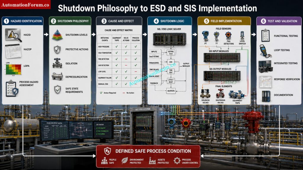
The Shutdown Philosophy is one of the foundation documents connecting process hazard identification with practical SIS and ESD implementation.
Good shutdown engineering is not about shutting down everything whenever a problem occurs. It is about selecting the correct level of action, isolating the hazard, preventing escalation, protecting people and assets and providing a controlled path toward recovery.
The philosophy provides the engineering basis for Cause and Effect development, shutdown logic, SIS design, field implementation, testing and commissioning.
For Instrumentation and Control Engineers, understanding this document is essential because every shutdown signal and final action should have a clear engineering reason behind it.
A well developed Shutdown Philosophy ensures that when the process moves outside its safe operating limits, the plant takes the right action, at the right level, for the right reason.
Refer the below link for the Process Safety vs Functional Safety: Key Differences, SIS, SIF, SIL & IEC 61511 Guide
