
- What Is a Cable Shield and Why Is It Used?
- Shield Grounding Versus Shield Bonding
- How Does Electrical Noise Enter Instrumentation Cables?
- Protective Earth and Functional Earth in Instrumentation
- Should Cable Shields Be Grounded at One End or Both Ends?
- Where Should Shields Be Terminated for Analog Instrumentation Signals?
- Where Should Shields Be Terminated for Digital and Communication Cables?
- Individual Pair Shielding and Overall Cable Shielding
- How Should Cable Shields Be Terminated at Junction Boxes?
- How Should Cable Shields Be Terminated Inside Control Panels?
- Cable Shield Termination Methods
- Common Cable Shield Termination Mistakes
- How to Select the Correct Cable Shield Termination Point
- Practical Examples of Cable Shield Termination
- What Should You Check During Cable Shield Commissioning?
- Cable Shield Termination Decision Guide
- Frequently Asked Questions About Cable Shield Termination
- Conclusion: Key Takeaways for Proper Cable Shield Termination
Should Cable Shields Be Grounded at One End or Both Ends?
Cable shield termination is one of those instrumentation details that looks simple until a plant starts experiencing unstable readings, communication failures, unexplained PLC input errors, or intermittent noise. Engineers often ask the same question: should the shield be grounded at one end or both ends?
There is no universal answer.
The correct cable shield termination depends on the signal type, interference frequency, cable construction, grounding arrangement, communication protocol, equipment manufacturer requirements, and EMC design. Low frequency analog instrumentation circuits are commonly treated differently from high frequency communication systems. The objective is always to provide effective shielding without creating unwanted circulating currents.
What Is a Cable Shield and Why Is It Used?
How Does a Cable Shield Reduce Electrical Noise?
Cable shield A conductive coating enclosing the signal conductors. Common constructions include foil, braided metal, spiral metal shielding and combinations of these layouts. The shield prevents electromagnetic interference and electrostatic interference from coming in contact with the wires. It can also reduce electromagnetic radiation produced by the cable itself.
In an instrumentation cable, the shield provides a controlled path for unwanted electrical energy rather than allowing that energy to couple directly into the signal circuit.
Why Is Proper Shield Termination Important?
However, the effectiveness of a shield depends on the right design of its termination. Excessive exposed conductor, poor continuity, or a long connection between the shield and its intended bonding point can reduce shielding effectiveness, especially at higher frequencies. For demanding EMC applications, a low impedance connection around the cable circumference is often preferred.
Refer the below link for the Shield Grounding Noise Calculator for Instrumentation: A Practical Engineer Guide
Shield Grounding Versus Shield Bonding
What Is Shield Grounding?
Shield grounding generally refers to connecting the cable shield to a designated earth or functional grounding point.
What Is Shield Bonding?
Shield bonding refers more broadly to establishing a low impedance electrical connection between the shield and the equipment or bonding system.
Why Does Shield Connection Impedance Matter?
This distinction becomes important at higher frequencies. A connection can have very low resistance but still have significant impedance because of inductance. This is why a long drain wire may not provide the same EMC performance as a short, wide or circumferential shield connection.
The termination method must therefore be selected according to the electrical frequency involved and the EMC objective of the system.
Discover Why Shield Grounding Must Stay Under Control: Why the Cable Shield is Grounded Only at the PLC or Control Panel Side
How Does Electrical Noise Enter Instrumentation Cables?
What Is Capacitive Coupling?
Electrical noise can reach an instrumentation cable through several coupling mechanisms.
Capacitive coupling occurs when a changing voltage from a nearby circuit transfers unwanted energy into the signal conductors. This can happen when instrumentation cables run close to power cables.
What Is Inductive Coupling?
Inductive coupling occurs when changing current creates a magnetic field that induces voltage into nearby conductors. Motors, transformers and high current circuits are common sources.
Terminate Instrument Cables Correctly Every Single Time: Method Statement for Instrumentation Cable Termination
Electromagnetic and radio frequency interference can come from switching equipment, variable frequency drives, contactors, relays, power supplies and communication equipment.
Can Cable Shielding Alone Eliminate Electrical Noise?
Cable shielding helps, but shielding alone is not enough. Good cable routing, physical separation, twisted pairs, proper bonding, correct grounding and suitable equipment installation are equally important.
Master Instrument Cable Shielding Before Noise Causes Failures: What is instrument cable shielding?
Protective Earth and Functional Earth in Instrumentation
Protective earth and functional earth should not automatically be considered interchangeable.
Protective earth is primarily associated with electrical safety, exposed conductive parts and fault protection. Functional earth can be used where an earth connection is required for the proper operation or EMC performance of equipment.
A cable shield may be connected to a designated functional earth or shield termination system when the project design specifies it. It should not simply be connected to the nearest protective earth terminal without checking the system grounding philosophy.
This is particularly important inside PLC, DCS and SIS cabinets where separate grounding arrangements may exist.
Measure Signal Quality Before Noise Ruins Control Performance: Signal-to-Noise Ratio (SNR) Calculator for Instrumentation and Control Systems
Should Cable Shields Be Grounded at One End or Both Ends?
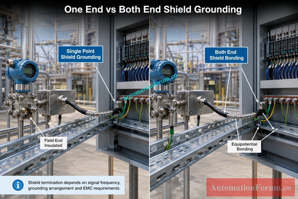
The answer depends on the application.
When Should a Cable Shield Be Grounded at One End?
Single point shield grounding is commonly used for some low frequency analog instrumentation circuits. Connecting the shield at one designated location reduces the possibility of circulating shield current caused by a ground potential difference between two locations. The unused shield end is normally insulated so it cannot accidentally contact another grounding point.
Avoid Hazardous Area Gland Mistakes That Create Serious Risks: Cable Gland Selection for Hazardous Area Installations – Complete Guide
When Should a Cable Shield Be Grounded at Both Ends?
Both end shield bonding can provide better performance against high frequency interference because it can provide a low impedance path for unwanted high frequency current. It is commonly used for certain communication and EMC applications when the grounding and bonding system is designed to support it.
Why Is Both End Shield Bonding Used for High Frequency EMC?
The important point is that both end bonding should not be applied blindly. If two grounding locations have a significant potential difference, shield current can flow through the shield.
Therefore, the decision should be based on the complete system design rather than the simple rule that shields must always be grounded at one end or always at both ends.
Catch Unstable Signals During Real Running Plant Inspections: Noise and Signal Stability Observation for Running Inspection in Instrumentation and Control Systems
Where Should Shields Be Terminated for Analog Instrumentation Signals?
For many 4 to 20 mA circuits, low level analog signals, thermocouples, RTD circuits and analyzer signals, the project design may specify shield termination at one designated end.
In many process plants, this point is the receiving equipment side, such as the marshalling cabinet, control panel, DCS cabinet or PLC cabinet. The field instrument end is then insulated when the single point grounding philosophy is being used.
For example, a pressure transmitter connected to a DCS analog input may have the cable shield terminated at the designated panel grounding arrangement while the transmitter end remains insulated.
The actual termination must follow the project earthing philosophy, loop drawings, cable schedule, vendor instructions and applicable engineering standards.
Never connect the shield to signal common simply because a spare terminal is available. The shield connection is part of the grounding and EMC design and should connect to the intended earth or functional grounding arrangement.
Verify Every 4 to 20 mA Loop Before Commissioning: Live Signal Verification 4 to 20 mA Loop Standard Operating Procedure (SOP)
Where Should Shields Be Terminated for Digital and Communication Cables?
Communication cables require more careful consideration because their signals contain higher frequency components.
Profibus, RS 485, industrial Ethernet and other communication systems may specify particular shield bonding arrangements. Many communication systems benefit from bonding the shield at both ends when a suitable equipotential bonding system exists.
The purpose is to maintain a low impedance shielding path and reduce high frequency interference. The exact method is protocol and manufacturer specific.
An analog instrumentation cable rule should therefore never be copied directly into a communication network design. Follow the communication protocol installation guide, equipment manual, cable specification and project EMC requirements.
Refer the below link for theUnderstanding the Difference Between Live Zero and Dead Zero in 4 to 20 mA Signals
Individual Pair Shielding and Overall Cable Shielding
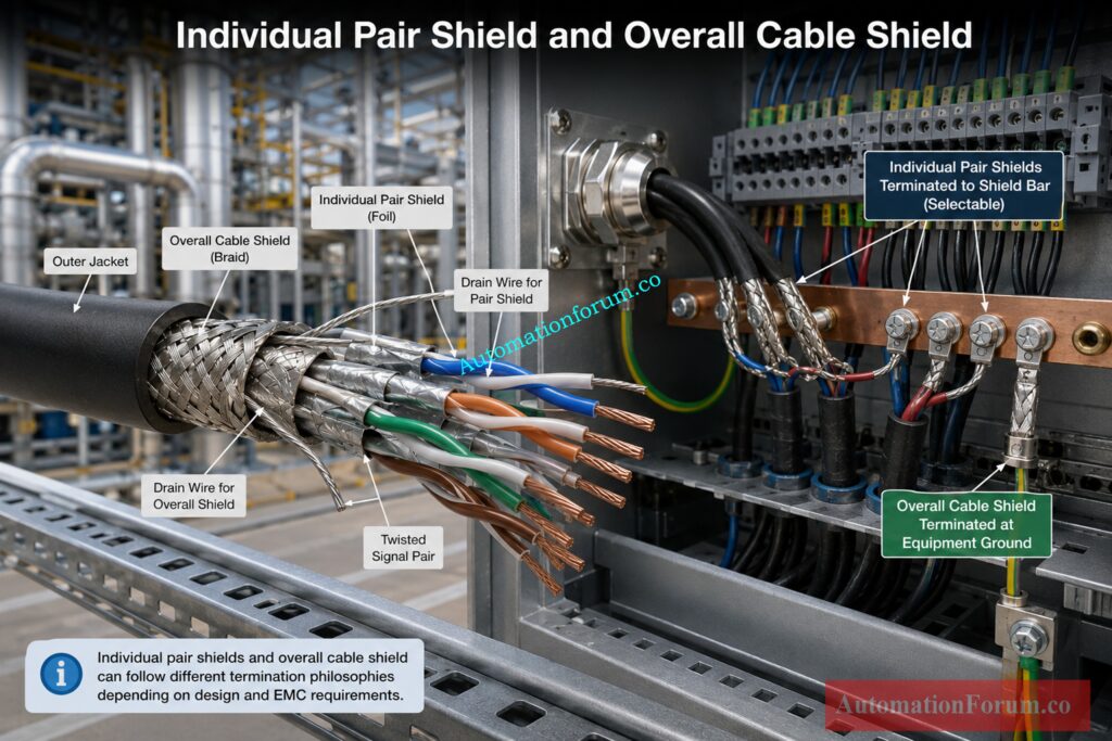
A multicore instrumentation cable may contain several twisted pairs, with each pair having its own shield. The cable may also have an overall shield around all the pairs. Both shield you from electrical interference. But they aren’t necessarily one and the same.
What Is Individual Pair Shielding?
One signal pair within the cable is individually shielded. This helps safeguard that particular transmission from electrical noise and reduces interference between surrounding signal circuits.
This is especially handy if you have to run numerous sensitive analog signals through the same multicore cable. The individual shield prevents undesired electrical noise in one circuit from impacting another circuit.
What Is an Overall Cable Shield?
The entire set of conductors or separately shielded pairs is enclosed by an overall cable shield. It provides an additional layer of protection from electromagnetic interference from outside the cable.
For example, if the instrumentation cable is located near power cables, motors or variable frequency drives, the overall shield can provide additional protection if appropriately terminated and bonded.
Troubleshoot 4 to 20 mA Loops Faster With Confidence: How to do troubleshooting of a 4-20mA loop?
Can Individual and Overall Shields Have Different Terminations?
Yes. The individual pair shields and the overall cable shield do not always have to be terminated in the same way.
In some instrumentation installations, the individual pair shields may be connected at one designated point, while the overall shield may have a different bonding arrangement. This depends on the cable design, grounding philosophy and EMC requirements of the installation.
What Should Engineers Check Before Terminating the Shields?
Do not assume that every shield inside a multicore cable should be connected to the same grounding point. First check the cable manufacturer’s instructions, project grounding philosophy, wiring drawings and equipment requirements.
This small detail can make a significant difference when troubleshooting noisy analog signals or communication problems in the field.
This version sounds more like an experienced instrumentation engineer explaining the issue to another engineer, rather than a textbook definition.
Discover Why 4 to 20 mA Remains Industry Standard: Why Engineers Still Trust the 4-20 mA Signal in Automation Systems
How Should Cable Shields Be Terminated at Junction Boxes?
When a shielded instrumentation cable passes through a junction box, shield continuity is normally maintained when the design requires a continuous shield path.
The shield should not automatically be connected to the local junction box earth.
For a single point grounding arrangement, the shield may pass through the junction box using suitable shield continuity terminals while remaining isolated from the junction box earth.
This prevents the junction box from becoming an unintended grounding point.
Good documentation is important. The cable schedule, termination drawing and junction box wiring drawing should clearly identify how each shield is handled.
Choose the Right Twisted Pair Before Signal Problems Begin: Twisted Pair Cable in Industrial Signal Transmission: The Essential Guide for 4-20 mA and RS 485 Systems
How Should Cable Shields Be Terminated Inside Control Panels?
Inside control panels, marshalling cabinets, PLC cabinets, DCS cabinets and SIS cabinets, shields may be connected to a dedicated shield bar or specified functional earth arrangement.
For low frequency applications, a short drain wire may be suitable when the project design permits it.
For high frequency EMC applications, a 360 degree shield termination or suitable shield clamp can provide a much lower impedance connection than a long drain wire.
A long pigtail can behave inductively at high frequencies. This means a connection that appears electrically adequate at low frequency may become much less effective when the interference frequency increases.
The shield should also be stripped back only as much as necessary. Maintaining the shield as close as practical to the equipment entry helps preserve shielding effectiveness.
Fix Grounding and Bonding Mistakes Before Equipment Fails: Grounding and Bonding in Instrumentation and Control Systems
Cable Shield Termination Methods
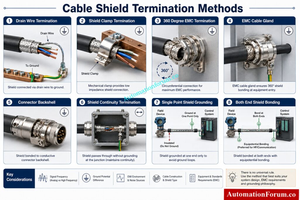
Drain Wire Shield Termination
A drain wire provides a practical connection to the cable shield. It is commonly used in instrumentation cables where the design calls for a simple shield connection.
Its limitation is that the connection may have higher impedance at high frequencies compared with a short circumferential bond.
Shield Clamp Termination
A shield clamp provides a direct connection between the shield and the intended bonding point. It can be useful where low impedance EMC performance is required.
360 Degree EMC Shield Termination
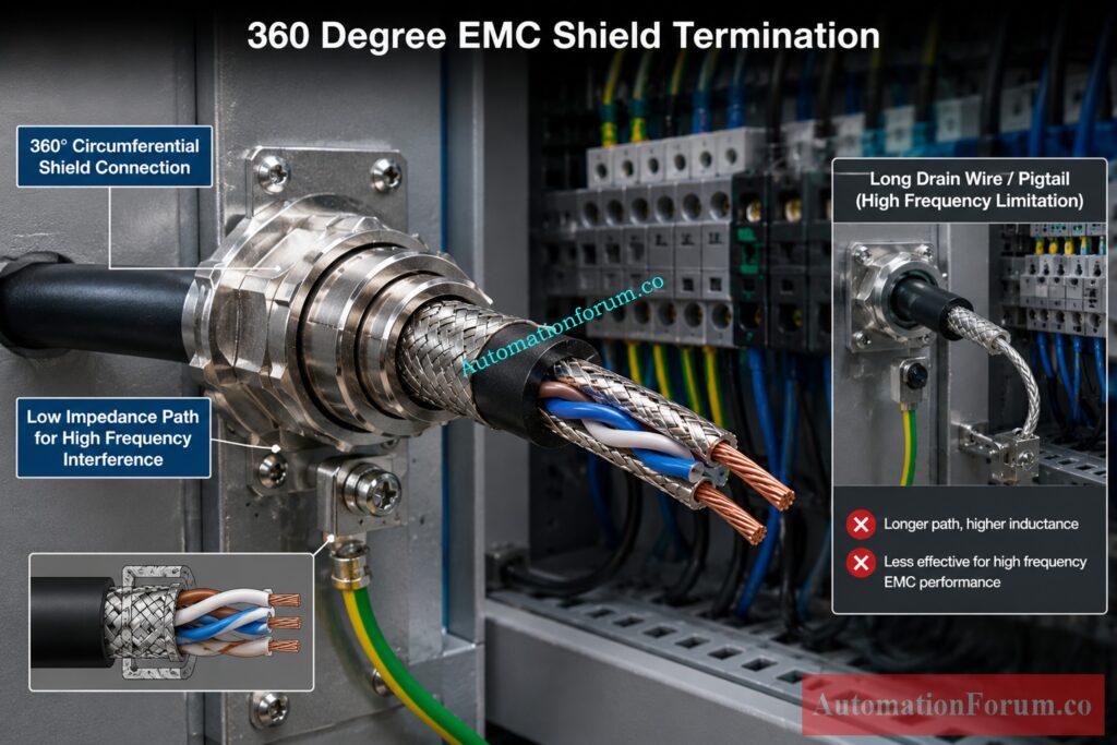
A suitable EMC cable gland can bond the shield around the cable circumference. This provides a low impedance path and is particularly useful for high frequency interference control.
EMC Cable Gland Shield Termination
In communication and electronic equipment, the shield can be connected to a conductive connector backshell. This maintains shielding close to the equipment entry.
Connector Backshell Shield Termination
Where a cable passes through a junction box or intermediate termination point, the shield can be maintained continuously without creating an additional earth connection.
Shield Continuity Termination
This method connects the shield to ground at one designated location. It is commonly considered for suitable low frequency analog applications where ground potential differences are a concern.
Both End Shield Bonding
Both end bonding can provide strong high frequency EMC performance when the grounding system provides suitable equipotential bonding.
Engineered Hybrid Shield Termination
Capacitive or other engineered shield arrangements can sometimes be used for specific EMC requirements. These should not be introduced as field modifications without an engineering basis or manufacturer approval.
Know Which Fault Type Can Threaten Your System: Difference between Earth Fault and Ground Fault
Common Cable Shield Termination Mistakes
- Grounding an analog shield at several locations without checking the grounding design.
- Leaving a shield floating when the system design requires a grounding connection.
- Connecting the shield directly to signal common.
- Grounding every shield inside every junction box.
- Using long pigtails where high frequency EMC performance is required.
- Removing excessive shield length during termination.
- Breaking shield continuity at cable joints.
- Applying analog grounding practices to communication networks.
- Ignoring equipment manufacturer instructions.
- Ignoring ground potential differences between equipment locations.
- Assuming protective earth and functional earth always have the same purpose.
How to Select the Correct Cable Shield Termination Point
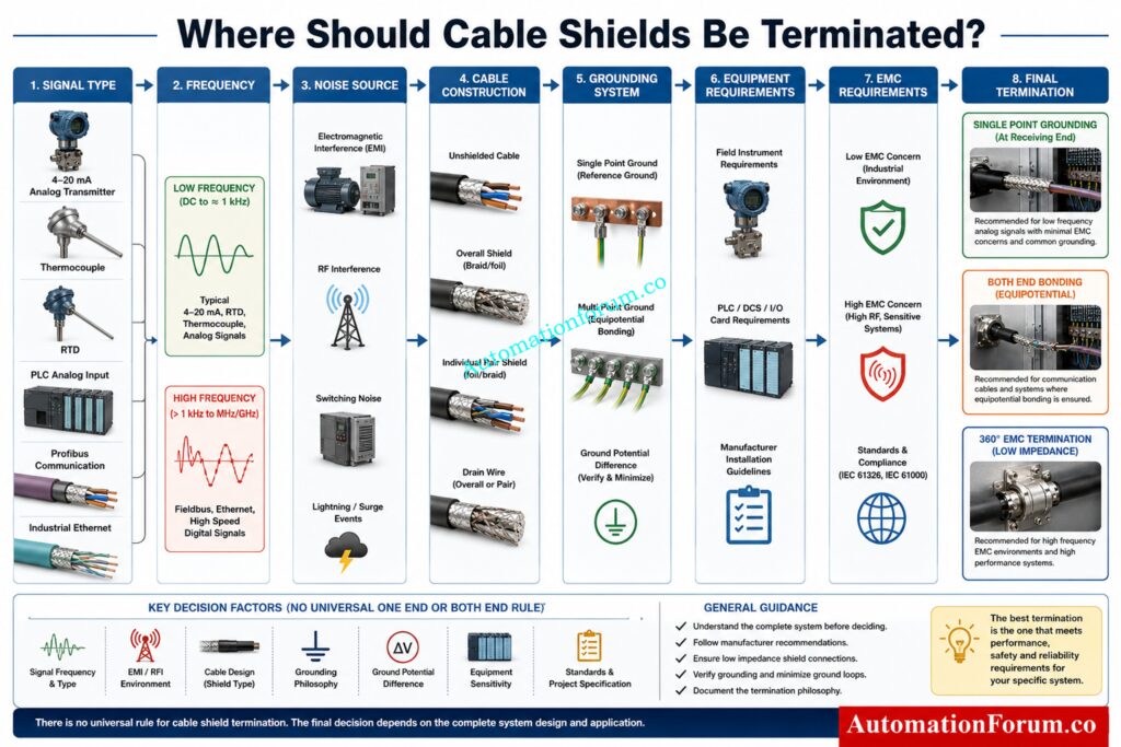
Before terminating an instrumentation cable shield, check the following engineering factors.
- Identify the signal type.
- Determine whether the circuit is analog or digital.
- Consider the signal and interference frequency.
- Identify local sources of noise, such as motors, variable frequency drives, etc.
- Check the cable construction.
- Determine whether the cable has individual pair shields, an overall shield or both.
- Check the communication protocol requirements where applicable.
- Review equipment manufacturer instructions.
- Review the project earthing and grounding philosophy.
- Check the control system vendor requirements.
- Consider ground potential differences.
- Review EMC requirements.
- Check cable routing and separation from power cables.
The final shield termination decision should be made from the complete system design, not from a single general rule.
See Why Current Signals Beat Voltage in Industry: Why 4-20 mA Current Signal is Preferred Over Voltage Signal in Instrumentation?
Practical Examples of Cable Shield Termination
Example 1: 4 to 20 mA Pressure Transmitter
A pressure transmitter sends a 4 to 20 mA signal to a DCS input. If the project uses single point shield grounding for analog loops, the shield may be terminated at the designated DCS or marshalling cabinet grounding point and insulated at the field instrument.
Example 2: Thermocouple Cable
A thermocouple signal is relatively small and can be sensitive to electrical interference. Shield termination should follow the temperature system manufacturer instructions and project grounding philosophy. The shield arrangement should be selected with attention to the measurement system and surrounding noise sources.
Example 3: Profibus Communication Cable
Profibus uses high speed communication and requires careful attention to shielding and bonding. The shield arrangement should follow the Profibus installation requirements and equipment manufacturer instructions. Where both end bonding is specified, equipotential bonding becomes especially important.
Example 4: Instrumentation Cable Near a VFD
An instrumentation cable routed close to a variable frequency drive may experience significant high frequency interference. In this situation, proper routing and separation should be reviewed first. Where the EMC design requires it, a low impedance shield connection such as a suitable 360 degree termination can provide better high frequency protection than a long drain wire.
Example 5: PLC Analog Input
Consider a pressure transmitter connected to a PLC analog input through a field junction box.
The complete circuit is:
Field transmitter to junction box to control panel to PLC analog input.
Suppose the project grounding philosophy specifies single point grounding for the analog signal shield.
The shield may remain continuous through the junction box and be terminated at the designated shield bar or grounding arrangement inside the control panel.
The field end is insulated from accidental contact.
The important point is that the junction box should not automatically become another shield grounding point.
During commissioning, the engineer should verify shield continuity, the designated grounding point and the absence of unintended connections.
Example 6: SIS Signal Cable
Safety instrumented systems require particular discipline because the wiring arrangement is part of an approved system design.
For SIS signal cables, shield termination should follow the safety system manufacturer’s requirements, project specifications and approved engineering drawings.
A maintenance engineer should not change a shield connection simply because a signal appears noisy.
The correct approach is to first investigate cable routing, grounding, shield continuity, interference sources and the approved wiring philosophy.
Any modification to an SIS installation should follow the applicable management and approval process.
Example 7: Analyzer Signal Cable
Analyzer systems often contain sensitive measurement circuits and may have vendor specific cable requirements.
An analyzer cable can carry low level signals that are more susceptible to electrical interference than a conventional 4 to 20 mA loop.
Before terminating the shield, check the analyzer manufacturer’s wiring instructions. Some analyzer systems may specify particular grounding points, shield arrangements or separation requirements.
Do not assume that the shield termination used for a nearby transmitter loop is automatically suitable for an analyzer.
Simulate Accurate 4 to 20 mA Signals Like Professionals: How to simulate 4-20ma signal with Loop Calibrator ?
What Should You Check During Cable Shield Commissioning?
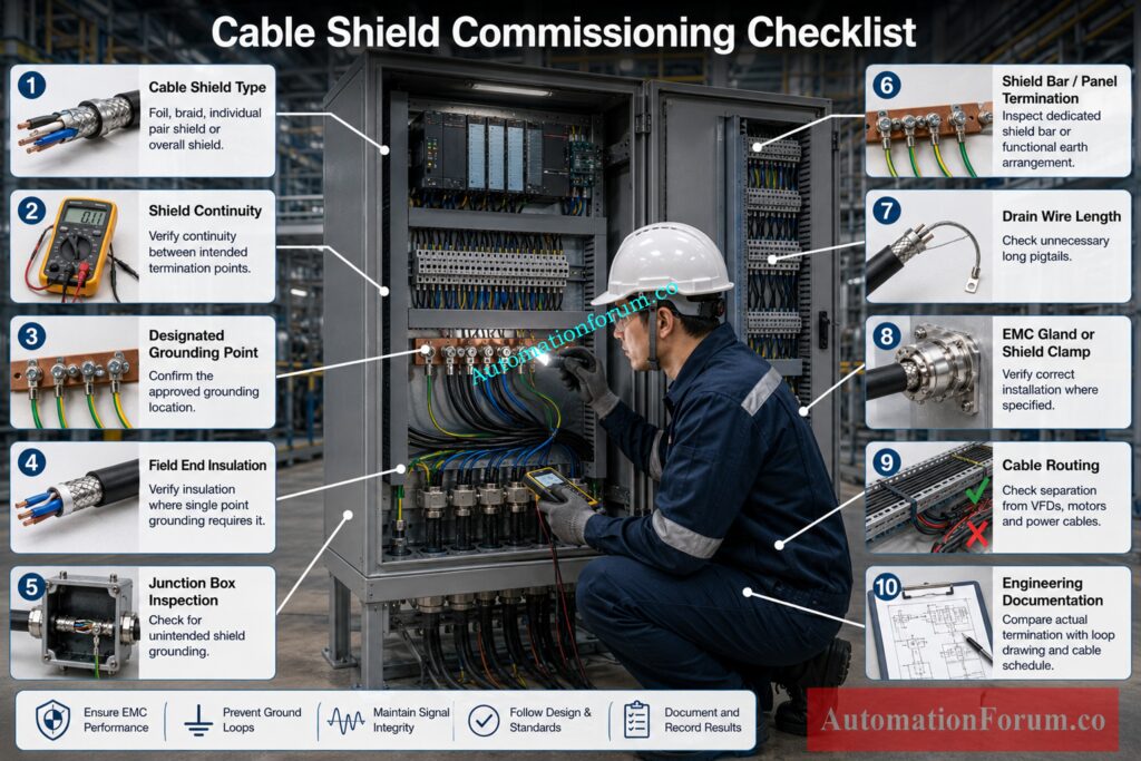
A practical shield termination inspection should include the following checks.
- Confirm the cable shield type.
- Confirm whether the cable has individual pair shields, an overall shield or both.
- Continuity of shield from intended points – Check
- Verify the assigned ground position.
- Ensure that the field end is insulated if necessary.
- Verify that there is no incidental shield contact inside junction boxes.
- Inspect control panel shield bar or termination fixture.
- Check length of drain wire.
- Check EMC gland or shield clamp installation if applicable
- Check cable routing around VFDs, motors and power cables.
- Verify the actual termination against the loop drawing and cable schedule.
- Review manufacturer requirements before making any modification.
Discover Why 4 to 20 mA Beats Older Standards: Why not use 0-20mA & 0-15psi instead of 4-20mA & 3-15psi?
Cable Shield Termination Decision Guide
The following decision process provides a practical starting point.
| Engineering factor | What to consider |
| Signal type | Analog, digital or communication |
| Signal frequency | Low frequency or high frequency |
| Interference | Low frequency noise, switching noise or RF interference |
| Cable construction | Foil, braid, individual pair shield or overall shield |
| Grounding system | Single point or equipotential bonding arrangement |
| Ground potential | Possible voltage difference between locations |
| Equipment | PLC, DCS, SIS, transmitter or analyzer |
| Protocol | Follow communication specific requirements |
| EMC requirement | Standard drain connection or low impedance termination |
| Installation | Cable routing and proximity to power equipment |
The final shield termination point should be selected only after considering these factors together.
Select the Correct Cable Gland Without Guesswork: Instrument Cable Gland Selector Calculator Guide
Frequently Asked Questions About Cable Shield Termination
Where should an instrumentation cable shield be grounded?
The shield should be terminated at the location specified by the project grounding philosophy, equipment requirements and EMC design.
For many suitable analog circuits, this is one designated grounding point, often at the receiving equipment end.
Should cable shields be grounded at one end or both ends?
There is no universal rule because the correct method depends on signal frequency, grounding arrangement and EMC requirements.
Single point grounding may suit some analog circuits, while both end bonding can improve high frequency EMC performance.
Why are cable shields grounded at one end for some analog signals?
Single point grounding can reduce circulating shield currents caused by ground potential differences between two grounding locations.
This approach is commonly considered for suitable low frequency analog instrumentation circuits.
Can I connect a cable shield to signal ground?
The cable shield should not normally be connected to signal common simply because a terminal is available.
Connect it to the designated earth or functional earth arrangement specified by the system design.
Should the shield be grounded inside a junction box?
Not automatically, because doing so can create an unintended additional grounding point.
If shield continuity is required, maintain the shield through the junction box according to the approved wiring design.
How should a cable shield be terminated in a PLC panel?
Terminate the shield according to the PLC manufacturer requirements and project EMC philosophy.
A dedicated shield bar, functional earth connection or suitable shield clamp may be used where specified.
Why is a 360 degree shield connection important?
A 360 degree termination provides a low impedance connection around the cable circumference.
This is particularly effective for maintaining shield performance against high frequency electromagnetic interference.
What happens if a cable shield is left floating?
An intentionally insulated shield end can be correct when single point grounding is specified by the design.
An accidentally disconnected shield, however, can reduce shielding effectiveness and cause interference problems.
Choose Ex Zone Cables Without Risking Compliance Failures: What Cables to Use in Ex Zones: Complete Guide for Instrumentation & Control Engineers
Should a 4 to 20 mA cable shield be grounded at one end?
For many suitable low frequency analog circuits, the shield may be grounded at one designated end.
The final arrangement must follow the project grounding philosophy and equipment manufacturer requirements.
Should Profibus cable shields be grounded at both ends?
Many Profibus installations use shield bonding at both ends to provide effective high frequency EMC protection.
The exact termination must follow the Profibus installation requirements and equipment manufacturer’s instructions.
Can cable shields cause ground loops?
Yes, multiple shield grounding points can allow circulating current when grounding locations have different electrical potentials.
The grounding arrangement should therefore be selected according to the complete system design.
Is a drain wire suitable for every shielded cable?
No, a drain wire is suitable for some instrumentation applications but is not ideal for every EMC requirement.
High frequency applications may require a shorter, lower impedance or 360 degree shield termination.
Where should the shield be connected in a control panel?
Connect the shield to the designated shield bar or grounding arrangement required by the project and equipment manufacturer.
Avoid connecting it randomly to signal common or any convenient earth terminal.
How to terminate shielded VFD cable?
Shielded VFD cable should normally use a termination method that maintains effective EMC bonding, often with a suitable EMC gland or 360 degree shield connection.
Follow the VFD manufacturer’s installation requirements and maintain proper bonding and cable routing.
Should shielded cable be grounded at both ends?
It depends on the application, because both end bonding can improve high frequency EMC performance but may create circulating current where ground potential differences exist.
Follow the equipment, cable and project grounding requirements rather than applying a universal rule.
How do you terminate an armoured cable?
Terminate an armoured cable using the specified gland and bonding arrangement so the armour and shield have the required electrical continuity.
The exact method depends on the cable construction, equipment enclosure and applicable earthing and EMC requirements.
Where should a 4/20mA cable shield be grounded?
A 4 to 20 mA cable shield is often grounded at one designated end for suitable analog instrumentation circuits.
The actual termination point should follow the approved loop drawing, grounding philosophy and equipment requirements.
How to properly terminate shielded cable?
Proper termination means maintaining shield continuity and connecting the shield to the intended grounding or bonding point without unnecessary exposed shield.
For high frequency EMC applications, employ a low impedance termination as indicated, e.g. an appropriate 360 degree connection.
Size Cable Trays Correctly Before Installation Problems Escalate: Cable Tray Sizing Calculator: Complete Engineering Guide for IEC 61537 and NEC 392 Compliance
Conclusion: Key Takeaways for Proper Cable Shield Termination
Proper termination of the cable shield is an engineering decision and not a blanket wiring requirement. The correct method depends on signal characteristics, interference frequency, cable construction, grounding architecture, EMC requirements, equipment design and manufacturer instructions.
For some low frequency analog instrumentation circuits, single point grounding can help avoid unwanted circulating currents. For high frequency communication and EMC applications, both end bonding or a low impedance circumferential connection may be more appropriate when the grounding system supports it.
Before making the final shield termination decision, review the project specification, cable schedule, loop drawings, control system documents, communication requirements and grounding philosophy. That approach prevents many noise problems before commissioning begins.
Refer the below link for the Single Point vs Multiple Point Grounding in Instrumentation Systems: Complete Guide for Engineers
