
- Understanding the SIL Verification Report
- What is a SIL Verification Report
- Objectives of a SIL Verification Report
- Typical Contents of a SIL Verification Report
- Safety Instrumented Function Verification Example
- SIF Verification Example Table
- SIL Verification Calculations Explained
- Engineering Inputs and Outputs for SIL Verification
- Best Engineering Practices for SIL Verification
- Common Challenges During SIL Verification
- Benefits of a SIL Verification Report
- Frequently Asked Questions (FAQs) About SIL Verification Report
- Conclusion: Why a SIL Verification Report is Essential for Functional Safety
Understanding the SIL Verification Report
A SIL Verification Report is one of the most important engineering documents produced during the implementation of a Safety Instrumented System. It provides documented evidence that every Safety Instrumented Function has been designed to achieve the required Safety Integrity Level defined during the hazard and risk assessment process.
In functional safety projects, identifying a risk is only the beginning. Engineers must also prove that the selected safety design is capable of reducing that risk to an acceptable level. This proof is provided through the SIL Verification Report.
The report forms an essential part of the Functional Safety Lifecycle described in IEC 61511 and is supported by the equipment requirements defined in IEC 61508. Normally it is prepared whilst the engineering is complete but before the start of commissioning activities.
It is necessary to verify each Safety Instrumented Function, as the mere selection of certified equipment does not guarantee compliance. The complete safety loop, including sensors, logic solver, final element, architecture, diagnostic capability, proof testing strategy, and reliability data, must collectively satisfy the required SIL. A properly prepared SIL Verification Report gives project teams confidence that the installed safety functions can perform as intended throughout the operating life of the plant.
Refer the below link for the Intrinsic Safety Entity Parameter Calculator for Reliable Hazardous Area Loop Design
What is a SIL Verification Report
Definition of a SIL Verification Report
A SIL Verification Report, also known as a Safety Integrity Level Verification Report, is an engineering document that demonstrates whether each Safety Instrumented Function meets its required Safety Integrity Level.
Purpose of a Safety Integrity Level Verification Report
Its primary purpose is to verify that the complete Safety Instrumented System has sufficient reliability and integrity to reduce process risks to an acceptable level. The report evaluates equipment architecture, failure rates, diagnostic capabilities, proof testing intervals, repair assumptions, and overall system performance.
SIL Verification Report vs SIL Determination
Many engineers confuse SIL Verification with SIL Determination, although they serve different purposes. SIL Determination identifies the required level of risk reduction for a safety function. SIL Verification confirms that the detailed design actually achieves that target.
When is a SIL Verification Report Prepared?
The report is normally prepared after instrumentation selection, logic development, and detailed design have been completed. At this stage, sufficient engineering information is available to perform reliability calculations and verify compliance with project requirements.
The completed report becomes an important engineering deliverable for EPC projects and serves as supporting evidence during Functional Safety Assessment, commissioning, and future plant modifications.
Discover Essential Safety Concepts Every Process Engineer Must Master: Process Safety vs Functional Safety: Key Differences, SIS, SIF, SIL & IEC 61511 Guide

Objectives of a SIL Verification Report
The SIL Verification Report has several important engineering objectives.
- It confirms that every Safety Instrumented Function achieves the required SIL identified during hazard analysis.
- It verifies that the Probability of Failure on Demand remains within the allowable limits for the target SIL.
- It assesses Hardware Fault Tolerance to make sure that the architecture is providing enough protection against dangerous failures.
- It checks the Safe Failure Fraction to verify that the equipment architecture fits the IEC hardware limitations.
- It evaluates the diagnostic coverage and if the diagnostic functions discover dangerous errors enough before the influence on performance of the system.
- The report also supports equipment reliability with approved failure data and FMEDA data.
- Another purpose is to show compliance with IEC 61511 and IEC 61508 with recorded proof for functional safety audits.
Finally, the paper identifies prospective design enhancements, such as improved equipment selection, improved diagnostics, reduced proof test intervals, or architectural changes that improve overall system integrity.
Avoid Costly Compliance Failures With This Practical Inspection Resource: Advanced Safety Instrumented System (SIS) Inspection Checklist for IEC 61511 Compliance
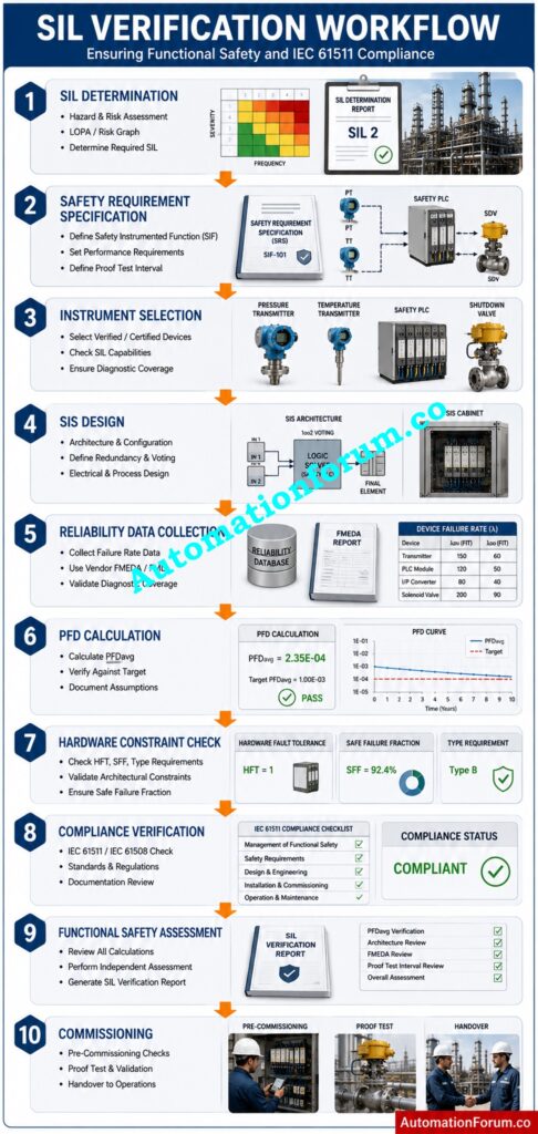
Typical Contents of a SIL Verification Report
A professional SIL Verification Report contains both project information and detailed engineering calculations. Each section supports the verification process and enables traceability throughout the safety life-cycle.
Typical Contents of a SIL Verification Report Table
| Section | Description |
| Project Information | Project name, plant unit, document number, revision, and responsible engineers |
| Applicable Standards | IEC 61511, IEC 61508, company engineering standards, and project specifications |
| Safety Instrumented Function Details | Description and identification number for each Safety Instrumented Function |
| Process Hazard | Hazard being prevented by the safety function |
| Cause | Events that initiate the hazardous condition |
| Consequence | Expected impact if the safety function fails |
| Required SIL | Target Safety Integrity Level from SIL Determination |
| Operating Mode | Low demand, high demand, or continuous mode |
| Demand Rate | Estimated frequency of safety demands |
| Process Safety Time | Maximum allowable response time before hazardous consequences occur |
| Trip Set Point | Instrument trip value initiating the shutdown |
| Architecture Description | Overall configuration of the complete safety loop |
| Sensor | Instrument type, redundancy, certification, and diagnostics |
| Logic Solver | Safety PLC or safety relay information |
| Final Element | Shutdown valve or other final control device details |
| Voting Architecture | Configurations such as 1oo1, 1oo2, or 2oo3 |
| Equipment Information | Manufacturer, model, certification, and hardware details |
| Failure Data | Reliability values obtained from FMEDA reports or approved databases |
| Proof Test Information | Proof test interval, coverage, and procedures |
| Engineering Assumptions | Operating conditions, repair times, and maintenance assumptions |
| SIL Verification Calculations | Results for PFD Average, hardware constraints, and overall SIL achievement |
| Compliance Check | Verification against IEC requirements |
| Recommendations | Suggested improvements where necessary |
| Engineering Conclusion | Final statement confirming compliance or identifying required actions |
Each section provides some of the engineering basis that the safety function shall reliably perform its intended service life. Together, these sections create a complete compliance report that supports design reviews, commissioning activities, and future plant audits.
Safety Instrumented Function Verification Example
Reactor High High Pressure Trip Example
Consider a High High Reactor Pressure Trip designed to prevent reactor overpressure.
The SIL Determination study specifies Required SIL Two. The safety function consists of a pressure transmitter connected to a Safety PLC. The logic solver activates a safety relay that de energizes a shutdown valve, isolating the reactor feed.
Master Functional Safety Concepts Every Automation Professional Should Know: Process Safety vs Functional Safety: Key Differences, SIS, SIF, SIL & IEC 61511 Guide
Step by Step SIF Verification Process
During SIL Verification, engineers first collect certified failure data for every device. Sensor diagnostics, safety PLC architecture, shutdown valve reliability, proof test intervals, maintenance assumptions and operating demand rate are assessed.
Then the whole safety loop is tested with certified SIL verification software. The PFD Average is calculated and compared with the permissible limits for SIL Two. Hardware fault tolerance, safe failure fraction and diagnostic coverage are also validated against IEC criteria.
SIL Verification Results
If all requirements are met, the Safety Instrumented Function is verified as meeting the requirements. If not, engineers may recommend shorter proof test intervals, improved diagnostics, redundant transmitters, or higher reliability final elements until compliance is achieved.
Learn Critical Shutdown Strategies That Prevent Major Process Incidents: ESD vs PSD: Difference Between Emergency Shutdown System and Process Shutdown System
SIF Verification Example Table
| Item | Description |
| SIF Information | High High Reactor Pressure Trip |
| Required SIL | SIL Two |
| Operating Mode | Low demand |
| Trip Action | Close shutdown valve and isolate reactor feed |
| Architecture | Pressure transmitter, Safety PLC, safety relay, shutdown valve |
| Expected Result | Verified compliance with SIL Two requirements before commissioning |
Verify Every Safety Requirement Before Audits With Complete Confidence: Advanced Safety Instrumented System (SIS) Inspection Checklist for IEC 61511 Compliance
SIL Verification Calculations Explained
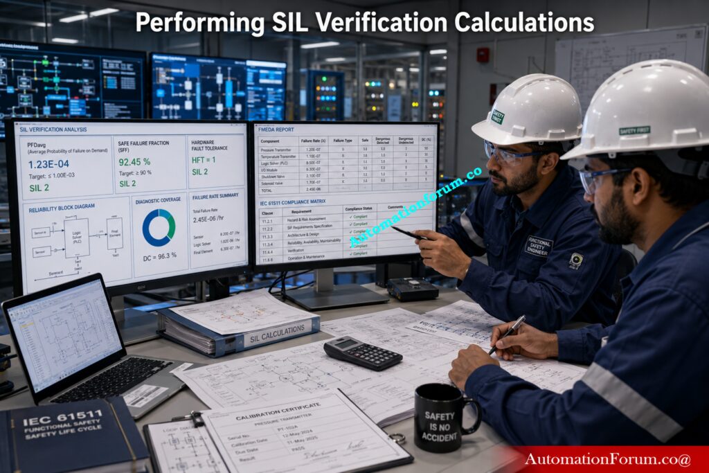
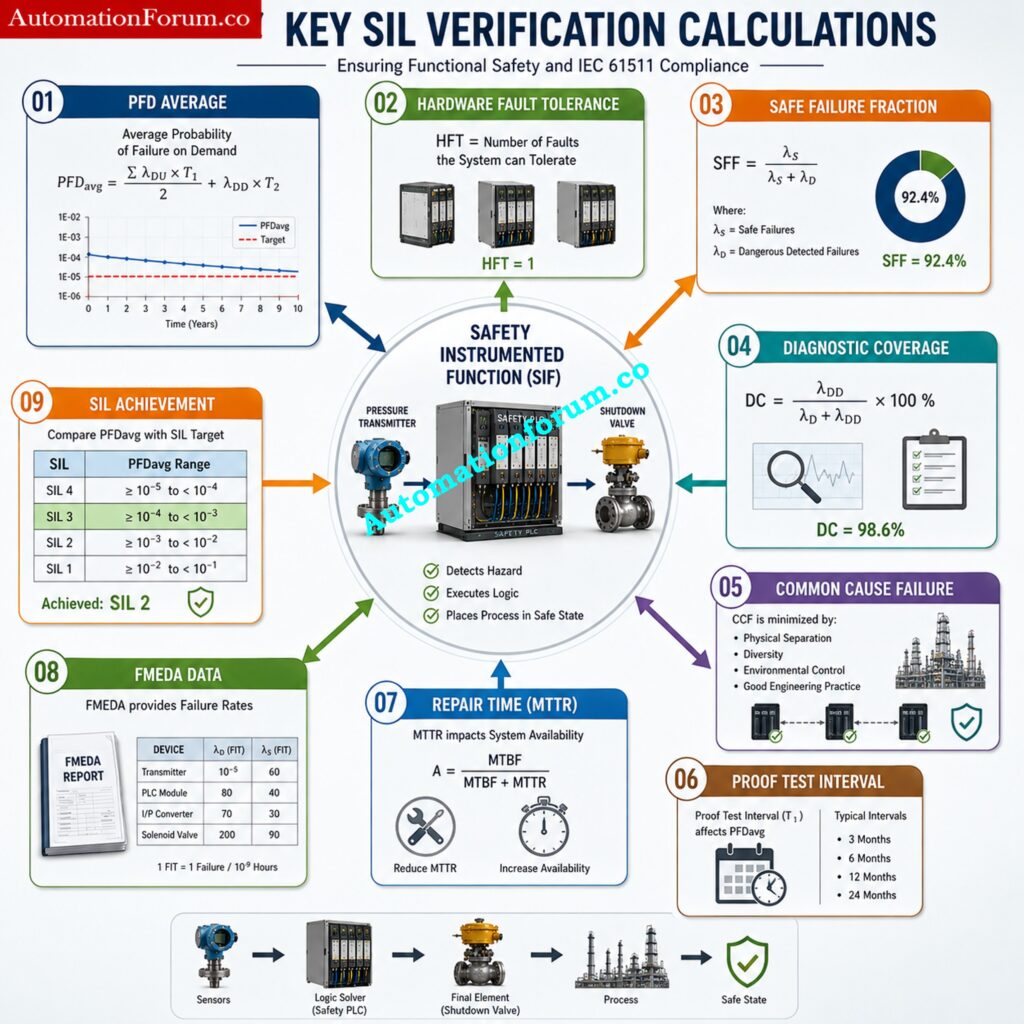
- SIL Verification calculations evaluate whether the complete Safety Instrumented Function can achieve the required level of risk reduction during plant operation.
- The most important parameter is Probability of Failure on Demand Average, commonly called PFD Average. It represents the likelihood that the safety function will fail when required.
- Hardware Fault Tolerance measures the system’s capacity to continue proper operation following hardware faults.
- The Safe Failure Fraction (SFF) is the proportion of failures that are either safe or self-detecting (before they become dangerous).
- Common Cause Failures are failures that might impact redundant equipment at the same time due to common environmental conditions, maintenance faults or design deficiencies.
- The Diagnostic Coverage defines the effectiveness of the built in diagnostics to detect dangerous failures before they prevent proper operation.
- The Proof Test Interval has a substantial impact on the reliability of the system because undiscovered problems are not detected until the testing is completed.
- The Repair Time also affects overall reliability. Quicker repair means safety functions are restored faster, and there is less overall risk exposure.
- Partial stroke testing is an excellent way to enhance fault identification on several shutdown valves without shutting down the entire process.
These evaluations are usually done by engineers using tools like exSILentia, SILcet, GRIF, Reliability Workbench, and Isograph Reliability. These tools make difficult reliability tests easier, and help ensure computations are consistent with standard engineering procedures. The last results decide if the Safety Instrumented Function is effectively meeting the intended SIL.
Improve System Reliability Using Proven Redundancy Engineering Techniques: Redundant Transmitters Explained: Reliability, Voting Logic and SIL for Instrumentation Engineers
Engineering Inputs and Outputs for SIL Verification
Successful SIL Verification requires correct engineering information acquired over the project lifecycle.
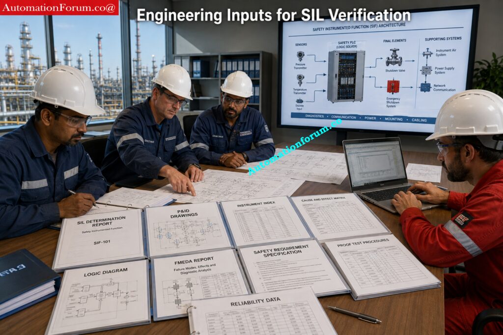
Engineering Inputs for SIL Verification
| Input Document | Purpose |
| SIL Determination Report | Defines required SIL |
| Safety Requirement Specification | Specifies functional requirements |
| Cause and Effect Matrix | Defines shutdown logic |
| P and ID | Identifies process connections |
| Instrument Index | Lists field instruments |
| FMEDA Reports | Provides failure data |
| Safety Manual | Defines equipment limitations |
| Logic Diagrams | Shows control logic |
| Proof Test Procedures | Defines testing methods |
| Reliability Data | Supports verification calculations |
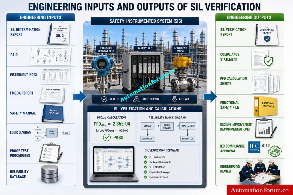
Engineering Outputs for SIL Verification
| Output Document | Purpose |
| SIL Verification Report | Demonstrates SIL compliance |
| PFD Calculation Sheets | Documents calculation results |
| Compliance Statement | Confirms IEC compliance |
| Functional Safety File | Maintains lifecycle documentation |
| Recommendations for Design Improvements | Identifies required corrective actions |
Stop Confusing Shutdown Systems With This Practical Engineering Explanation: ESD vs SIS Difference When to Use Each and Practical Engineering Guide
Best Engineering Practices for SIL Verification
Successful SIL Verification requires correct engineering information acquired over the project lifecycle.
- Use equipment approved for functional safety purposes whenever possible.
- Calculations must be based on real data of reliability derived from approved FMEDA reports and manufacturers safety guides.
- Schedule proof testing at appropriate intervals and decrease repair times to preserve system integrity. Add as much diagnostic coverage as is reasonable to find dangerous failures early.
- Update all backup documentation and verify each engineering assumption prior to finalizing calculations.
- Independent validation of each Safety Instrumented Function against system level assumptions.
- Review all verification data throughout design reviews Update documentation after plant adjustments Final engineering review prior to commissioning
These practices enhance the confidence that all safety functions will continue to execute as intended throughout the safety lifetime.
Build Strong Functional Safety Knowledge With This Complete Expert Guide: What is SIS, SIF and SIL? An In-Depth Guide to Functional Safety in Process Industries
Common Challenges During SIL Verification
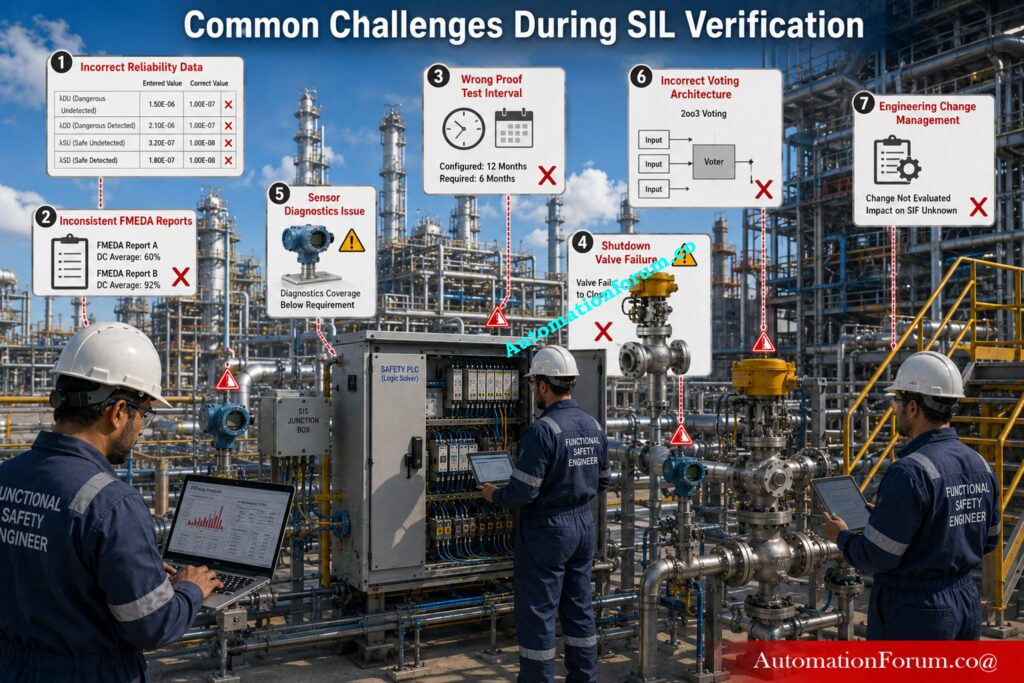
Although SIL Verification is based on a systematic engineering procedure, there are various practical obstacles that can alter the correctness of the final conclusions. The early detection and correction of these errors enables engineers to provide a reliable and compliant SIL Verification Report.
Inconsistent Reliability Data
One prevalent problem is the use of inconsistent reliability data. Failure rates collected from different sources, manufacturer papers, or obsolete FMEDA reports may not be consistent. Engineers must always use approved and validated reliability data that is consistent with the project requirements.
Incorrect Engineering Assumptions
Another pitfall is to make wrong engineering assumptions. If repair times, proof test intervals or demand rates are not realistic the findings of the verification will be misleading. Each assumption should be discussed with operations, maintenance and process safety teams to verify it reflects actual plant circumstances.
Equipment Selection Issues
Selection of improper equipment can also hinder a Safety Instrumented Function from achieving its goal SIL. Systems that do not have adequate diagnostic capabilities or functional safety certification may require further redundancy or more regular proof testing.
Accurately Verify Safety Performance Before Commissioning Any Critical Loop: SIF PFDavg / SIL Verification – Complete Guide + Online Calculator (IEC 61508 / 61511)
Complex Voting Architectures
Complex voting architectures present another difficulty. Configurations such as one-out-of-two or two-out-of-three increase fault tolerance, but require careful consideration of common cause failures and maintenance procedures. If these structures are modelled incorrectly the computed PFD Average can be considerably affected.
Engineering Changes During Projects
Another common concern is engineering changes during project execution. Changes to instrument replacements, logic or process design can render existing verification results obsolete. Therefore, the SIL Verification Report should always be updated whenever significant modifications are made to the Safety Instrumented System.
Learn The Engineering Logic Behind Reliable Dual Solenoid Operation: Understanding 2 out of 2 SOV: Working & Configuration
Independent Technical Review
Finally, independent technical review plays an important role in improving report quality. Detailed assessment of calculation mistakes, missing assumptions, documentation gaps and non-compliance issues is carried out by expert functional safety engineers before commissioning starts.
By systematically solving these issues, engineering teams can provide a more accurate Safety Integrity Level Verification Report and gain more confidence that each Safety Instrumented Function will work as intended throughout the plant lifecycle.
Reduce Operational Risk By Following Proven Testing And Repair Practices: Testing and Repair Deferral – IEC Guidelines, Procedure, and Best Practices
Benefits of a SIL Verification Report
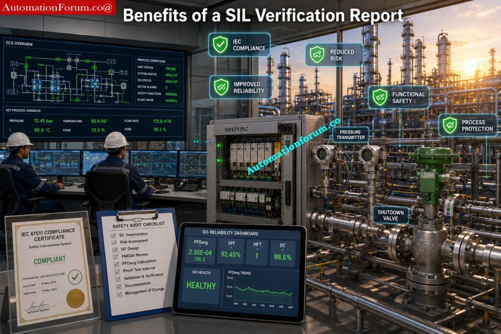
A carefully designed SIL Verification Report offers considerable benefits throughout the Functional Safety Lifecycle. It demonstrates conformity with international standards and improves the dependability, availability and safety of every Safety Instrumented Function. The report provides essential engineering evidence for use during design reviews, commissioning, audits and future plant modifications.
Improves Process Safety
A SIL Verification Report certifies that all Safety Instrumented Functions may reduce process risk to an acceptable level. This helps to avoid hazardous situations, protect personnel, minimise environmental effect and maintain essential plant assets.
Download Essential Functional Safety Terms Every Engineer Should Know: Functional Safety Terminology – Excel Download for Industrial Automation
Demonstrates IEC 61511 and IEC 61508 Compliance
The report offers recorded evidence that the Safety Instrumented System has been assessed against the criteria of IEC 61511 and IEC 61508. This paperwork is also required for Functional Safety Assessments, regulatory inspections and project audits.
Prepare For Technical Interviews With Industry Focused Functional Safety Questions: Safety Instrumented System(SIS) Interview Questions and Answers
Reduces Operational Risk
The report verifies the Probability of Failure on Demand, Hardware Fault Tolerance and Safe Failure Fraction to guarantee that safety functions may be relied upon to operate when needed. This greatly minimizes the probability of dangerous equipment failures.
Supports Functional Safety Assessment
One of the main technical deliverables that are assessed in a Functional Safety Assessment is the SIL Verification Report. It gives unequivocal evidence that the Safety Instrumented Functions installed are meeting the specified Safety Integrity Level and project safety objectives.
Improves SIS Engineering Documentation
The report brings together into one document the reliability estimates, engineering assumptions, proof test information, equipment data and compliance records. This allows for better traceability of documents, facilitates future revisions and helps with maintenance during the lifecycle of the Safety Instrumented System.
Discover Critical Shutdown Signals That Protect High Risk Industrial Plants: Signals for Emergency Valve Shutdown in Critical Processes
Frequently Asked Questions (FAQs) About SIL Verification Report
What is a SIL Verification Report?
A SIL Verification Report is an engineering document that verifies that a Safety Instrumented Function has achieved its required Safety Integrity Level utilizing reliability calculations and IEC compliance checks. It confirms the full Safety Instrumented System can execute its safety function as intended.
Challenge Your Safety Knowledge With Expert Level Engineering Questions: Top 25 MCQs on Safety Integrity Level (SIL) for Instrumentation and Control Engineers
What is a SIL Report?
A SIL Report is a generic term and may refer to a SIL Determination Report, a SIL Verification Report or a SIL Validation Report. The type of report depends on the stage in the Functional Safety Lifecycle.
What is the Difference Between SIL Assessment and SIL Verification?
SIL Assessment determines the required Safety Integrity Level based on hazard and risk analysis. SIL Verification confirms that the detailed Safety Instrumented System design actually meets that required SIL.
How Do You Perform a SIL Assessment?
A SIL Assessment is performed using risk analysis techniques such as LOPA, Risk Graph, or Risk Matrix. It defines the level of risk reduction needed for each Safety Instrumented Function.
How is SIL Calculated?
The SIL is validated by assessing many metrics including Probability of Failure on Demand Average (PFDavg), Hardware Fault Tolerance, Safe Failure Fraction, diagnostic coverage, proof test interval and equipment reliability statistics.
Who Issues SIL Certification?
Then, independent certification companies (such as TUV, Exida or FM Approvals) provide SIL certification after analyzing equipment or development processes to IEC 61508 criteria.
When Should a SIL Verification Report Be Prepared?
A SIL Verification Report is typically prepared after detailed engineering and before commissioning. It confirms that the final Safety Instrumented System design complies with the required Safety Integrity Level.
What Software is Used for SIL Verification?
Popular engineering software are exSILentia, SILcet, GRIF, Reliability Workbench and Isograph Reliability. These tools assist to do SIL calculations and generate verification reports.
What Information is Included in a SIL Verification Report?
The typical report will include information of the Safety Instrumented Function, the architecture, reliability statistics, proof test intervals, SIL calculations, compliance checks, engineering assumptions, and the final verification results.
Why is a SIL Verification Report Important?
A SIL Verification Report provides proof of compliance with IEC 61511 and IEC 61508, and confidence in the reliable operation of all Safety Instrumented Functions when a hazardous event occurs.
Challenge Your Functional Safety Skills Before Your Next Major Project: Test Your Expertise in Safety Instrumented Systems (SIS): Knowledge Quiz
Conclusion: Why a SIL Verification Report is Essential for Functional Safety
A SIL Verification Report is far more than a calculation document. It is the engineering evidence that demonstrates every Safety Instrumented Function can achieve its required Safety Integrity Level under actual operating conditions. The study certifies that the entire Safety Instrumented System satisfies the performance standards established during the risk assessment, by analyzing equipment reliability, architecture, diagnostic capacity, proof testing and maintenance assumptions.
Prepared in accordance with IEC 61511 and supported by equipment data developed under IEC 61508, the report provides confidence that safety functions will perform when demanded. It also supports commissioning, Functional Safety Assessment, plant modifications, and long term maintenance planning. Throughout the Functional Safety Lifecycle, the SIL Verification Report remains one of the most valuable engineering deliverables because it demonstrates compliance, strengthens process safety, and helps ensure safe and reliable plant operation.
Refer the below link for the Top Critical Mistakes in Safety Instrumented System Design as per ISA 84 Standard and How to Avoid Them
