
Capacitance Level Sensor Calculator
1Probe & Tank Geometry
mm / m / in2Calibration & Reading
pF✓Result
- Understanding Capacitance Level Measurement
- What Is Capacitance Level Measurement?
- Why Use a Capacitance Level Sensor Calculator?
- Inputs Required for Capacitance Level Calculation
- How to Calculate Level From Measured Capacitance
- What Is Capacitance Span in Level Measurement?
- How to Calculate Capacitance From Probe and Tank Dimensions
- Bare Probe and Insulated Probe in Capacitance Level Measurement
- Theoretical Capacitance for Level Measurement
- Capacitance Level Measurement Sensitivity
- Practical Capacitance Level Measurement Example
- How to Use the Capacitance Level Sensor Calculator
- Common Capacitance Level Calculation Mistakes
- Troubleshooting Unexpected Capacitance Level Readings
- Capacitance Level Sensor Calculator Limitations
- Capacitance Level Sensor Calculator: Key Engineering Takeaways
- Frequently Asked Questions About Capacitance Level Measurement
Understanding Capacitance Level Measurement
Capacitance level measurement is an important technique used in process instrumentation for detecting and measuring liquid level inside vessels, tanks and process equipments. The capacitance level sensor works by sensing a change in electrical capacitance due to a change in the material around the sensing probe.
When the probe is surrounded by vapor, the electrical capacitance has one value. As liquid rises around the probe, the dielectric environment changes and the capacitance changes accordingly. This change can be used by a capacitance level transmitter to determine the level of the process material.
For instrumentation engineers, understanding this relationship is useful during instrument selection, preliminary engineering, calibration review, commissioning and troubleshooting. Engineers may need to calculate theoretical capacitance from probe and tank dimensions or determine liquid level from measured capacitance and known calibration values.
The Capacitance Level Sensor Calculator provides two calculation modes for these applications. The first calculates level from measured capacitance using empty and full calibration values. The second calculates theoretical capacitance from probe geometry, tank or reference diameter, insulation properties and dielectric constants.
The calculator is an engineering aid for understanding capacitance level measurement. Its theoretical results should not replace manufacturer specifications or actual field calibration.
Convert Difficult Capacitance Readings Into Accurate Level Values: Capacitance to Level Conversion Calculator for Level Transmitters
What Is Capacitance Level Measurement?
How Does a Capacitance Level Sensor Work?
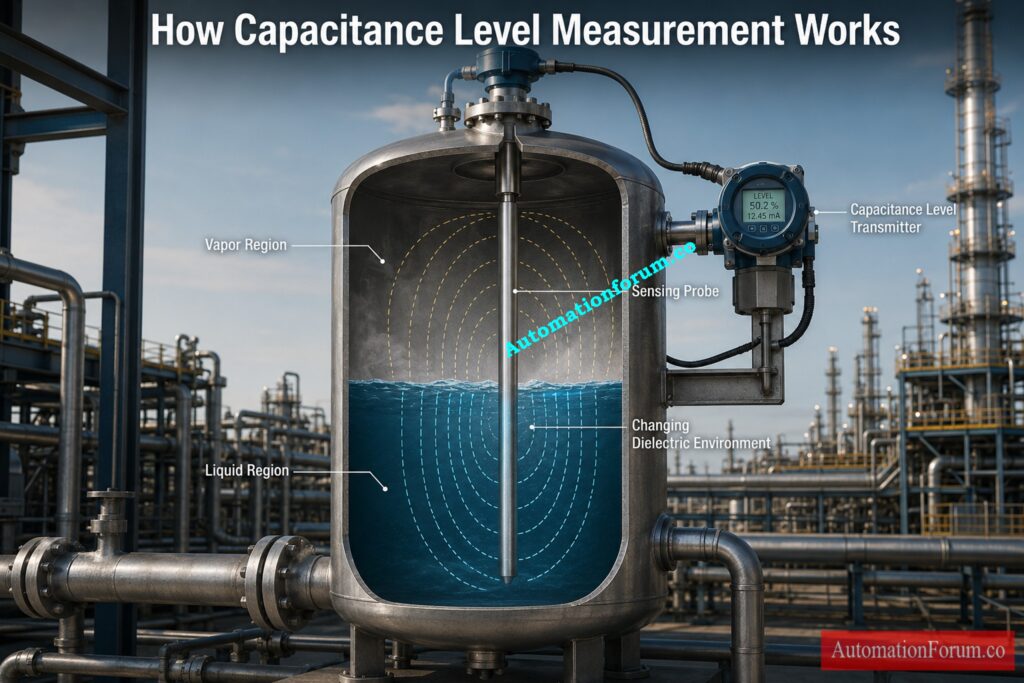
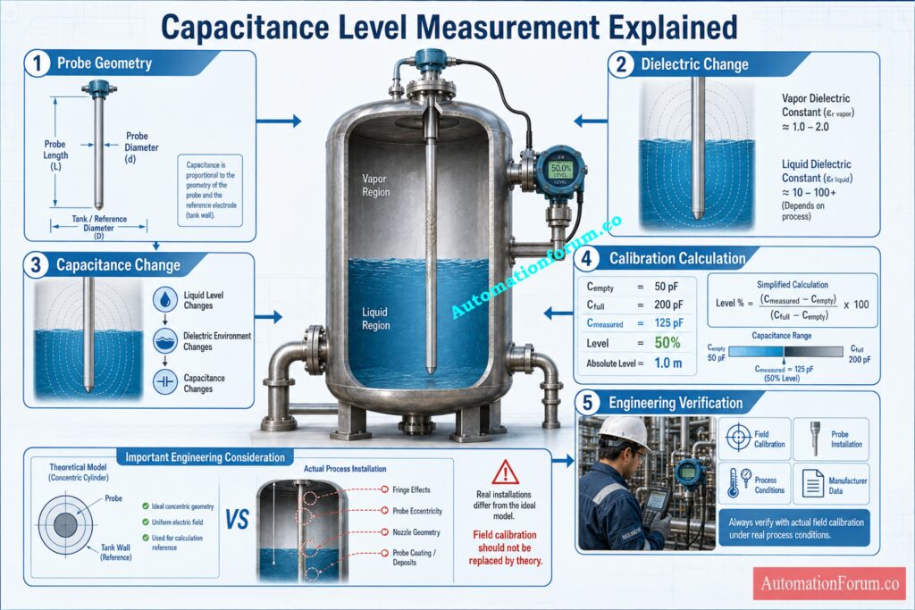
A capacitance level sensor uses the electrical capacitance formed between a sensing probe and a reference electrode or conductive vessel.
Capacitance Probe and Reference Electrode
The capacitance depends on the physical geometry of the sensing arrangement and the dielectric material surrounding the probe. When the process level changes, the proportion of the probe surrounded by vapor and liquid also changes.
Effect of Dielectric Constant on Level Measurement
Consider a vertical probe installed inside a vessel. At an empty condition, the probe is mainly surrounded by vapor. At a full condition, the sensing region is surrounded by liquid. If the dielectric properties of the liquid differ from those of the vapor, the capacitance changes.
This difference forms the basis of capacitance level measurement.
The calculator models the probe and tank as a concentric cylindrical arrangement. It uses probe diameter, tank or reference diameter, probe length and dielectric properties to estimate theoretical capacitance.
For an actual instrument installation, the physical arrangement is more complicated. Probe position, nozzle geometry and other installation effects can influence the actual capacitance.
Master Capacitance Level Transmitter Operation And Field Troubleshooting: Principle, Installation and trouble shooting of capacitance type level transmitter
Why Use a Capacitance Level Sensor Calculator?
Capacitance Level Calculation for Instrumentation
A capacitance level calculation can be useful during several stages of an instrumentation project.
During preliminary engineering, an engineer can estimate theoretical empty and full capacitance from the physical dimensions of the probe and vessel. This helps in understanding the expected measurement behaviour.
During commissioning, the calculated values can be compared with actual instrument calibration data. If a measured capacitance differs significantly from the expected value, the engineer can investigate the installation and process conditions.
The calculator is also useful when reviewing calibration data. If empty capacitance, full capacitance and measured capacitance are known, the corresponding percentage level and absolute level can be calculated.
Applications of Capacitance Level Calculation
Typical applications include:
- Preliminary capacitance level measurement analysis
- Instrument selection support
- Theoretical capacitance calculation
- Calibration data review
- Commissioning calculations
- Understanding capacitance span
- Reviewing unexpected capacitance readings
- Comparing theoretical and actual values
- Understanding the effect of probe geometry
The purpose is not simply to obtain a number. The calculation helps an engineer understand how capacitance changes with process level.
Refer the below link for the 15+ Collection of Level Measurement Calculators for Industrial Instrumentation
Inputs Required for Capacitance Level Calculation
The calculator requires several physical and electrical parameters.
Probe Length
Probe length is the covered sensing length used in the calculation. It is also used to convert calculated percentage level into absolute level.
The calculator accepts metres, feet, centimetres and inches for probe length.
Probe Diameter
Probe diameter represents the diameter of the sensing probe. The calculator converts the entered diameter into metres and uses the resulting probe radius in the theoretical capacitance calculation.
The available units include millimetres, metres, centimetres and inches.
Tank or Reference Diameter
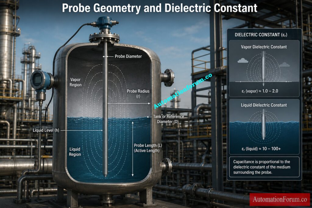
Tank or reference diameter represents the outer reference dimension used by the concentric cylinder model.
The calculator accepts millimetres, metres, centimetres, feet and inches for this input.
Insulation Thickness
Insulation thickness determines whether the calculator treats the probe as bare or insulated.
When insulation thickness is zero, the probe is treated as a bare probe.
When insulation thickness is greater than zero, the calculator treats it as an insulated probe.
Insulation Dielectric Constant
The insulation dielectric constant is used when an insulated probe is selected. The calculator interface provides PTFE as an example with an approximate dielectric constant of 2.1.
The actual value should be based on the insulation material used in the installed probe.
Vapor Dielectric Constant
Vapor dielectric constant represents the dielectric constant of the material surrounding the probe in the vapor region.
The calculator provides air with a value of approximately 1.0 as an example.
Liquid Dielectric Constant
Liquid dielectric constant represents the dielectric constant entered for the process liquid.
The calculator interface provides a value of 2.3 as its example default. The actual process value should be selected according to the application.
Empty Capacitance
Empty capacitance represents the zero percent calibration reference. The calculator identifies it as the 0 percent or LRV reference.
Full Capacitance
Full capacitance represents the 100 percent calibration reference. The calculator identifies it as the 100 percent or URV reference.
Measured Capacitance
Measured capacitance is the capacitance value being evaluated when using the Level from Measured Capacitance mode.
The calibration inputs are expressed in pF.
Eliminate Calibration Errors With Proven Capacitance Techniques: Calibration of capacitance type level transmitter
How to Calculate Level From Measured Capacitance
Capacitance Level Calculation Formula
The first mode calculates liquid level from measured capacitance.
The calculator first computes the calibration span:
Calibration span = Cfull minus Cempty
Then the level percentage is calculated:
Level percentage = (Cmeasured minus Cempty) divided by (Cfull minus Cempty) multiplied by 100
Where:
Cmeasured is the capacitance measured.
Cempty is the empty capacitance corresponding to zero percent.
Cfull is the full capacitance corresponding to 100 percent.
How to Calculate Absolute Liquid Level
The calculator then determines absolute level from probe length:
Absolute level = Level percentage divided by 100 multiplied by Probe length
The result is displayed as a percentage together with the calculated absolute level.
Capacitance Level Calculation Example
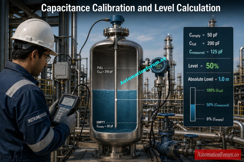
Consider an illustrative installation with:
Probe length = 2 m
Empty capacitance = 50 pF
Full capacitance = 200 pF
Measured capacitance = 125 pF
The calibration span is:
200 minus 50 = 150 pF
The calculated level is:
(125 minus 50) divided by 150 multiplied by 100
The result is 50 percent.
For a 2 m probe:
Absolute level = 50 divided by 100 multiplied by 2
Absolute level = 1 m
This example shows how the calculator interpolates level between the empty and full calibration points.
Solve Critical Capacitance Transmitter Problems Before Failures: Calibration, Troubleshooting and Installation of Capacitance Type Level Transmitter
What Is Capacitance Span in Level Measurement?
How Is Capacitance Span Calculated?
Calibration span is the difference between full capacitance and empty capacitance.
Calibration span = Cfull minus Cempty
The span is the variation in capacitance according to the calibrated measurement range.
For example, the calibration range is 150 pF if the empty capacitance is 50 pF and the full capacitance is 200 pF.
Understanding In Range and Out of Range Results
The measured capacity is then compared to these two reference values.
If the calculated level is between 0 and 100 percent, the calculator displays the result as In range.
If the calculated level falls below 0 percent or above 100 percent, the calculator displays Out of range.
An out of range result should not immediately be considered evidence of transmitter failure. The engineer should verify calibration values, process conditions, probe installation, measurement wiring and instrument configuration.
Verify Hazardous Area Loop Parameters Before Commissioning: Intrinsic Safety Entity Parameter Calculator for Reliable Hazardous Area Loop Design
How to Calculate Capacitance From Probe and Tank Dimensions
Concentric Cylinder Capacitance Calculation
The second calculator mode estimates theoretical capacitance from the probe and tank dimensions.
The calculator uses a concentric cylinder model. The calculation starts with the vacuum permittivity:
ε₀ = 8.854 × 10⁻¹² F/m
The capacitance per unit length for the cylindrical arrangement is calculated using:
C′ = 2πε₀K divided by ln(Rout divided by Rin)
Theoretical Empty and Full Capacitance
For a bare probe, the calculator applies this relationship separately to vapor and liquid conditions.
For vapor:
C′v = 2πε₀Kair divided by ln(Rt divided by Rp)
For liquid:
C′l = 2πε₀Kliquid divided by ln(Rt divided by Rp)
The theoretical capacitance is then obtained by multiplying capacitance per unit length by probe length.
The calculator converts the result to pF for display.
Master Essential Level Instrument Calibration Procedures Faster: Calibration Procedures for Level Measurement Devices
Bare Probe and Insulated Probe in Capacitance Level Measurement
Bare Capacitance Probe Calculation
The calculator automatically determines whether the probe is bare or insulated from the entered insulation thickness.
When insulation thickness is zero, the probe is treated as bare.
When insulation thickness is greater than zero, the calculator creates an insulation radius by adding insulation thickness to the probe radius.
Insulated Capacitance Probe Calculation
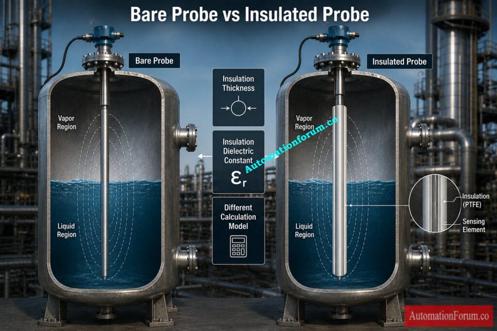
For an insulated probe, the calculation becomes more specific because the insulation layer forms part of the electrical system.
The calculator calculates liquid capacitance per unit length using:
C′l = 2πε₀Kins divided by ln(Rins divided by Rp)
The calculator specifically describes the liquid as conductive and therefore treats the liquid as the outer plate.
Effect of Insulation Dielectric Constant
For vapor, the calculator uses the insulation dielectric constant and vapor dielectric constant together:
C′v = 2πε₀ divided by [(1 divided by Kins) multiplied by ln(Rins divided by Rp) plus (1 divided by Kair) multiplied by ln(Rt divided by Rins)]
This distinction is important. An engineer should not assume that the liquid dielectric constant is directly substituted into the insulated probe liquid formula used by this calculator. The actual implemented calculation uses the insulation dielectric constant for that condition.
Fix Persistent Level Transmitter Problems With Proven Methods: How to Troubleshoot Level Transmitter Problems and Their Solutions
Theoretical Capacitance for Level Measurement
Theoretical Empty Capacitance
When using the dimension based calculation, the calculator reports theoretical empty capacitance and theoretical full capacitance.
The theoretical empty capacitance is calculated from the vapor capacitance per unit length multiplied by probe length.
The theoretical full capacitance is calculated from the liquid capacitance per unit length multiplied by probe length.
Theoretical Full Capacitance
The calculator then determines theoretical capacitance span:
Theoretical span = Cfull minus Cempty
These values provide useful information about the expected electrical measurement range.
However, theoretical capacitance should not automatically be used as the actual calibration values of an installed transmitter.
The model assumes a simplified concentric cylindrical arrangement. Real installations can include probe eccentricity, nozzle geometry and fringe effects that are not represented by this calculation.
Eliminate False Echoes And Restore Reliable Radar Measurement: Radar Level Transmitter False Echo Troubleshooting Guide: Causes, Symptoms, Echo Curve Analysis and Fixes
Capacitance Level Measurement Sensitivity
How Is Capacitance Sensitivity Calculated?
The calculator also provides sensitivity when operating in the Capacitance from Dimensions mode.
Sensitivity is calculated as:
Sensitivity = Capacitance span divided by Probe length
The displayed unit is pF/m.
This value indicates the theoretical capacitance change associated with one metre of probe length based on the calculated capacitance span.
Understanding Capacitance Sensitivity in pF/m
For example, if the calculated capacitance span is 150 pF and the probe length is 2 m:
Sensitivity = 150 divided by 2
Sensitivity = 75 pF/m
This provides a useful way to understand how the theoretical capacitance changes over the sensing length.
It should not, however, be interpreted as the complete performance specification of a commercial capacitance level transmitter. Actual instrument performance depends on the complete sensing system and application.
Calculate Open Tank Zero Suppression Without Measurement Errors: DP Calculator for Zero Suppression in Open Tank Level Measurement
Practical Capacitance Level Measurement Example
Consider a vertical process vessel with a capacitance probe installed for liquid level measurement.
- The instrumentation engineer first collects the probe length, probe diameter and vessel reference diameter from the instrument and mechanical documentation.
- The engineer then determines whether the probe is bare or insulated. If insulation is present, the insulation thickness and dielectric constant must be entered.
- The next step is to enter the vapor and liquid dielectric constants required by the calculator.
- If actual calibration data is available, the engineer can use the Level from Measured Capacitance mode. Empty capacitance, full capacitance and measured capacitance are entered.
- The calculator determines the calibration span and interpolates the measured capacitance between the empty and full conditions.
- The engineer can then check the percentage level and the absolute level calculated.
- The theoretical empty and full capacitance values are also relevant for comparison.
- If theoretical values are significantly different from actual calibration data, the engineer should investigate the physical installation rather than automatically changing the calibration.
Test Your GWR Commissioning Skills With Advanced Questions: Advanced Guided Wave Radar Level Transmitter Commissioning Quiz for Process Industries
How to Use the Capacitance Level Sensor Calculator
Step 1: Select the Calculation Mode
Choose Level from Measured Capacitance when empty, full and measured capacitance values are available.
Choose Capacitance from Dimensions when you want to calculate theoretical capacitance from probe and tank dimensions.
Step 2: Enter Probe Length
Enter the length of the active probe, and choose the proper unit. Probe length is used to calculate absolute level and theoretical capacitance.
Step 3: Enter Probe Diameter
Input the probe diameter and select the relevant unit. This value is utilized to establish the probe geometry for the theoretical capacitance calculation.
Step 4: Enter Tank or Reference Diameter
Enter the tank or reference diameter used in the concentric cylinder calculation model.
Step 5: Enter Insulation Thickness
Enter probe insulation thickness. Use zero for a bare probe. A value greater than zero causes the calculator to treat the probe as insulated.
Step 6: Enter Dielectric Constants
Enter the insulation dielectric constant (if applicable)Enter the vapor dielectric constantEnter the liquid dielectric constant Use values according to the actual probe material and technique.
Step 7: Enter Empty and Full Capacitance
For level calculation, enter empty and full capacitance. These are the 0 percent and 100 percent calibration reference points.
Step 8: Enter Measured Capacitance
Measured capacitance (pF) . This value is used by the calculator with the empty and full capacitance to determine the calculated level.
Step 9: Review Calculated Level
Verify computed level percentage, absolute level and calibration span. The calculator also tells if the determined level is in the 0 to 100 percent range.
Step 10: Review Theoretical Capacitance and Sensitivity
If utilizing the dimension based method, verify the estimated theoretical empty capacitance, full capacitance, calibration span and sensitivity.
Step 11: Verify the Results
Compare the predicted values with real instrument calibration data and manufacturer information. The theoretical calculation should be treated as an engineering reference because actual installation effects can influence capacitance measurement.
Troubleshoot Closed Tank DP Level Problems Step By Step: Step-by-Step Troubleshooting Checklist for Closed Tank DP Type Level Transmitter
Common Capacitance Level Calculation Mistakes
- Using the Wrong Dielectric Constant: The dielectric constant has a direct influence on theoretical capacitance. An incorrect value can produce a misleading calculation.
- Entering Incorrect Dimensions: Probe diameter, probe length and tank or reference diameter should represent the actual installation.
- Selecting the Wrong Unit: The calculator automatically converts dimensional inputs into metres. Incorrect unit selection can therefore produce a major calculation error.
- Ignoring Probe Insulation: A probe with insulation should not be calculated as a bare probe. Insulation thickness determines which calculation path is used.
- Treating Theoretical Values as Field Calibration Values: Theoretical capacitance provides an estimate based on the model. It should not automatically replace actual empty and full calibration values.
- Using Incorrect Calibration References: Incorrect empty or full capacitance will directly affect the calculated level.
- Ignoring Installation Geometry: The concentric cylinder model does not represent every physical installation.
- Ignoring Process Changes: Changes in process material properties can influence capacitance measurement.
- Skipping Field Calibration A theoretical calculation is useful, but actual instrument calibration remains necessary for a real process installation.
Calculate Displacer Calibration Values With Greater Confidence: Displacer Level Transmitter Calibration Calculator for Dry Calibration Step by Step Guide
Troubleshooting Unexpected Capacitance Level Readings
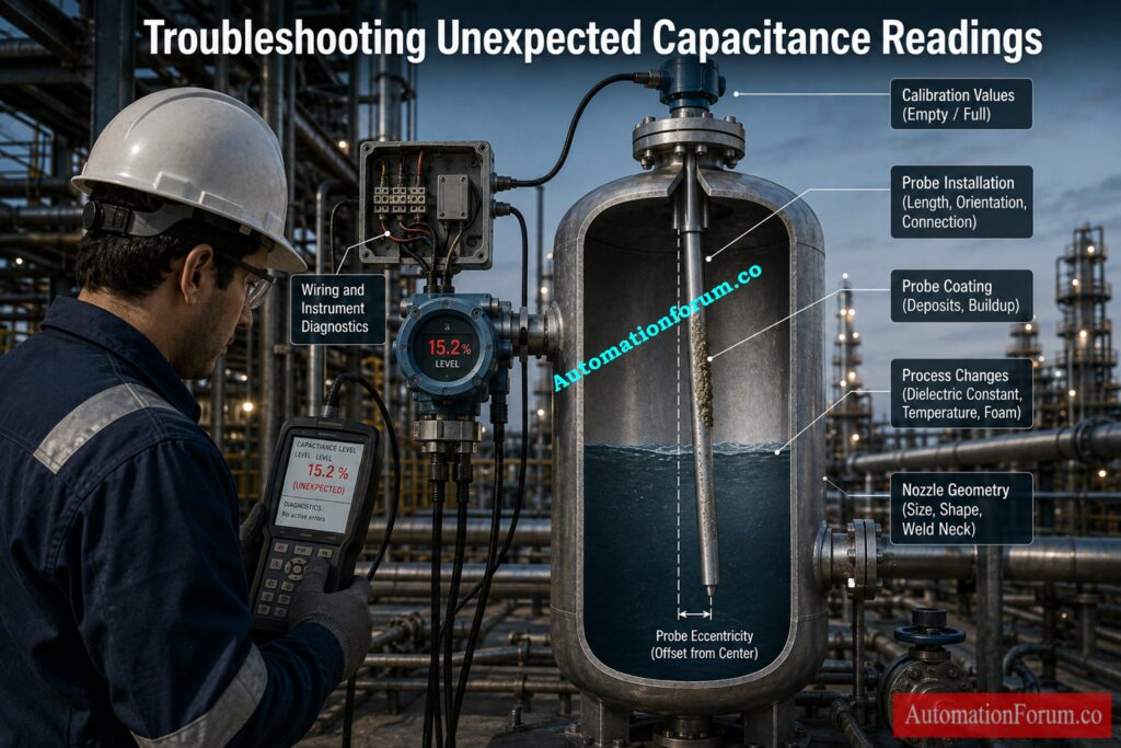
- If the measured capacitance produces an unexpected level, begin with the calibration information.
- Verify Cempty, Cfull and Cmeasured. Confirm that the values are expressed in the same units and that the empty and full references correspond to the actual instrument calibration.
- Next, verify the physical probe dimensions and insulation condition.
- If the theoretical calculation differs considerably from the actual measurement, examine the installation arrangement. Probe eccentricity, nozzle geometry and fringe effects can contribute to differences between the simplified calculation and the physical installation.
- Process conditions should also be considered. Changes in the process material can change its dielectric behaviour.
- Probe coating or deposits may also influence the actual measurement.
- The calculator can help an engineer compare theoretical values and calibration relationships. It cannot determine whether the transmitter electronics, wiring or probe hardware has failed. Those conditions require physical inspection, instrument diagnostics and appropriate manufacturer information.
Master Dry Displacer Calibration Using Weight Loss Calculations: Dry Calibration of Displacer Level Troll Using Weight Loss Calculator
Capacitance Level Sensor Calculator Limitations
- The Capacitance Level Sensor Calculator uses a theoretical concentric cylinder model for its dimension based calculation.
- Real process installations can differ from this ideal geometry. The calculator itself identifies fringe effects, probe eccentricity and nozzle geometry as effects that are not captured by the model.
- This means that theoretical empty and full capacitance values may differ from actual field measurements.
- The calculator should therefore be used for engineering understanding, preliminary calculation and comparison rather than as a substitute for application verification.
- For an installed capacitance level transmitter, engineers should perform appropriate two point field calibration and verify the application against the instrument manufacturer’s specifications.
- The actual process conditions, probe construction and installation arrangement must always be considered before accepting a calculated value for operational use.
Test Advanced Drum Level Control Knowledge With Challenging Questions: Three Element Drum Level Control System – Advanced Quiz for Instrumentation Engineers
Capacitance Level Sensor Calculator: Key Engineering Takeaways
Capacitance level measurement depends on the relationship between probe geometry, dielectric properties and the electrical environment surrounding the probe.
The Capacitance Level Sensor Calculator provides two useful calculation approaches. The first calculates liquid level from measured capacitance using empty and full calibration references. The second estimates theoretical capacitance from probe dimensions, tank or reference diameter and dielectric properties.
For instrumentation engineers, the most useful aspect is not simply the calculated number. The calculation provides a way to understand the expected capacitance range, calibration span and theoretical sensitivity of a capacitance level measurement system.
The distinction between bare and insulated probes is particularly important because the calculator applies different equations depending on insulation thickness.
The results should always be interpreted in the context of the actual installation. Theoretical concentric cylinder calculations cannot fully represent fringe effects, probe eccentricity or nozzle geometry.
Used correctly, the calculator can support preliminary engineering, calibration review, commissioning and troubleshooting. Final instrument calibration and application suitability should remain based on actual field conditions and the manufacturer’s technical requirements.
Improve Radar Level Performance With Critical Engineering Checks: Checklist for Best Radar Level Measurement & Control System Performance
Frequently Asked Questions About Capacitance Level Measurement
What is a capacitance level sensor?
Capacitance level sensors sense the level of a liquid by measuring changes in the electrical capacitance between a sensing probe and a reference electrode or the wall of the vessel. The dielectric environment around the probe changes, and so does the capacitance.
How does a capacitance level sensor work?
How do you calculate level from measured capacitance?
The level can be determined by interpolating the recorded capacitance between the empty and full capacitance values:
Level % = (Cmeasured − Cempty) / (Cfull − Cempty) × 100
This is the same calculation as used by the Capacitance Level Sensor Calculator.
What is capacitance span in level measurement?
Capacitance span is the difference between full capacitance and empty capacitance.
Capacitance span = Cfull − Cempty
It represents the capacitance change corresponding to the calibrated measurement range.
Why is dielectric constant important in capacitance level measurement?
The dielectric constant affects the capacitance produced by the sensing arrangement. A difference between the dielectric properties of the vapor and process liquid allows the level change to be detected. Changes in process dielectric properties can also affect measurement behaviour.
What is the difference between a bare and insulated capacitance probe?
A bare probe is directly exposed to the surrounding process material. An insulated probe has an insulating layer around the sensing element. The insulation thickness and dielectric constant affect the theoretical capacitance calculation.
What is the capacitance level sensor calculation formula?
For the level interpolation mode, the calculator uses:
Level % = (Cmeasured − Cempty) / (Cfull − Cempty) × 100
For the dimension based mode, the calculator uses a concentric cylinder capacitance model based on probe radius, reference radius, dielectric constant and vacuum permittivity.
Why is my calculated capacitance different from the actual measured capacitance?
The theoretical calculation uses a simplified concentric cylinder model. Actual installations can be affected by factors such as fringe effects, probe eccentricity and nozzle geometry. Therefore, theoretical and measured capacitance values may differ.
How is a capacitance level transmitter calibrated?
Capacitance level measurement normally requires establishing appropriate empty and full reference conditions for the installed application. The calculated values should be checked against actual field calibration and manufacturer requirements rather than relying only on theoretical capacitance.
What does an out of range capacitance level result mean?
An out of range result means the calculated level is below 0 percent or above 100 percent based on the entered empty and full capacitance values. Check the calibration values, measured capacitance, probe installation and process conditions before concluding that the instrument has a fault.
How is capacitance sensitivity calculated?
The calculator determines theoretical sensitivity by dividing capacitance span by probe length:
Sensitivity = Capacitance span / Probe length
The result is expressed in pF/m and represents the theoretical capacitance change associated with probe length.
Refer the below link for the Hybrid Level Measurement: Capacitance + Guided Wave Radar (GWR) Technology
