- Radar Level Transmitter False Echo Troubleshooting Introduction
- What Is a Radar Level Transmitter?
- Why Radar Level Measurement Is Preferred Over Ultrasonic Systems
- How Radar Level Transmitters Detect Level
- Echo Strength, Threshold and Echo Discrimination
- What Is a False Echo in a Radar Level Transmitter?
- Difference Between Actual Echo and False Echo
- Radar Level Measurement Problems Caused by False Echoes
- Top Causes of False Echo in Radar Level Transmitters
- How to Read Radar Echo Curve Diagnostics
- Step-by-Step Radar Level Transmitter False Echo Troubleshooting
- How to Perform Radar False Echo Mapping
- Guided Wave Radar False Echo Troubleshooting
- Non Contact Radar False Echo Troubleshooting
- Real Plant Case Studies of Radar False Echo Problems
- Radar Level Transmitter False Echo Troubleshooting Checklist
- Best Practices to Prevent False Echo in Radar Level Transmitters
- Frequently Asked Questions on Radar Level Transmitter False Echo Troubleshooting
- Conclusion: Key Takeaways for Reliable Radar Level Measurement
Radar Level Transmitter False Echo Troubleshooting Introduction
Why False Echo Problems Matter in Industrial Level Measurement
Radar level transmitters are now standard instruments in many industrial plants because they give continuous level measurement with strong reliability in difficult process conditions. They are widely used in oil and gas, petrochemical, power generation, water treatment, pharmaceuticals, chemical processing, tank farms, storage terminals, and utility systems.
Where Radar Level Transmitters Are Used in Process Plants
The main reason radar is preferred is simple. It does not depend on direct contact with the product surface in the same way a displacer or float system does, and it is less affected by vapour, pressure, temperature changes, and many process disturbances than older measurement methods. In a clean and stable tank, radar works extremely well. In a real plant, however, the signal can reflect from many other surfaces inside the vessel. That is where false echoes begin.
What This Troubleshooting Guide Will Help You Solve
A false echo is an unwanted reflected signal that the transmitter may wrongly interpret as the actual liquid or solid surface. This can create radar level measurement problems such as unstable reading, sudden jumps, frozen output, false high alarms, false low alarms, poor inventory accuracy, and operator confusion. In some cases, a false echo can even lead to process upset or unnecessary shutdown.
This article explains radar level transmitter false echo troubleshooting in practical field language. It covers what false echoes are, how radar detects level, how to read the echo curve, the most common root causes, how to perform false echo suppression, and how to troubleshoot both non contact radar and guided wave radar in real plant conditions.
Think Your Radar Skills Are Advanced? Prove It Here: Advanced Guided Wave Radar Level Transmitter Commissioning Quiz for Process Industries
What Is a Radar Level Transmitter?
Radar Level Transmitter Working Principle
A radar level transmitter is a level measuring instrument that sends microwave energy toward the product surface and measures the time taken for the reflected signal to return. From that travel time, the transmitter calculates the distance to the surface and converts it into level.
The instrument can be used on tanks, silos, reactors, separators, surge vessels, open channels, and storage systems. It is popular because it gives continuous measurement and can support both control and inventory applications.
Non Contact Radar Level Transmitter vs Guided Wave Radar
There are two major types of radar level measurement.
- Non contact radar measures level without touching the product. It is mounted above the process and sends the signal through the tank space.
- Guided wave radar sends the signal along a probe or cable that is in contact with the product environment.
Both technologies can be very effective, but both can also suffer from false echoes when the installation, process condition, or configuration is not correct.
Boost Measurement Reliability With These Proven Optimization Secrets: Checklist for Best Radar Level Measurement & Control System Performance
Why Radar Level Measurement Is Preferred Over Ultrasonic Systems
Radar is often selected over ultrasonic measurement because it performs better in many difficult process environments. Ultrasonic devices depend on sound waves, so their performance can reduce in vapour, temperature changes, pressure changes, dust, and strong turbulence.
Radar has many advantages because of its usage of microwave energy:
- less influenced by the process gases and vapour
- Improved performance in service at high temperature and pressure
- It works better on many problematic tank geometries than ultrasonic systems
- It offers extensive diagnostics and analysis of the echo curve
- It is more suitable for crucial process control applications.
To summarize, radar is often the method of choice for challenging industrial tanks, but it still requires right installation and adequate configuration.
How Radar Level Transmitters Detect Level
Time of Flight Principle in Radar Level Measurement
Radar level transmitters work on the basis of time of flight. The transmitter sends a signal toward the surface, the signal reflects back, and the transmitter measures the travel time. Since the speed of the signal is known, the instrument can calculate distance and then level.
Signal Reflection and Distance Calculation
The basic sequence is as follows.
- The transmitter emits a microwave signal
- The signal travels through air or vapour space inside the vessel
- The signal reflects from the product surface
- The echo returns to the transmitter
- The electronics measure the travel time
- The instrument calculates the surface distance
- Level is derived from the vessel geometry
Why Echo Strength and Peak Location Matter
The transmitter does not simply look for any echo. It evaluates echo strength, signal quality, peak stability, and location. This is why radar echo curve analysis is so important during troubleshooting.
Refer the below link for the Hybrid Level Measurement: Capacitance + Guided Wave Radar (GWR) Technology
Echo Strength, Threshold and Echo Discrimination
The surface echo must be strong enough to stand out from other reflections. The transmitter uses a signal threshold to decide which echoes to accept. If a false reflection is stronger than the true surface echo, or if the surface echo becomes weak, the transmitter may choose the wrong signal.
This process is called echo discrimination. A good installation makes discrimination easy. A poor installation creates many reflections and makes the decision difficult.
Challenge Your Expertise With This Advanced Engineering Assessment: Advanced Quiz on RADAR Level Measurement for Process Instrumentation Engineers
What Is a False Echo in a Radar Level Transmitter?
Definition of False Echo in Radar Level Measurement
A false echo is a reflected radar signal that does not come from the actual product surface but still appears strong enough to confuse the transmitter.
How False Echoes Mislead the Transmitter
For example, the signal may reflect from:
- A tank wall
- A roof beam
- A ladder
- An agitator
- A heating coil
- A nozzle
- A support structure
- A buildup layer
- A dip pipe
- A splash zone
If the transmitter locks onto that reflection instead of the true surface, the displayed level becomes wrong.
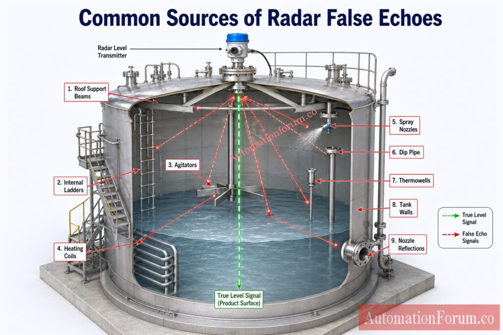
Common Sources of False Radar Echoes in Tanks and Vessels
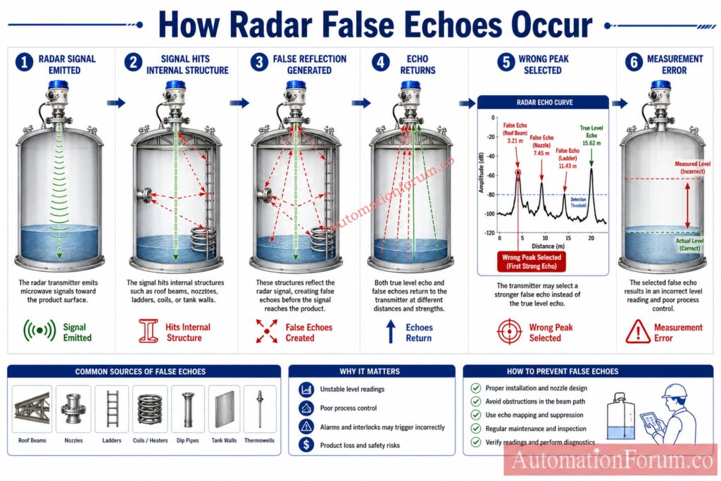
A simple way to understand it is this:
- Radar signal leaves the antenna
- It hits an internal object or obstruction
- It returns as a reflected signal
- The transmitter mistakes it for the surface echo
This is why false echo troubleshooting is such an important skill for instrumentation engineers and maintenance teams.
Eliminate Recurring Failures Using These Expert Maintenance Techniques: Guided Wave Radar Level Transmitters: Complete Troubleshooting & Maintenance Guide
Difference Between Actual Echo and False Echo
| Item | Actual Echo | False Echo |
| Origin | Product surface | Wall, nozzle, internal structure, buildup, or roof detail |
| Movement | Changes with actual level | May remain fixed or move differently |
| Result | Correct level measurement | Incorrect level indication if not rejected |
| Plant impact | Reliable operation | False alarms, unstable control, confusion |
A true echo follows the actual process level. A false echo stays linked to the obstruction or unwanted surface that created it.
Discover The Fastest Way To Diagnose Measurement Problems: Step-by-Step Guide for Troubleshooting Radar Level Transmitters
Radar Level Measurement Problems Caused by False Echoes
False echoes usually show up in the field as one or more of the following symptoms.
| Symptom | What It Usually Means | Possible Impact |
| Level fluctuates | The transmitter is seeing more than one usable reflection | Unstable control |
| Sudden level jump | The wrong echo has become dominant | False alarm or operator confusion |
| Reading frozen | The transmitter has lost the true surface echo | Wrong inventory |
| Frequent high alarm | Instrument is tracking an incorrect peak | Production interruption |
| Low level trip | Signal loss or wrong echo selection | Equipment shutdown |
Typical signs seen by technicians include the DCS reading not matching the local gauge, the level changing when the agitator starts, unstable reading during filling, or a fixed value that does not move even though the tank level is changing.
Top Causes of False Echo in Radar Level Transmitters
Internal Tank Structures Causing False Echo
Internal structures are one of the most common causes of radar level measurement errors. Radar energy can reflect from any solid surface in the beam path.
Typical internals include agitators, mixers, baffles, heating coils, support beams, ladders, dip pipes, spray nozzles and thermowells.
These structures produce false echoes by reflecting the signal before it reaches the true product surface.
If the reflection from the structure is stronger than the surface return, the transmitter may lock onto the wrong peak.
In a reactor, an agitator blade can create a strong reflection when it passes through the beam. In a steam heated vessel, a heating coil may produce a stable fixed echo. In a tank with a ladder inside the beam path, the ladder can produce a constant false signal that looks like a level point.
Engineering lesson
If a tank has internal structures, radar installation location becomes critical. A few centimeters of mounting difference can change the echo profile significantly.
Incorrect Radar Transmitter Installation Location
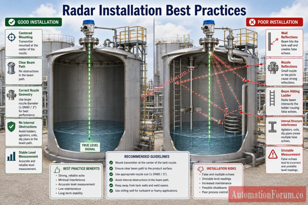
Poor installation is one of the fastest ways to create radar level transmitter false echo troubleshooting problems later.
Common installation mistakes include mounting too close to the tank wall, too close to a nozzle edge, near a filling stream, above an inlet pipe, or in a position where the beam points toward internal obstruction.
When the beam touches the wall or passes near a structure, the reflection pattern becomes complicated. The transmitter may detect a stronger reflection from the wrong point and ignore the actual surface.
A good installation should give the radar beam a clear path. The sensor should be placed where the strongest part of the beam can see the product surface without crossing obvious obstruction zones.
Practical rule
If the installation looks crowded or forced, the echo curve will usually prove it later.
Long Nozzle Reflection Problems
Long nozzles are a major reason for radar level transmitter false reflection issues in non contact radar applications.
A long narrow nozzle can behave like a reflection chamber. The radar signal may bounce inside the nozzle wall, create a trapped echo, and return to the transmitter before the surface echo does. In some cases, the nozzle reflection becomes stronger than the actual product signal.
This is common in tank farms, roof mounted storage tanks, and process vessels where the instrument is installed through a nozzle that was not designed with radar in mind.
Field example
A transmitter on a storage vessel kept showing the same fixed distance even when the tank level changed. The cause was not the process. It was the long nozzle reflection. Once the nozzle geometry was checked and the echo map was updated, the reading became stable.
Best practice
Always confirm nozzle length, nozzle diameter, and vendor recommendations before commissioning radar. If the nozzle is already installed, use echo curve diagnostics and mapping to understand how much it affects the signal.
Foam and Surface Turbulence in Radar Level Measurement
Foam and turbulence are common process reasons for radar level measurement problems.
Foam can absorb or scatter microwave energy. Light foam may still allow a usable echo, but dense foam can weaken the return and make the transmitter track the wrong surface. In some cases, the instrument may read the foam surface while operators want the liquid surface below it.
Turbulence creates a different problem. Waves, splashing, inlet turbulence, and agitation can change the reflection point continuously. The transmitter may then jump between peaks or show a noisy trend.
This is especially common in reactors, separators, wastewater tanks, and vessels with high inlet velocity.
Engineering lesson
When foam or turbulence is present, the issue is not only the transmitter. The process condition itself must also be considered.
Everything Engineers Need To Know About This Technology: What is a Guided Wave Radar (GWR) Level Transmitter?
Product Buildup and Antenna Contamination
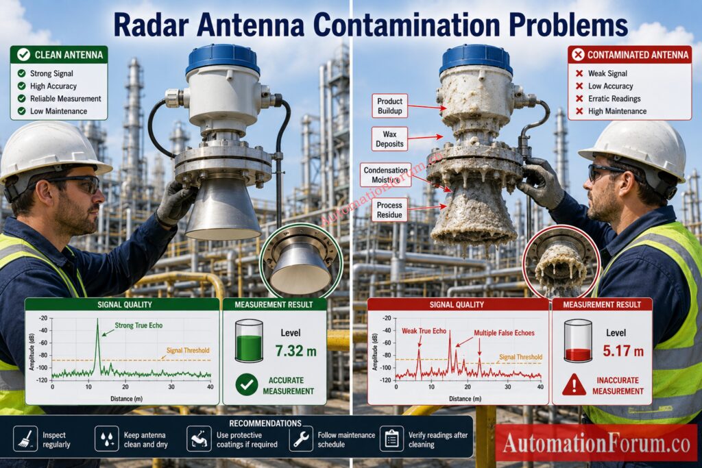
Product build up on the antenna is another major cause of radar level transmitter false alarm and drift.
Typical contamination includes wax, dust, crystallization, condensation, sticky product coating, corrosion residue, and process film. When the antenna is covered, the shape of the radiating surface changes and the signal quality reduces. The transmitter may then receive weak or distorted echoes.
In a sticky process, the problem may develop slowly over weeks or months. This makes it look like calibration drift when the real cause is contamination.
Antenna cleanliness is especially important in chemical, food, pulp, sludge, and slurry applications.
Field tips
If the radar was working well after commissioning and slowly became unstable over time, inspect the antenna first.
Low Dielectric Constant Product Effects
Radar reflects better from products with higher dielectric constant. Low dielectric products produce weaker surface echoes.
This is common in hydrocarbon service, light oils, solvents, and some refined products. When the true surface echo is weak, false echoes from nozzles, walls, and internals become more attractive to the transmitter.
Low dielectric service does not mean radar cannot work. It means the installation must be better, the echo curve must be reviewed carefully, and false echo suppression becomes more important.
Prevent Installation Mistakes Before They Become Costly Failures: Guided Wave Radar Level Transmitter Installation Checklist
How to Read Radar Echo Curve Diagnostics
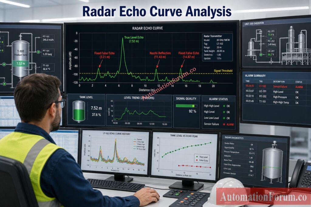
What the Echo Curve Shows
Echo curve analysis is one of the most important skills in radar level transmitter troubleshooting.
The echo curve shows signal strength against distance. A technician can use it to identify the actual level echo, false reflections, blocked zones, and signal stability.
What to look for
- Echo peak height
- Location of the Peak
- Maximum stability
- Number of reflections
- Genuine and fake peaks are different.
- Process Movement Curve Change
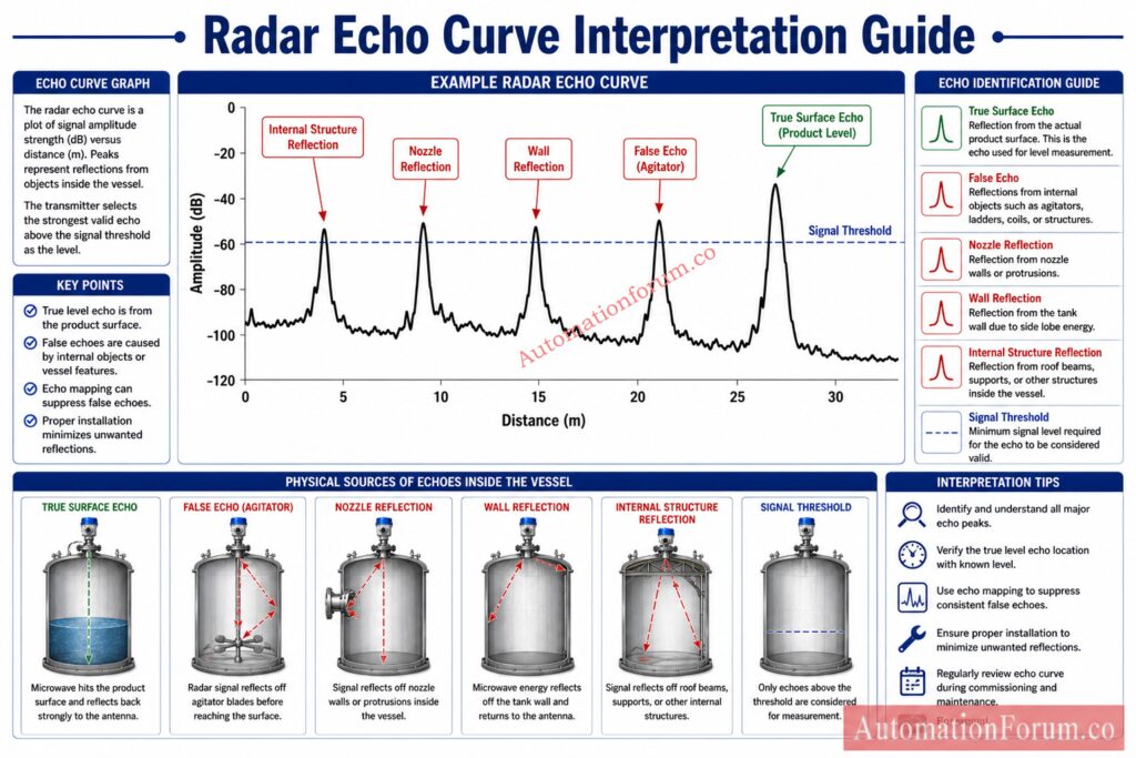
How to Identify the True Surface Peak
A excellent echo curve contains one distinct dominant peak from the product surface and weaker undesirable reflections elsewhere. The transmitter can readily recognize the correct signal.
How to Detect Fixed False Peaks
A poor curve will have many strong peaks, weak or unstable surface return, or a fixed peak that remains at the same position even when the tank level changes.
Multiple Peak Echo Curve Troubleshooting
In vessels with internal structure or complex nozzle geometries, several peaks are typically observed. The engineer must compare the curve with the actual tank condition and determine which peak belongs to the true surface.
Practical interpretation
- If the peak moves exactly with the actual level, it is likely the valid echo.
- If the peak stays fixed, it is likely a false echo.
- If the transmitter is following the wrong peak, false echo suppression or remapping is needed.
Step-by-Step Radar Level Transmitter False Echo Troubleshooting
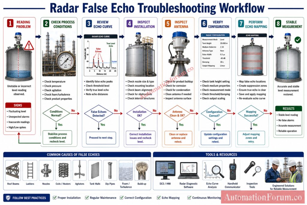
Step 1 Verify Actual Process Conditions
Start with the process before changing the instrument.
- Check the actual level with a local gauge if available
- Check whether foam is present
- Check whether the tank is being filled or emptied
- Check whether agitators or mixers are operating
- Check whether the product has changed
Sometimes the radar is not faulty. The process condition is simply different from the condition during commissioning.
Step 2 Review the Echo Curve Diagnostics
Open the transmitter diagnostics and examine the echo curve carefully.
- Check whether the echo is strong or weak
- Check whether the peak is stable
- Check whether there are multiple peaks
- Check whether the transmitter is tracking the wrong reflection
- Compare the curve with the actual tank condition
The echo curve is often the fastest route to the root cause.
Everything Engineers Need To Know About This Technology: What is a Guided Wave Radar (GWR) Level Transmitter?
Step 3 Inspect Radar Installation and Beam Path
A good installation review often solves the problem quickly.
| Inspection Item | What To Check |
| Mounting point | Too close to wall, nozzle, or inlet |
| Nozzle | Too long, too narrow, or reflective |
| Beam path | Any internal structures in the path |
| Alignment | Sensor vertical and correctly aimed |
| Tank geometry | Roof shape or cone causing reflection |
If the installation looks crowded, the echo curve usually confirms it.
Step 4 Check Antenna or Probe Condition
Inspect the antenna or probe physically.
- Look for buildup
- Look for corrosion
- Look for moisture
- Look for damage
- Look for coating or condensation
A dirty antenna can reduce signal strength and create misleading reflections. This is common in sticky, wet, or dusty service.
Step 5 Verify Instrument Configuration
Incorrect configuration can create wrong output even if the signal itself is acceptable.
- Check empty distance
- Check full distance
- Check dead band
- Check blocking distance
- Check tank height
- Check output scaling
- Check mapping data
If these values do not match the actual vessel, the transmitter will report the wrong level.
Step 6 Perform False Echo Mapping
If the process, installation, and configuration are all reasonable but the transmitter still reads incorrectly, perform false echo mapping.
Mapping allows the instrument to remember unwanted fixed reflections so it can ignore them during normal operation.
Select The Perfect Instrument Every Time With Confidence: Level Transmitter Selection Checklist for EPC Engineers – Step-by-Step Guide
How to Perform Radar False Echo Mapping
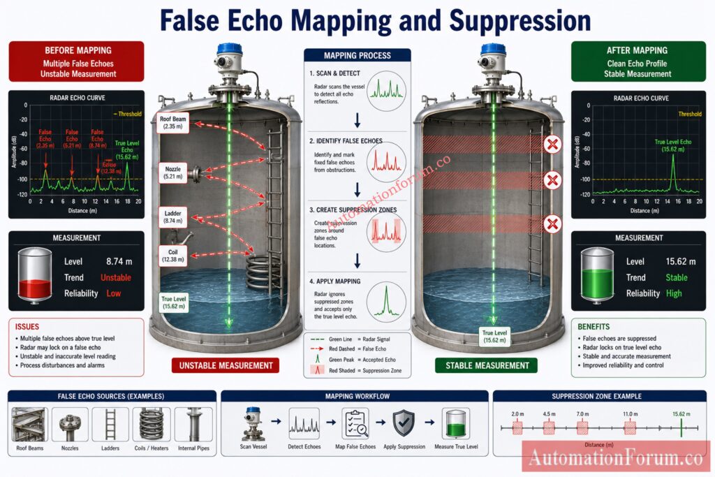
Echo mapping is one of the most useful tools in radar level transmitter troubleshooting.
The transmitter stores the position of fixed false reflections and suppresses them during normal measurement. This helps it focus on the true product surface.
When to Use Echo Mapping
Mapping works best when:
- The vessel condition is stable
- The antenna is clean
- The installation is already verified
- The level condition used for mapping is appropriate
Mapping should be treated as a diagnostic and configuration step, not as a replacement for poor installation.
When to repeat mapping
- After installation
- After cleaning
- After maintenance
- After nozzle modification
- After vessel internal changes
- After major product changes
- After process changes affecting echo quality
Common Mistakes During Echo Mapping
Mapping while foam, turbulence, or temporary disturbances are present. This can teach the transmitter the wrong reference.
Benefit of proper echo suppression
- Stable level reading
- Fewer false alarms
- Better inventory accuracy
- Less operator intervention
- Improved process reliability
Avoid Critical Boiler Measurement Errors Using These Methods: Understanding Boiler Drum Level Transmitters: Accurate DP Measurement Explained
Guided Wave Radar False Echo Troubleshooting
Guided wave radar has its own troubleshooting patterns because the signal travels along a probe.
Common issues include probe buildup, wrong probe length, probe touching internal structures, spacer reflections, probe bending, and coating on the probe.
Troubleshooting method for guided wave radar
- Inspect the probe condition
- Check whether the probe touches the vessel internals
- Verify probe length and mounting arrangement
- Review the echo curve along the probe path
- Clean coating or buildup if present
- Repeat calibration if the signal profile changed
Guided wave radar is often used in difficult service, but it still needs correct installation and regular maintenance.
Explore The Technology Trusted For Difficult Level Applications: Submersible Level Transmitters: Applications, Working Principles, and Benefits
Non Contact Radar False Echo Troubleshooting
Non contact radar is more sensitive to beam path and vessel geometry.
Common causes include wall reflection, nozzle reflection, roof reflection, ladder reflection, and other internal structure reflections.
What to check
- Beam angle
- Mounting position
- Nozzle geometry
- Internal structure clearance
- Roof and wall reflections
- Alignment of the transmitter
If the beam sees too much metal or geometry, false echo risk increases sharply.
Uncover Accuracy Factors Most Engineers Commonly Overlook: Understanding the Factors Influencing the Accuracy of Ultrasonic Level Measurement
Real Plant Case Studies of Radar False Echo Problems
Case Study 1 Radar transmitter reading 100 percent despite half full tank
A refinery storage tank showed full level on the DCS even though the actual product level was about half full.
The investigation showed a strong fixed reflection from an internal roof beam. The transmitter had locked onto that reflection because the echo map had not been updated after vessel modification.
The root cause was a fixed false echo from an internal structure. The corrective action was to clean the antenna, review the mounting point, and perform new false echo suppression mapping.
The lesson learned was simple. Any tank modification should trigger a review of radar diagnostics and mapping.
Case Study 2 False high high alarm during agitator operation
A chemical reactor repeatedly generated high high alarms when the agitator started.
The echo curve changed during mixer operation and the transmitter followed a strong blade reflection instead of the liquid surface.
The root cause was agitator reflection combined with surface disturbance. The corrective action was to review mounting position and re evaluate the echo curve during normal operating condition.
The lesson learned was that moving internals can create false echoes only during operation, which makes the problem look intermittent.
Compare Every Major Technology In One Practical Guide: Mastering Level Measurement Technologies: A Comprehensive Guide
Case Study 3 Level fluctuations caused by foam
A separator in process service showed unstable level during foaming conditions.
The radar signal became weaker because foam scattered the microwave energy. The transmitter then jumped between surface signals and gave a noisy trend.
The root cause was foam and mixed reflection behavior. The corrective action was to check process foam control and adjust the radar settings where possible.
The lesson learned was that foam is not only a process issue. It is also a measurement issue.
Case Study 4 Long nozzle causing persistent false echoes
A radar transmitter installed on a long narrow nozzle gave a fixed wrong reading after commissioning.
Inspection showed that the nozzle wall was creating a strong reflection inside the nozzle body. The surface echo was present but weaker.
The root cause was nozzle reflection amplification. The corrective action was to review nozzle geometry and perform proper echo mapping.
The lesson learned was that long nozzles can act like reflection chambers.
Learn Why Tank Geometry Impacts Measurement Performance: Effect of Tank Design on Accuracy of Level Measurement
Case Study 5 Antenna contamination causing measurement drift
A radar transmitter in pharmaceutical service slowly drifted upward over time.
When the antenna was inspected, fine product film and condensation were found on the sensor face. The contamination distorted the signal shape.
The root cause was antenna contamination. The corrective action was cleaning, rechecking the curve, and verifying the output against the actual vessel condition.
The lesson learned was that slow drift often indicates contamination rather than electronics failure.
Perform Accurate Calibration Calculations Without Complex Math: Excel tool for DP type level and density transmitter calibration range calculation
Radar Level Transmitter False Echo Troubleshooting Checklist
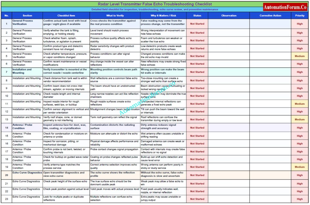
This checklist is designed to help instrumentation and maintenance teams quickly identify radar false echo issues by checking the process condition, installation, antenna condition, echo curve, configuration, and echo mapping. It is built from the attached radar level transmitter false echo troubleshooting content and is meant for practical field use.
Master This Reliable Technique Used Across Industries: Bubbler method level measurement principle and installation
Best Practices to Prevent False Echo in Radar Level Transmitters
False echo problems are much easier to prevent than to fix later.
Proper radar installation starts with correct mounting location. The beam should have a clear path to the product surface. The nozzle should follow vendor guidance. Internal structures should be avoided where possible. The antenna should be kept clean. Echo mapping should be performed after installation and repeated whenever the vessel changes.
Routine diagnostics review is also important. If the curve changes slowly over time, it may indicate buildup or process changes. If the curve changes suddenly, it may indicate a new reflection path or a mechanical modification.
Practical best practice summary
- Use proper mounting
- Avoid beam obstruction
- Follow nozzle recommendations
- Inspect the antenna regularly
- Verify configuration carefully
- Repeat mapping after maintenance
- Review diagnostics during shutdown rounds
Improve Interface Detection Accuracy Using Proven Engineering Practices: Interface level measurement using DP transmitter (Remote sealed)
Frequently Asked Questions on Radar Level Transmitter False Echo Troubleshooting
What is the cause of false echo on radar?
False echoes in a radar level transmitter are usually caused by tank internals, nozzle reflections, wall reflections, buildup, foam, or poor mounting location.
The transmitter may mistake these unwanted reflections for the actual product surface.
What are echoes in a radar system?
In a radar level transmitter, echoes are the reflected microwave signals that return after hitting a surface inside the tank.
The instrument uses the strongest valid echo to calculate level.
What causes second trace echoes?
Typical causes of second trace echoes include internal reflections, numerous bounce signals, and loud echoes from nozzles, walls and tank structures.
They are visible as additional peaks in the echo curve and may confuse the transmitter.
How to calibrate a radar level transmitter?
Calibration is to adjust the correct empty distance, full distance, dead band and blocking distance for the tank.
Then check the echo curve and do false echo mapping if necessary.
What causes false echoes in radar level transmitters?
Internal structures, nozzle reflections, wall reflections, accumulation, foam, turbulence, or poor mounting placement can create false echoes.
Such unwanted reflections can disturb the genuine level signal and incorrect readings can be produced.
How do I identify false echoes from actual level echoes?
Compare the echo curve to the actual tank level, and look for stable peaks that do not move with the product surface.
The true echo changes with level, while false echoes usually stay at the same distance.
What is radar false echo suppression?
Radar false echo suppression is the process of teaching the transmitter to ignore unwanted fixed reflections.
This makes the device focuses on the genuine level echo and increases the stability of the measurement.
When should echo mapping be performed?
Echo mapping should be done after installation, after cleaning, after maintenance, after nozzle changes, and after vessel modifications.
It should also be repeated if the echo curve changes or the reading becomes unstable.
Why is my radar level transmitter reading unstable?
Unstable reading may be caused by foam, turbulence, weak echo strength, contamination, or wrong echo selection.
A poor installation or changing process condition can also make the signal jump.
Can foam create false echoes?
Foam can reduce or scatter the radar signal, resulting in unstable or misleading results.
In heavy foam service, the transmitter may read the foam surface rather than the real liquid level.
How does nozzle length affect radar performance?
Long, thin nozzles can capture reflections and generate significant false echoes in the nozzle.
This may result in a fixed read, erroneous echo selection or unstable level output.
Can agitators affect radar level measurement?
Yes, agitators can be a source of both reflection and turbulence difficulties in a radar level transmitter.
When the mixer runs, the echo curve may change and the transmitter may lock onto the wrong signal.
Is radar better than ultrasonic for difficult tanks?
Often yes, because radar is usually less affected by vapour, pressure, temperature, and acoustic noise.
That is why radar level measurement is preferred in many process vessels and storage tanks.
What is the most common cause of radar false echo?
Installation mistakes and internal tank reflections are among the most common causes of radar false echo.
A poor beam path or wrong nozzle position can easily create measurement errors.
How do I know whether antenna contamination is the issue?
If the reading drifts slowly over time and the antenna shows coating or condensation, contamination is likely the cause.
Cleaning the antenna and checking the echo curve usually confirms the issue.
Can low dielectric products create more false echo problems?
Yes, low dielectric products give weaker surface reflections, so false echoes can dominate more easily.
This is common in hydrocarbon, solvent, and light oil service.
Should I recalibrate after cleaning the antenna?
Yes , after cleaning the antenna check the echo curve and compare the reading with the actual level .
Cleaning can modify the profile of the signal thus it’s always a good idea to check.
Can a tank wall reflection be stronger than the level echo?
Yes, especially at bad mounting conditions or low-dielectric service.
If the wall reflection is bigger, the transmitter may follow the wall instead of the genuine product surface.
What is the best first troubleshooting step?
Check process conditions first, then check echo curve, then check installation and antenna condition, then check configuration and mapping.
This sequence gives the fastest path to root cause in radar level transmitter troubleshooting.
Diagnose Difficult Transmitter Issues With Confidence And Speed: Troubleshooting of DP Type Level Transmitter
Conclusion: Key Takeaways for Reliable Radar Level Measurement
Radar level transmitter false echo troubleshooting requires a combination of process understanding, installation review, echo curve analysis, and proper configuration. Most problems do not come from the transmitter alone. They usually come from the interaction of tank geometry, internal structures, nozzle design, foam, buildup, contamination, and mapping errors.
How to Reduce Radar Level Transmitter False Echo Problems
The major causes of radar level measurement problems are internal obstructions, poor installation location, long nozzle reflections, foam, turbulence, antenna contamination, and low dielectric product service. The best diagnostic path is to verify the process condition, inspect the installation, review the echo curve, check the antenna, and perform echo mapping when needed.
For instrumentation and maintenance teams, the goal is to keep the beam path clear, keep the antenna clean, verify the transmitter configuration, and review the echo profile whenever the process changes. That approach reduces downtime, improves measurement reliability, prevents false alarms, and gives operators better confidence in the level signal.
Refer the below link for the Radar Level Transmitter Calculator for Tank Level Measurement