
- Introduction to PLC Input Signal Failure
- What Is PLC Input Signal Failure?
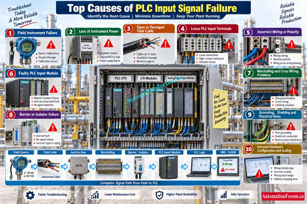
- Top Causes of PLC Input Signal Failure in Plants
- Field Instrument Failure
- Loss of Instrument Power Supply
- Open or Damaged Field Cable
- Loose or Damaged PLC Input Terminals
- Incorrect PLC Input Wiring or Polarity
- Faulty PLC Input Module or Input Channel
- PLC Marshalling and Cross Wiring Problems
- Signal Barrier or Isolator Failure
- Grounding Shielding and Electrical Noise Problems
- Incorrect PLC Hardware Configuration and Scaling
- PLC Analog Input Signal Failure
- PLC Digital Input Signal Failure
- Step by Step PLC Input Troubleshooting Procedure
- Step 1: Check the Field Device
- Step 2: Check the Instrument Power Supply
- Step 3: Check Field Terminals and Junction Box
- Step 4: Check the Field Cable
- Step 5: Check Marshalling Terminals
- Step 6: Check Signal Barrier or Isolator
- Step 7: Check the PLC Input Terminal
- Step 8: Check the PLC Input Module
- Step 9: Check PLC Hardware Configuration
- Step 10: Check PLC Input Address and Channel Mapping
- Step 11: Check PLC Scaling and Engineering Units
- Step 12: Check PLC Logic
- Step 13: Check HMI or SCADA Indication
- Practical PLC Input Signal Troubleshooting Example
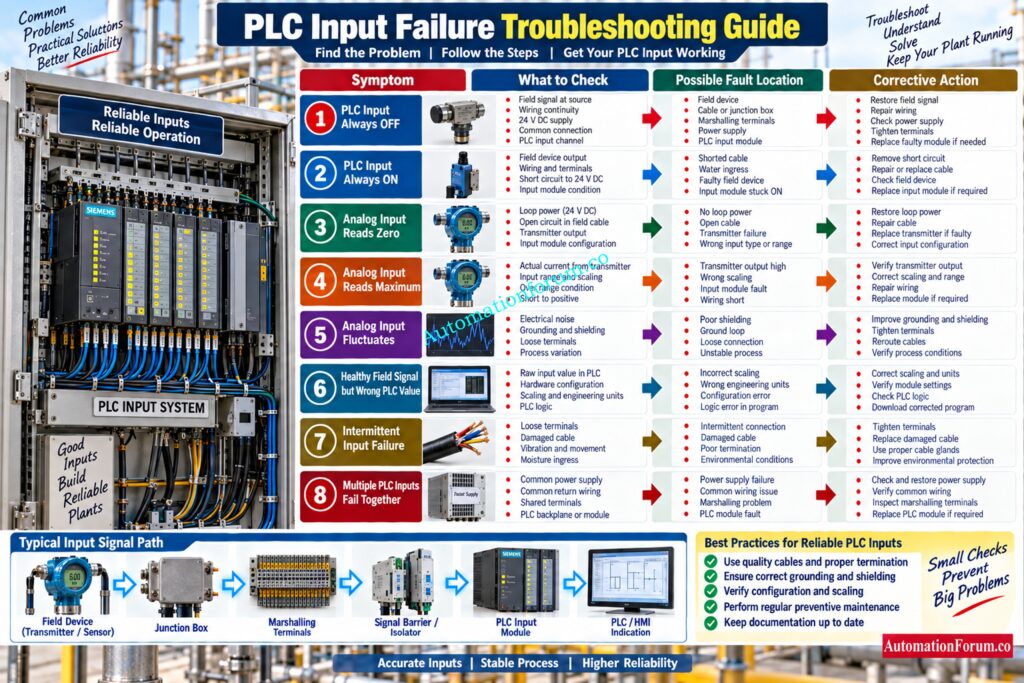
- PLC Input Failure Troubleshooting Table
- How to Prevent PLC Input Signal Failure
- Common PLC Input Troubleshooting Mistakes
- Frequently Asked Questions About PLC Input Signal Failure
- Why does a PLC input signal fail?
- How do you troubleshoot a PLC input?
- Why is a 4 to 20 mA signal not reaching the PLC?
- What causes a PLC digital input to remain OFF?
- How do you test a PLC input module?
- What causes fluctuating PLC analog input signals?
- How can PLC input failures be prevented?
- What are the common causes of PLC failure?
- What are the common causes of PLC output failure?
- What are the 5 main components of a PLC?
- How to check PLC input and output?
- What input voltage is necessary for the PLC?
- Conclusion: PLC Input Signal Failure Troubleshooting
Introduction to PLC Input Signal Failure
PLC input signal failure is one of the most common troubleshooting problems in industrial plants. A transmitter may be healthy, the process may be normal, and the PLC may still show an incorrect or missing value.
The reason is simple. A field signal does not travel directly from the instrument to the PLC program. It normally passes through field wiring, junction boxes, terminals, marshalling systems, barriers or isolators where applicable, and finally the PLC input module. The PLC then processes the signal according to its hardware configuration, scaling, address mapping, and logic.
A good troubleshooting engineer does not immediately replace the PLC input module. The better approach is to trace the signal from the field device toward the PLC and prove where the signal is being lost or changed.
What Is PLC Input Signal Failure?
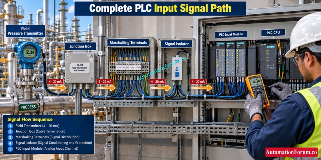
What Happens When a PLC Input Signal Fails?
PLC Input Signal Failure . This failure occurs when the PLC either does not receive the expected electrical signal from a field device or does not correctly interpret the received signal.
Common Symptoms of PLC Input Signal Failure
The problem may appear as:
- No signal reaching the PLC
- Incorrect signal reaching the PLC
- Unstable or fluctuating signal
- Healthy field signal but no PLC indication
- Correct electrical signal but incorrect engineering value
- Correct PLC input status but incorrect PLC logic response
Where Can PLC Input Signal Failure Occur?
Top Causes of PLC Input Signal Failure in Plants
Field Instrument Failure
A failed transmitter, switch, proximity sensor, pressure switch, or position feedback device can prevent the expected signal from reaching the PLC.
Check the local instrument indication and compare it with the actual process condition. For an analog transmitter, measure the actual output signal rather than assuming that the transmitter is healthy.
Loss of Instrument Power Supply
A two wire transmitter depends on its loop power. If the 24 V DC supply is missing or significantly reduced, the transmitter may stop producing the expected signal.
Check the supply at the transmitter terminals, not only at the power supply output.
PLC Input Is ON Yet Nothing Happens? Investigate Here: PLC Input ON but Output Not Energizing: Complete Troubleshooting Guide
Open or Damaged Field Cable
Broken conductors, damaged cables, poor cable glands, or water ingress can interrupt the signal.
An open circuit in a 4 to 20 mA loop can produce a zero current condition and may also activate a channel wire break diagnostic depending on the PLC module.
Loose or Damaged PLC Input Terminals
Loose terminals are particularly common in plants with vibration, repeated maintenance activity, or poorly maintained panels.
A loose connection can produce an intermittent PLC input fault that disappears when the panel is disturbed. Check the complete signal path rather than only the PLC terminal.
Poor Alarm Records Can Hide Serious PLC Problems: PLC Alarm and Trip Documentation Procedure – EPC PLC Automation Engineer Guide
Incorrect PLC Input Wiring or Polarity
Incorrect termination can prevent a signal from reaching the PLC.
This is especially important with 4 to 20 mA circuits because transmitter topology and polarity must match the input arrangement. Two wire, three wire, and four wire transmitters require different wiring arrangements.
Faulty PLC Input Module or Input Channel
An input module can fail because of electrical damage, component failure, excessive voltage, short circuit, or environmental conditions.
If the signal is proven at the PLC terminal but the channel does not respond correctly, investigate the input module and its channel diagnostics.
PLC Permissive Blocking Your Process? Trace The Logic First: PLC Permissive Logic Troubleshooting Procedure for Instrumentation Engineers
PLC Marshalling and Cross Wiring Problems
Incorrect marshalling can connect a healthy field signal to the wrong PLC channel.
This can create a confusing situation where the PLC appears to have an input fault while the actual problem is incorrect termination or channel mapping.
Signal Barrier or Isolator Failure
Intrinsic safety barriers, signal isolators, splitters, and signal conditioners can affect the signal path.
Measure the signal entering and leaving the device where approved test procedures allow it. A healthy signal entering an isolator but an incorrect signal leaving it immediately narrows the fault location.
Why Does Industry Rely So Heavily On 24 V?: Why is 24 Volts Mostly used in Industrial PLC Systems?
Grounding Shielding and Electrical Noise Problems
Fluctuating analog inputs are often associated with poor shielding, grounding problems, ground loops, VFD interference, or damaged signal cables.
First determine whether the actual field current is fluctuating. If the value of the PLC varies while the current in the field is stable, check the input channel, reference arrangement, settings and filtering.
Incorrect PLC Hardware Configuration and Scaling
The hardware is perfectly healthy, however the PLC may show an inaccurate value.
For analog inputs, verify the selected signal type, input range, channel configuration, raw value, scaling, and engineering units. A 4 to 20 mA signal connected to an incorrectly configured input can produce misleading values even though the field signal is correct.
Refer the below link for the 4-20 mA Loop Troubleshooting with Loop Calibrators : A Practical Guide
PLC Analog Input Signal Failure
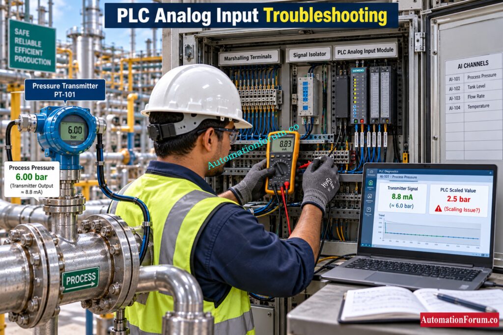
4 to 20 mA PLC Input Signal Problems
Analog input problems commonly involve 4 to 20 mA and 0 to 10 V signals.
For a standard 4 to 20 mA transmitter:
- 4 mA represents 0 percent.
- 12 mA represents 50 percent.
- 20 mA represents 100 percent.
A reading of 0 mA normally indicates that the loop requires investigation because a healthy 4 to 20 mA loop uses a live zero. Possible causes include loss of power, an open circuit, incorrect wiring, a failed transmitter, or an intermediate device problem.
PLC Failure Risk Too High? Understand Hot Standby Architecture: Hot Standby in PLC Systems: Architecture, Working, and Benefits
4 to 20 mA PLC Input Calculation Example
Assume a pressure transmitter with a range of 0-10 bar.
The intended relationship being:
4 mA = 0 bar
12 mA = 5 bar
20 mA = 10 bar
The process value is calculated by:
Process value = 10 × (Signal current minus 4) divided by 16
If the measured signal is 14 mA:
Process value = 10 × (14 minus 4) divided by 16
Process value = 6.25 bar
If the transmitter is showing 14 mA, but the PLC is reading 4 bar, check PLC scaling or settings before replacing the transmitter.
Prevent I/O Failures Before They Stop Plant Operations: Proactive Maintenance Strategies for PLC I/O Modules: Reduce Downtime & Improve Reliability
PLC Digital Input Signal Failure
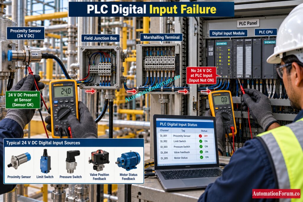
Digital inputs are common for limit switches, pressure switches, level switches, proximity sensors, motor feedback, valve position feedback and other status signals.
For a typical 24 V DC input, the engineer should check that the required voltage is truly present at the PLC input terminal.
For example if a proximity sensor is expected to generate about 24 V DC when active, measure the signal at the sensor output and then at the PLC input terminal using an approved test procedure.
If you have 24 V DC at the sensor but not at the PLC terminal, check cable, junction box, terminals and marshaling.
If the PLC input terminal is 24 V DC, yet the PLC input is OFF, check the input channel, common connection, configuration and module diagnostics.
Is Your Current Loop Failing? Find The Fault Fast: How to do troubleshooting of a 4-20mA loop?
Step by Step PLC Input Troubleshooting Procedure
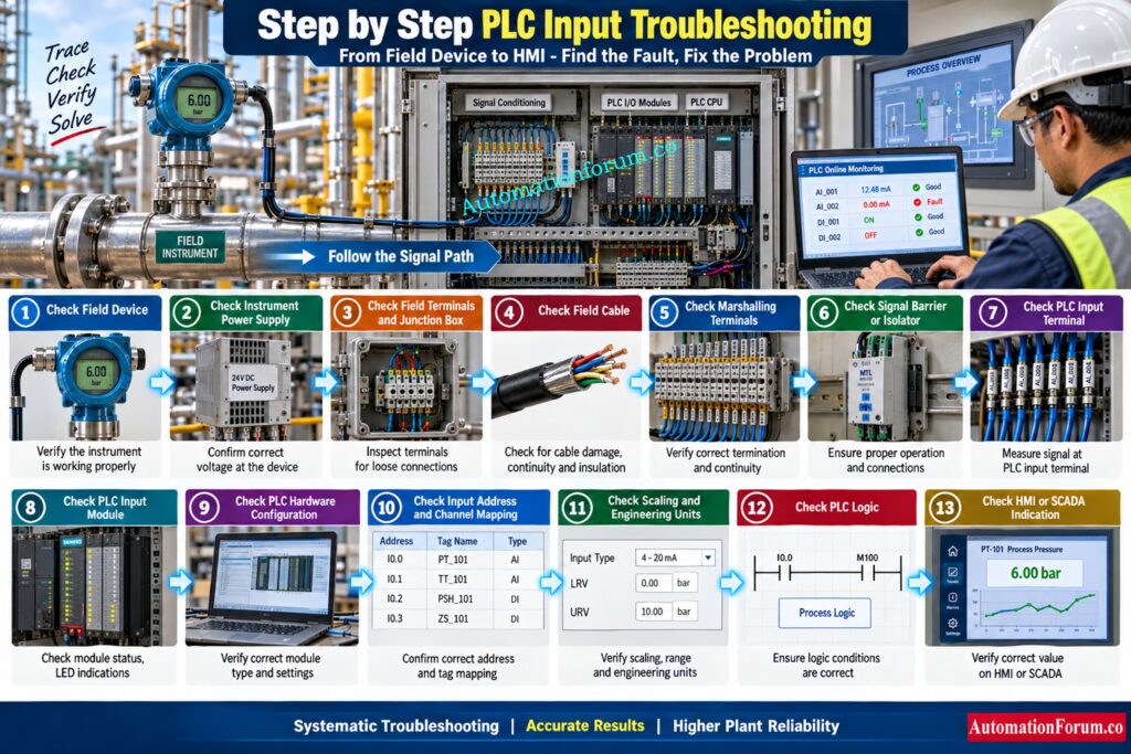
A methodical way of troubleshooting a PLC input helps engineers to trace the signal from the field device to the PLC and to find the real cause of failure promptly.
Step 1: Check the Field Device
First, verify the operation of the transmitter, sensor, switch or other field equipment.
Compare its local indicator and actual output to the process condition envisaged.
Step 2: Check the Instrument Power Supply
Make sure that the field instrument is getting the correct power source and the voltage is within the range specified by the manufacturer.
A healthy instrument can also report a PLC input failure because of a power supply problem.
Voltage Drop Could Be Silently damage Your PLC Signals: How to Calculate and Minimize Voltage Drop in PLC Wiring?
Step 3: Check Field Terminals and Junction Box
Inspect field terminals and junction box for loose connections, damaged terminals, dampness or inappropriate termination.
Step 4: Check the Field Cable
Check the field cable for open circuits, broken conductors, insulation difficulties or other wiring flaws.
For analog transmissions, compare the measured current at each end of the field and the PLC to see where the signal is being lost.
Step 5: Check Marshalling Terminals
Check that the field signal is linked to the correct marshaling terminal and PLC channel.
A healthy signal can be sent to the wrong PLC input by incorrect termination or cross wiring.
Step 6: Check Signal Barrier or Isolator
Test operation of the signal isolator, signal conditioner, or intrinsic safety barrier as appropriate.
Check the signal in and out of the device to see whether it is interfering with the PLC input signal.
Missing PLC Documentation Can Create Major Troubleshooting Delays: PLC System Documentation Guide: Essential Records for Industrial Automation
Step 7: Check the PLC Input Terminal
Use an approved plant testing approach to measure voltage or current really arriving at the PLC input port.
This phase verifies that the PLC panel receives the expected field signal correctly.
Step 8: Check the PLC Input Module
“Input module status, channel indication, common connections, and accessible diagnostic information.
If the terminal receives the right signal but the channel does not reply, check the input module or individual input channel.
Step 9: Check PLC Hardware Configuration
Ensure that the PLC input module and individual channel are set for the correct signal type and operating range.
A healthy field signal may be read inaccurately due to an inappropriate hardware configuration.
Need To Prove Your Analog Input Works? Try This: How to simulate 4-20ma signal with Loop Calibrator ?
Step 10: Check PLC Input Address and Channel Mapping
Check that the physical input channel is mapped to the right PLC address and tag.
If the address or channel is set incorrectly, the PLC may appear to have an input failure while in fact the signal is going to a different channel.
Step 11: Check PLC Scaling and Engineering Units
For analog inputs check engineering units, scaling calculation, signal range, raw input value.
If the scaling is improper it can result in the PLC showing a wrong process value for a perfectly OK input signal.
Step 12: Check PLC Logic
If PLC input status and raw signal are correct, verify program logic, interlocks, permissives and tag processing.
A logic or programming error might cause a correct input signal to not generate the desired control response.
Wrong PLC Data Types Can Create Costly Control Errors: PLC Data Types Every Automation Engineer Must Know to Avoid Costly Programming Errors
Step 13: Check HMI or SCADA Indication
Last, check the HMI or SCADA screen is connected to the relevant PLC tag.
If PLC value is valid & HMI shows wrong value then check tag mapping, communication, HMI settings.
Refer the below link for the Step-by-Step Procedure to Troubleshooting Solenoid Valves in PLC Digital Output Loops
Practical PLC Input Signal Troubleshooting Example
A pressure transmitter indicates 6 bar on the local display, but the PLC reads zero.
The engineer checks the transmitter output first and reads about 13.6 mA. The transmitter is therefore producing a reasonable signal for a 0 to 10 bar range.
The engineer then checks the 24 V DC supply and confirms that adequate voltage is available at the transmitter.
Next, the signal is checked through the field terminals and marshalling terminals. The same current reaches the PLC input terminal.
The PLC channel is then checked. The input module reads the current, but the value of PLC engineering is still wrong.
The engineer reviews the channel settings and sees that the program scaling does not match the transmitter range.
The hardware was healthy. The actual problem was configuration.
This is why signal tracing is more reliable than immediately replacing an input module.
One Missing PLC Backup Could Cost Hours Of Recovery: Programmable Logic Controller (PLC) Program Backup Checklist
PLC Input Failure Troubleshooting Table
| Observed symptom | Possible cause | Recommended check | Corrective action |
| PLC input always OFF | No field signal or wiring fault | Measure field and PLC terminal voltage | Repair signal path |
| PLC input always ON | Short circuit or failed device | Check field output and wiring | Correct wiring or replace device |
| Analog input reads zero | Open loop or power loss | Measure loop current and supply | Restore loop |
| Analog input reads maximum | Over range or scaling problem | Check actual current and configuration | Correct fault or scaling |
| Analog input fluctuates | Noise, grounding or loose connection | Compare field current with PLC value | Correct wiring or grounding |
| Healthy field signal but wrong PLC value | Configuration or scaling error | Check raw value and engineering range | Correct configuration |
| Intermittent input failure | Loose terminal or damaged cable | Inspect connections and cable | Repair connection or cable |
| Multiple inputs fail together | Common power or common return problem | Check shared supply and terminals | Restore common circuit |
Motor Starting Problems? Check This Critical PLC Interlock: PLC Program for Motor Starter with Low-Level Switch Interlock
How to Prevent PLC Input Signal Failure
- Good engineering methods can help reduce PLC input signal issues considerably.
- Use suitable instrumentation cable and keep signal wires far apart from high voltage circuits. Use proper shielding and grounding techniques. Add appropriate surge protection as necessary.
- Commissioning: Perform full loop check from field device to PLC and HMI. Check electrical signal values and engineering values shown.
- Accurate PLC hardware configuration and loop documentation. Periodically check terminals, marshaling systems, power supply and field connections.
- Keeping suitable spare input modules and maintaining PLC diagnostic monitoring can also reduce plant downtime.
Wrong PLC Wiring Type? Sinking And Sourcing Explained: Sinking and Sourcing: Which Connection is Best for Your PLC?
Common PLC Input Troubleshooting Mistakes
One of the biggest mistakes is immediately replacing the PLC input module.
Other common mistakes include:
- Checking only the PLC screen
- Ignoring field power
- Not measuring the actual signal
- Assuming the transmitter has failed
- Ignoring common terminals
- Ignoring PLC scaling
- Ignoring hardware configuration
- Overlooking intermittent wiring
- Failing to trace the complete signal path
The best troubleshooting question is not “Which component should I replace?” It is “At which point does the expected signal disappear or change?”
Analog Input Card Failed? Follow This Safe Replacement Process: Replacing a Faulty Analog Input Card in a PLC Rack in Continuous Process Industries: Step by Step Procedure
Frequently Asked Questions About PLC Input Signal Failure
Why does a PLC input signal fail?
PLC input signal failure can result from faulty instruments, power loss, damaged wiring, loose terminals, failed input channels, or configuration errors.
Other reasons the signal may not be processed correctly as planned are grounding problems, signal conditioning defects, inappropriate scaling and PLC logic flaws.
How do you troubleshoot a PLC input?
Start with the field device and follow the signal through the wire, terminals, marshaling system and PLC input module.
Measure actual signal and check channel diagnostics, PLC configuration, scaling, logic and HMI indication
Why is a 4 to 20 mA signal not reaching the PLC?
Loss of loop power, open wiring, wrong polarity, transmitter failure, loose connections or isolator difficulties can interrupt the 4 to 20 mA signal.
Measure the loop current at various locations to determine exactly where the signal is lost.
What causes a PLC digital input to remain OFF?
A PLC digital input can be OFF due to a malfunctioning field device, lack of 24 V DC supply, open cable, poor wiring or common terminal faults.
If the correct voltage is present at the input terminal of the PLC. Check the input channel, module diagnostics and PLC setup.
How do you test a PLC input module?
Verify that the expected field instrumentation signals are received at the PLC input terminal in accordance with an approved plant testing process.
Next, examine the input channel status, module diagnostics, common connections, hardware configuration, and input response.
What causes fluctuating PLC analog input signals?
Electrical noise, insufficient shielding, grounding difficulties, loose connections, unstable power or process variation might generate fluctuating PLC analog input signals.
Check the transmitter output against the PLC reading to see if the fluctuation is in the field or input circuit.
How can PLC input failures be prevented?
Proper wiring, termination, cable segregation, shielding, grounding, reliable power sources and correct PLC hardware configuration.
Recurring PLC input failures can be minimized through regular loop testing, calibration, preventative maintenance and diagnostic monitoring.
What are the common causes of PLC failure?
PLC failures are usually caused by such things as a bad power supply, over-temperature conditions, electrical damage, communication errors, hardware defects and poor maintenance.
Other reasons for PLC malfunction are wrong configuration, memory problems, grounding problems, wiring problems and harsh plant conditions.
What are the common causes of PLC output failure?
Damage of output channel, wrong wiring, blown protective devices, overload or problems with external power supply might cause PLC output failure.
Faulty PLC logic, interlocks, output configuration, or failed actuators can cause a good output to appear bad.
What are the 5 main components of a PLC?
A PLC has five basic building blocks. These include the CPU, the power supply, the input modules, the output modules, and the programming/communication interface.
The components of these are configured to receive signals from the field, execute control logic and control plant equipment.
How to check PLC input and output?
Verify the field signal, PLC terminal voltage or current, channel status, module diagnostics, hardware setup, and PLC program.
Check the PLC command and then check the output terminal, external power source, wiring and attached load for outputs.
What input voltage is necessary for the PLC?
The PLC input voltage required depends on the particular PLC input module, with 24 V DC being common in industrial control systems.
Be sure to check the input threshold and voltage range stated by the manufacturer prior to testing or connecting a PLC input circuit.
Digital Output Not Working? Trace These Fault Points: Step-by-Step Procedure for Troubleshooting PLC Digital Outputs
Conclusion: PLC Input Signal Failure Troubleshooting
https://automationforum.co/plc-remote-io-communication-failure/Need to be traced methodically from the field device through the power supply, wiring, terminals, marshaling, signal conditioning devices, PLC input channel, configuration, scaling and logic. With this approach, instrumentation and automation professionals may detect defects more quickly, minimize wasteful module replacement, and restore dependable plant performance.
Refer the below link for the PLC Troubleshooting Remote IO Rack Communication Failure Complete Troubleshooting Guide for Industrial Automation Engineers
