
Control Valve Authority Calculator
Control Valve Authority System Schematic
1. Valve Specifications
2. System and Process Data
Quick Load Scenarios
Control Valve Authority Results
Authority Assessment
Installed Flow Characteristic
Inherent Gain vs Installed Gain
Step by Step Engineering Calculation
| Parameter | Calculated Value |
|---|
Valve Authority Calculation
Engineering Interpretation
Governing Engineering Standards
This makes the calculation useful during control valve sizing, detailed engineering, EPC design reviews, commissioning and plant troubleshooting.
- What Is Control Valve Authority?
- Why Is Control Valve Authority Important?
- How Does the Control Valve Authority Calculator Work?
- Control Valve Authority Calculation Formula
- Inherent Versus Installed Control Valve Characteristics
- Control Valve Inherent Gain and Installed Gain
- Control Valve Authority Calculation Example
- What is a Good Control Valve Authority?
- Control valve Authority interpretation table
- How to Use the Control Valve Authority Calculator
- Control Valve Authority Applications in Process Industries
- Control Valve Authority Troubleshooting
- Control Valve Authority Design Considerations
- Control Valve Engineering Best Practices
- Control Valve Authority Standards and Engineering References
- Control Valve Authority Calculator Limitations
- Frequently Asked Questions About Control Valve Authority
- Conclusion: Control Valve Authority for Better Valve Selection and Process Control
What Is Control Valve Authority?
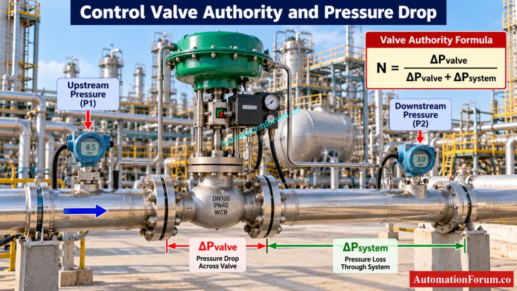
Control Valve Authority Formula
The calculator uses:
N = ΔPvalve / (ΔPvalve + ΔPsystem)
How Valve Pressure Drop Affects Authority
Why Is Control Valve Authority Important?
Effect of Low Valve Authority on Control Performance
A control valve does not operate in isolation. Once installed in a process line, the pressure available across the valve changes as flow changes.
Effect of Valve Authority on Energy Consumption
This can affect control loop performance, process stability and usable valve travel.
Valve Authority During Control Valve Sizing
Avoid Costly EPC Valve Selection Mistakes Before Design: Why Control Valve Characteristics Matter in EPC Instrumentation and Control Engineering
How Does the Control Valve Authority Calculator Work?
The calculator begins with the valve specifications and process conditions required for the analysis. The main inputs are rated Cv at full opening, trim characteristic, specific gravity, maximum design flow, system line loss and valve pressure drop.
Rated Cv Input
Rated Cv represents the valve flow coefficient at full valve opening.
The calculator uses this value to estimate the valve pressure drop when a valve pressure drop is not entered manually.
For liquid service, the calculator uses:
ΔPvalve = SG × (Qmax / Cv100)²
The value normally comes from the valve manufacturer or the control valve sizing calculation.
Trim Characteristic Input
The calculator provides three choices: Linear, Equal Percentage and Quick Opening.
The selected characteristic determines how the valve flow coefficient changes with valve travel.
For the linear characteristic, Cv varies approximately in proportion to valve travel.
For the equal percentage characteristic, the flow coefficient increases exponentially with travel.
For the quick opening characteristic, the calculator represents Cv using a square root relationship.
This selection is important because the inherent characteristic affects the installed flow characteristic after system pressure loss is considered.
Specific Gravity Input
Specific gravity represents the liquid density relative to water.
The calculator uses specific gravity when estimating valve pressure drop and calculating flow from the Cv relationship.
The value should be taken from the process design data at the relevant operating condition.
Maximum Design Flow Input
The calculator uses this value together with rated Cv and specific gravity when estimating valve pressure drop.
Line Loss at Maximum Flow
Line loss represents pressure loss through the piping and associated system resistance excluding the control valve.
The calculator models this loss as increasing approximately with the square of flow:
ΔPline = ΔPline,max × (Q / Qmax)²
This assumption is important because increasing flow increases system resistance and consequently changes the pressure available across the valve.
Valve Pressure Drop
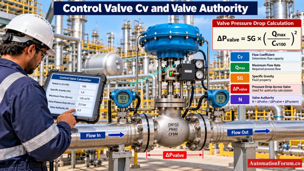
Valve pressure drop can be entered directly.
If the value is left at zero, the calculator estimates it from maximum flow, rated Cv and specific gravity.
Minimum Operating Flow and Maximum Valve Travel
The calculator provides fields for minimum operating flow and maximum valve travel for analysis.
For detailed design review, engineers should therefore evaluate the actual operating range separately.
Calculate PSV Orifice Requirements Before Finalizing Pressure Protection: Pressure Relief Valve Sizing Calculator for PRV and PSV Orifice Calculation
Control Valve Authority Calculation Formula
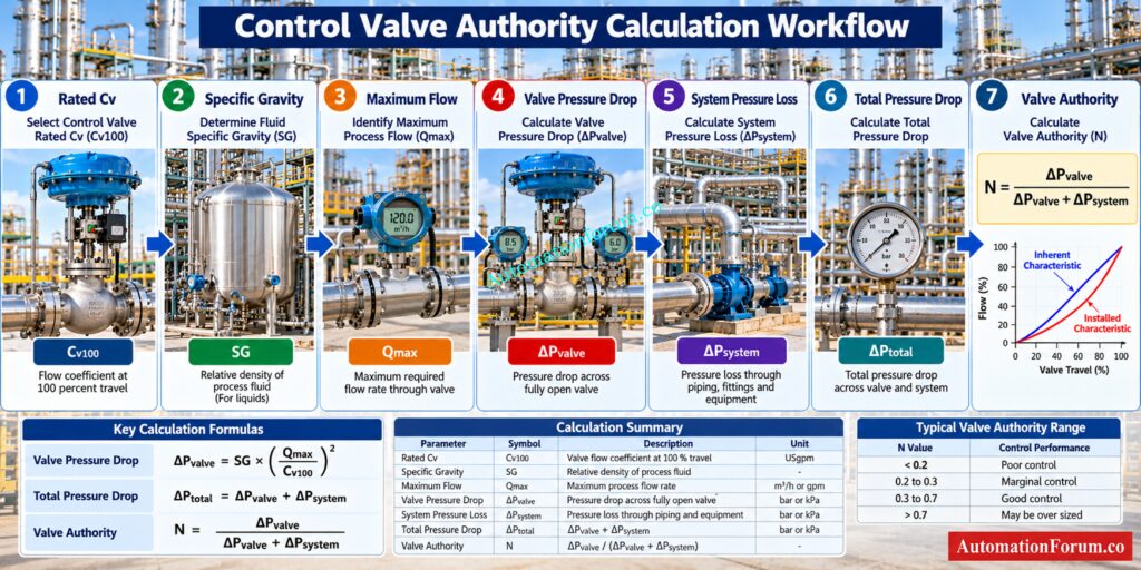
The primary calculation is:
N = ΔPvalve / (ΔPvalve + ΔPsystem)
The total pressure drop is:
ΔPtotal = ΔPvalve + ΔPsystem
When valve pressure drop is estimated from Cv:
ΔPvalve = SG × (Qmax / Cv100)²
The calculator then evaluates the installed flow using:
Q = Cv(h) × √(ΔPvalve / SG)
The system pressure loss is represented as proportional to the square of flow.
The calculator therefore solves the interaction between valve capacity and system resistance rather than simply plotting the valve manufacturer’s inherent characteristic.
Inherent Versus Installed Control Valve Characteristics
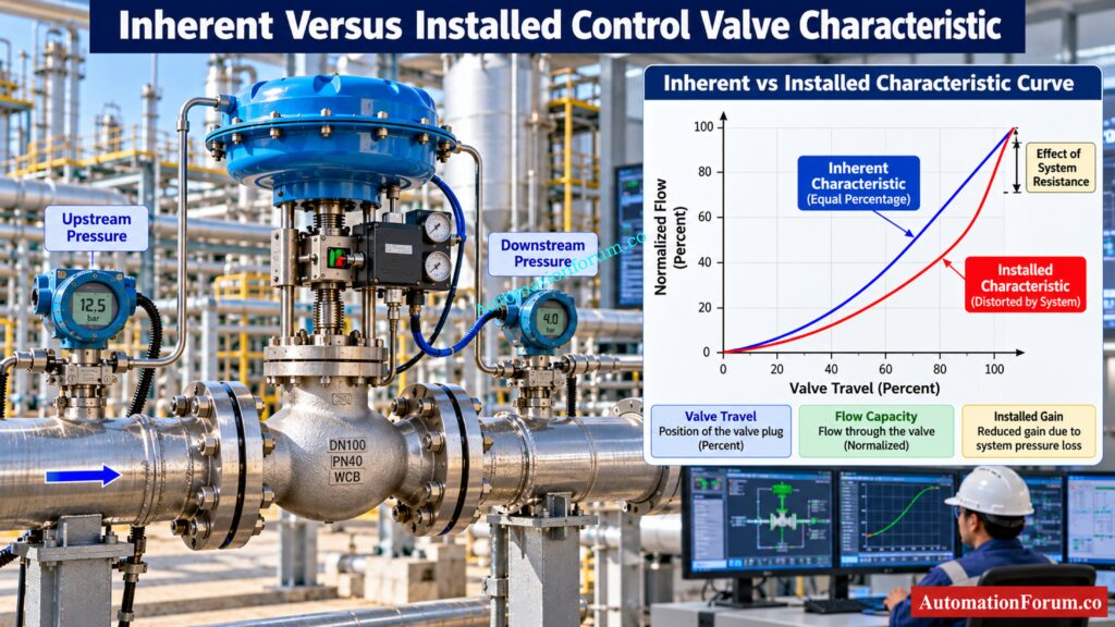
The inherent characteristic represents the valve response when the pressure drop across the valve is held constant.
The installed characteristic represents the actual response after the valve is connected to the process system.
This difference is critical for control engineers.
As flow increases, system pressure loss increases. This reduces the pressure available across the control valve. Consequently, the actual flow response can become substantially different from the theoretical inherent characteristic.
The calculator displays both characteristics so the engineer can visually assess the amount of installed distortion.
Equal percentage trim is particularly important in this context because its inherent response can compensate for the nonlinear pressure distribution created by system resistance. The correct trim choice nevertheless depends on the complete process application.
Control Valve Inherent Gain and Installed Gain
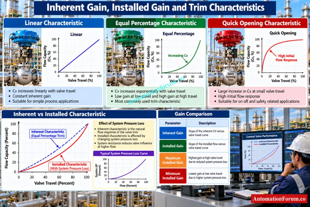
The calculator also evaluates gain.
Inherent gain represents the change in normalized valve capacity with valve travel under the inherent characteristic.
Installed gain represents the change in normalized flow with valve travel after system resistance is included.
At fifty percent travel, the calculator reports inherent gain and installed gain. It also reports the maximum and minimum installed gain across the evaluated travel range.
This information is useful because a large variation in installed gain indicates that the process does not respond uniformly throughout the valve travel range.
For control loop engineering, this can make tuning more difficult because the effective process response changes as the valve moves.
Detect Dangerous Cavitation Before It Damages Your Control Valve: Control Valve Cavitation Calculator
Control Valve Authority Calculation Example
Consider a liquid process application with the following design data:
| Parameter | Value |
| Rated Cv | 250 |
| Specific Gravity | 1.0 |
| Maximum Design Flow | 500 gpm |
| Line Loss at Maximum Flow | 20 psi |
| Entered Valve Pressure Drop | 0 psi |
| Trim Characteristic | Linear |
Because the valve pressure drop is not entered, the calculator estimates it as:
ΔPvalve = SG × (Qmax / Cv)²
ΔPvalve = 1 × (500 / 250)²
ΔPvalve = 4 psi
The total pressure drop becomes:
ΔPtotal = 4 + 20
ΔPtotal = 24 psi
N = 4 / 24
N = 0.167
The valve accounts for approximately 16.7 percent of the total pressure drop.
The estimated hydraulic power associated with the valve pressure loss is approximately 4.95 hp using the calculator’s internal power relationship.
From an engineering perspective, the result indicates that system resistance is much greater than valve resistance. The engineer should therefore review the selected Cv, available valve pressure drop, process operating range and installed characteristic before finalizing the control valve selection.
Refer the below link for the Control Valve Leakage Calculator
What is a Good Control Valve Authority?
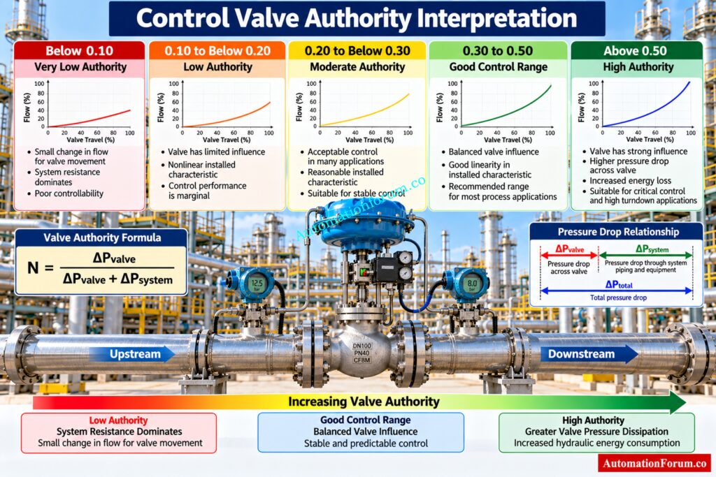
However, this should not be presented as a universal acceptance criterion for every control valve application. The process operating range, valve sizing, pump characteristics and control objective must also be considered.
Prevent Insufficient Actuator Torque From Causing Valve Failure: Control Valve Actuator Failure Due to Valve Torque
Control valve Authority interpretation table
| Valve Authority N | Engineering Interpretation |
| Below 0.10 | Very low authority and strong system influence |
| 0.10 to below 0.20 | Low authority and significant installed characteristic influence |
| 0.20 to below 0.30 | Moderate authority requiring installed characteristic review |
| 0.30 to 0.50 | Good control range according to the calculator |
| Above 0.50 | High valve influence with greater pressure dissipation |
Fix AUTO Mode Instability Before It Disrupts Process Control: Why Control Valve Hunts in AUTO but Runs Smoothly in MANUAL
How to Use the Control Valve Authority Calculator
Step 1: Collect Control Valve and Process Data
Obtain the maximum design flow, liquid specific gravity, piping pressure loss and available control valve data from the process and mechanical design documents.
Step 2: Enter Rated Cv
Enter the rated Cv at full valve opening from the selected valve data.
Step 3: Select the Valve Trim Characteristic
Select Linear, Equal Percentage or Quick Opening according to the proposed valve trim.
Step 4: Enter System Line Loss
Enter the line pressure loss at maximum design flow excluding the control valve.
Size Your Actuator Correctly Before Torque Problems Appear: Valve Actuator Sizing Calculator – Complete Engineering Guide for Torque, Safety Factor & Gear Ratio Selection
Step 5: Enter Valve Pressure Drop
Enter the known valve pressure drop. If it is unknown, leave the value at zero so the calculator estimates it from Cv, flow and specific gravity.
Step 6: Calculate Valve Authority
Step 7: Review Installed Flow Characteristic
Compare the inherent and installed curves and review the installed gain values.
Calculate Instrument Air Demand Before Pneumatic System Design: Air Consumption Calculator for Pneumatic Control Valves, Actuators and Instrument Air System Sizing
Step 8: Make the Engineering Decision
Control Valve Authority Applications in Process Industries
- In refineries and petrochemical plants, the calculation can be used when reviewing process control valves on cooling water, process liquid and utility systems.
- In oil and gas facilities, it can support control valve selection where pumps, piping and process equipment contribute significant pressure loss.
- In chemical plants, the analysis can help engineers understand why a correctly sized valve may still produce poor installed control.
- The same approach can support EPC design reviews, control valve procurement evaluations, commissioning investigations and plant troubleshooting.
Find The Real Cause Behind Persistent Valve Hunting: Control Valve Hunting Due to PID Controller: Causes, Effects, Root Analysis and Complete Troubleshooting Guide for Industrial Process Control Systems
Control Valve Authority Troubleshooting
A process engineer may encounter a valve that operates smoothly near one portion of its travel but becomes excessively sensitive or ineffective elsewhere.
If system resistance is high compared with valve pressure drop, the installed characteristic can differ significantly from the inherent characteristic.
If excessive pressure loss occurs across the valve, the opposite problem can arise. The valve may provide strong control influence but consume more hydraulic energy.
The calculator helps separate these effects by reporting valve pressure drop, system pressure drop, total pressure drop and installed gain.
Restore Valve Response Before Production Control Is Affected: Control Valve Not Responding: Troubleshooting Guide
Control Valve Authority Troubleshooting Table
| Plant Observation | Possible Authority Related Cause | What to Review |
| Valve has little control influence | Low valve authority | Valve pressure drop and system resistance |
| Valve is very sensitive at part travel | Installed gain variation | Installed characteristic |
| Valve appears oversized | Excessive Cv | Actual operating flow and valve pressure drop |
| High pressure loss across valve | High authority | Valve pressure drop and hydraulic energy |
| Control response changes with valve position | Variable installed gain | Inherent and installed characteristics |
| Process control remains poor after tuning | Valve characteristic distortion | Authority and installed gain |
Choose The Right Sizing Software For Better Valve Engineering: Top 10 Control Valve Sizing Software Used in Process Industries
Control Valve Authority Design Considerations
- The engineer should verify maximum flow, minimum operating flow, valve Cv, process fluid specific gravity, piping resistance and valve pressure drop.
- The selected trim characteristic should also be considered because the installed characteristic depends on both valve behavior and system resistance.
- Pump operating conditions are important when significant pressure loss occurs across the control valve because valve pressure loss directly affects hydraulic energy consumption.
- For final valve selection, manufacturer Cv data and project process conditions should always take precedence over an online preliminary calculation.
Select Reliable On Off Valves Before EPC Procurement: ON OFF Control Valve Type Selection Procedure for EPC Engineering
Control Valve Engineering Best Practices
- Use the calculator during conceptual and detailed engineering to compare alternative valve selections.
- During procurement, verify that the vendor supplied Cv and trim characteristic correspond to the valve being offered.
- During commissioning, compare calculated expectations with actual measured process behavior where reliable field pressure and flow data are available.
- During troubleshooting, do not immediately change PID tuning when the installed valve characteristic has not been evaluated. A valve with strongly varying installed gain can create a control problem that cannot be solved by tuning alone.
- The calculator should be treated as an engineering analysis aid rather than a replacement for certified valve sizing.
Protect Control Valves Against Severe Process Conditions: Control Valve Selection and Recommended Practices for Harsh Process Conditions
Control Valve Authority Standards and Engineering References
Get Valve Sizing Right Before Performance Problems Start: How to Properly Size Control Valves for Maximum Efficiency?
Control Valve Authority Calculator Limitations
- The calculator uses a simplified liquid flow relationship and models system pressure loss as proportional to the square of flow.
- It does not replace a complete control valve sizing calculation for complex services.
- The calculator does not perform a complete compressible flow sizing analysis for gas or steam service. It also does not independently evaluate cavitation, flashing, viscosity correction, piping geometry factors or detailed manufacturer specific valve coefficients.
- Final engineering verification should therefore use the applicable project process data, certified valve manufacturer information and the appropriate sizing methodology.
Verify Actual Cv Before Making Critical Sizing Decisions: Why Measuring Control Valve Cv is Essential for Proper Valve Sizing ?
Frequently Asked Questions About Control Valve Authority
What is control valve authority?
How do I calculate valve authority?
What is a good control valve authority?
Calibrate Your Control Valve For Reliable Process Response: Control Valve Calibration Procedure
How does Cv affect valve authority?
What causes low control valve authority?
Why is control valve authority important?
Predict Valve Noise Before It Becomes A Plant Issue: Control Valve Noise Prediction Calculator – IEC 60534 Based Engineering Tool
What is the difference between inherent and installed valve characteristics?
The inherent characteristic describes valve behavior at a constant pressure drop across the valve.
The installed characteristic includes the effect of changing system pressure loss during actual operation.
What are the three common control valve flow characteristics?
The three characteristics used by the calculator are Linear, Equal Percentage and Quick Opening.
They define how the valve flow coefficient changes as the valve moves through its travel range.
How do I calculate control valve Cv?
For liquid service, Cv can be determined from flow rate, pressure drop and fluid specific gravity.
The calculator uses the relationship ΔPvalve = SG × (Qmax / Cv100)² to estimate valve pressure drop.
How is flow calculated through an equal percentage control valve?
The calculator represents equal percentage Cv using Cv(h) = Cv × 50^(h − 1), where h represents normalized travel.
Installed flow is then evaluated using valve capacity, pressure drop and specific gravity while considering system resistance.
Can low valve authority affect control loop performance?
Can a control valve have too much authority?
Determine Required Valve Travel Before Final Control Selection: Control Valve Stroke Length Calculator
Conclusion: Control Valve Authority for Better Valve Selection and Process Control
For instrumentation and control engineers, the important point is that a valve should be evaluated as part of the complete process system. Rated Cv alone does not describe how the valve will behave after installation.
Refer the below link for the Top Essential Control Valve Calculators and Excel Tools for Instrumentation Engineers
