
- Vibration Transmitter Calculation and Industrial Machinery Monitoring
- What Is a Vibration Transmitter and How Does It Work?
- Why Is Vibration Severity Assessment Important for Rotating Equipment?
- Vibration Transmitter Calculator Input Parameters and Measurement Units
- Vibration Calculation Formulas for Industrial Machinery
- Practical Vibration Transmitter Calculation Examples
- How to Use the Vibration Transmitter and ISO 20816 Severity Calculator
- Industrial Applications of Vibration Transmitter Monitoring
- Common Vibration Transmitter Problems and Troubleshooting Methods
- Vibration Transmitter Selection and Industrial Engineering Design Considerations
- ISO 20816, ISO 10816 and API 670 Standards for Machinery Vibration Monitoring
- Limitations of Vibration Severity and Transmitter Loop Calculations
- Frequently Asked Questions About Vibration Transmitter Calculation
- Conclusion: Improving Machinery Reliability Through Vibration Monitoring
Vibration Transmitter & ISO 10816 Severity Calculator
Machine Vibration Signal Path
Try a Typical Operating Condition
1. Enter the Vibration Reading
2. Select the Assessment Basis
3. Configure the Transmitter Signal Loop
Calculated Condition and Instrument Loop Review
Severity Limit Band Visualization
4–20 mA Current Loop Electrical Diagnostics
Severity & Loop Warnings
How the Calculator Reaches Its Results
Calculation Summary
Formulas, Assumptions and Design Guidance
1. Vibration parameter conversion
Peak values are converted to RMS using the entered crest factor. Peak-to-peak displacement is converted to peak and then RMS. These relationships assume a sinusoidal component at the selected frequency.
2. 4–20 mA transmitter scaling
3. Cable loop resistance and voltage headroom
4. Severity zone interpretation
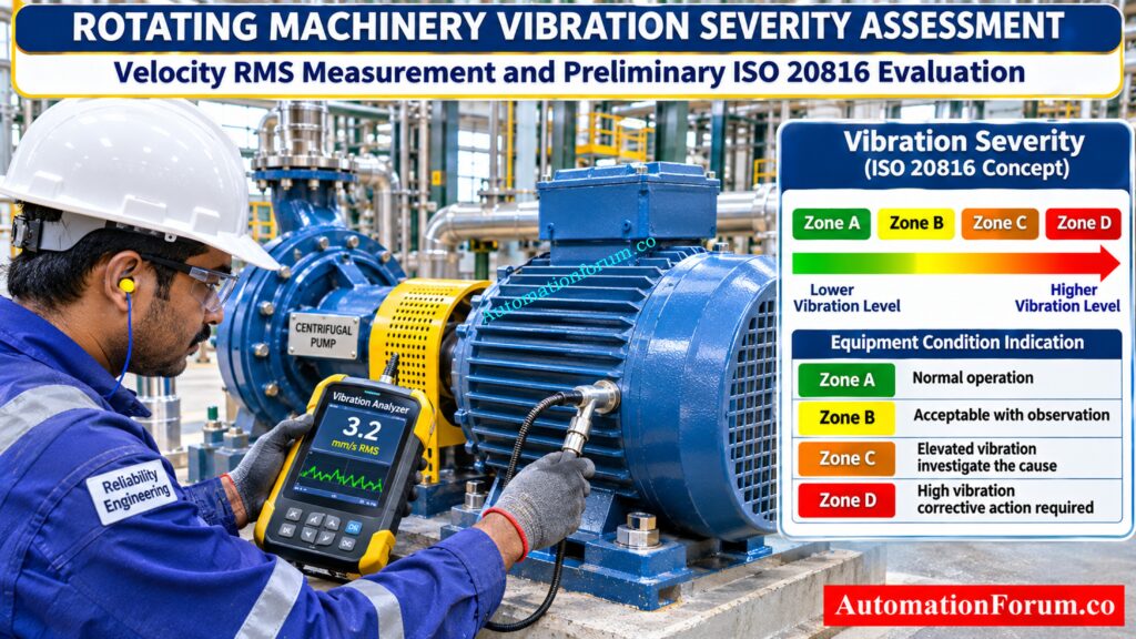
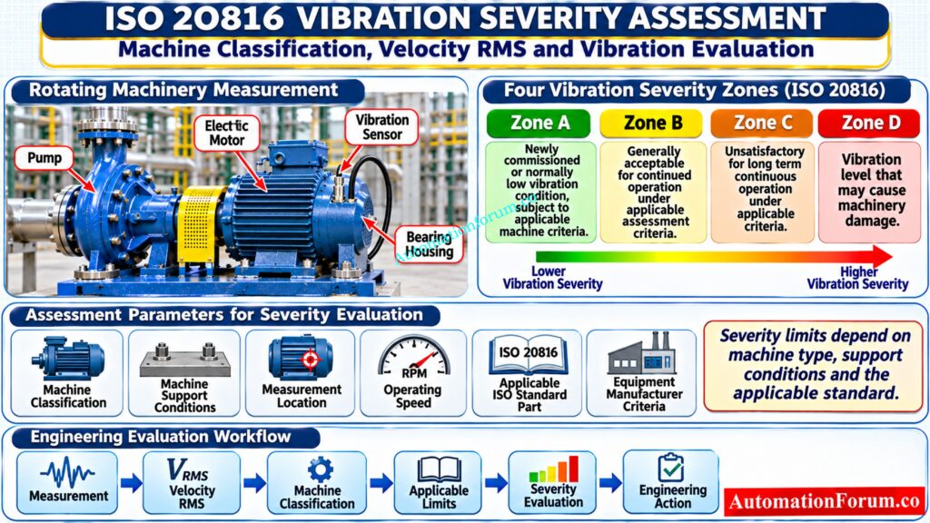
Zone A generally indicates vibration typical of newly commissioned machinery. Zone B is generally acceptable for unrestricted long-term operation. Zone C indicates unsatisfactory vibration requiring planned corrective action. Zone D indicates unacceptable vibration and requires prompt engineering assessment. Actual limits depend on machine category, support, measurement location and the applicable standard.
5. Engineering limitations
This calculator is an engineering screening aid. It does not replace the full ISO or API standards, machine-specific acceptance criteria, OEM documentation, vibration spectrum analysis, protection-system cause-and-effect review, or a site-approved alarm and trip philosophy. Do not use its output alone to set machinery shutdown limits.
Engineering calculator for preliminary design checks · AutomationForum.co
Vibration Transmitter Calculation and Industrial Machinery Monitoring
Vibration monitoring is an important part of machinery protection and predictive maintenance in industrial plants. Pumps, compressors, motors, turbines and industrial fans generate mechanical vibration during operation. Changes in vibration levels can indicate developing mechanical problems such as bearing damage, shaft misalignment, rotor imbalance and looseness.
A Vibration Transmitter Calculator helps instrumentation and reliability engineers convert different vibration measurements into velocity RMS, evaluate preliminary vibration severity, calculate transmitter output current and verify the electrical performance of a 4 to 20 mA signal loop.
These calculations are useful during instrument selection, engineering design, commissioning and machinery condition monitoring.
What Is a Vibration Transmitter and How Does It Work?
Vibration Sensor and Transmitter Working Principle
A vibration transmitter measures mechanical vibration from rotating equipment and converts the measured signal into a standardized electrical output.
Depending on the instrument design, the measurement may originate from an accelerometer, velocity sensor or proximity probe.
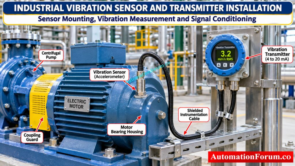
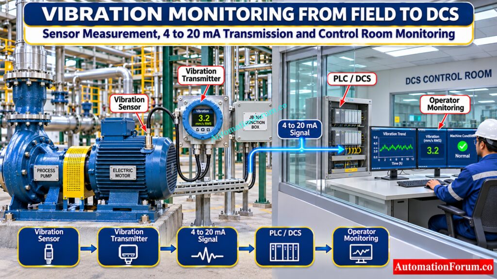
Vibration Monitoring Signal Flow from Sensor to PLC and DCS
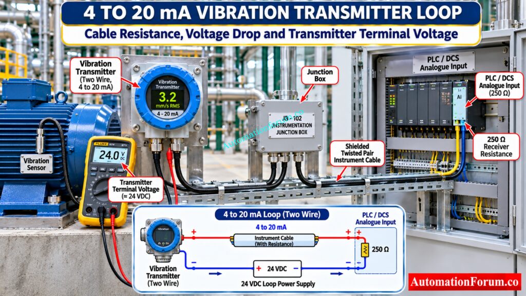
A typical industrial vibration monitoring arrangement follows this signal path:
- The vibration sensor detects mechanical movement.
- The transmitter processes the measurement.
- The vibration value is converted into a proportional 4 to 20 mA signal.
- The PLC or DCS receives the signal through an analogue input channel.
- Operators monitor vibration conditions and associated alarms.
This arrangement allows continuous monitoring of rotating equipment from the control room.
Test your troubleshooting skills before the next plant failure: Troubleshooting Bently Nevada 3500 Series Vibration Monitoring System Quiz for Process Industries
Why Is Vibration Severity Assessment Important for Rotating Equipment?
Vibration severity assessment helps engineers understand whether machinery is operating within its acceptable vibration range.
Increasing vibration can be associated with several mechanical conditions.
| Mechanical problem | Possible vibration indication |
| Rotor imbalance | Increased vibration at running speed |
| Shaft misalignment | Increased vibration at running speed and associated harmonics |
| Bearing deterioration | Increased vibration and high frequency components |
| Mechanical looseness | Harmonics and irregular vibration |
| Resonance | Excessive vibration near a natural frequency |
Vibration measurements should be evaluated alongside operating conditions, vibration trends and frequency spectrum information. A single overall reading cannot independently identify every mechanical fault.
Refer the below link for the Functional Testing of Bently Nevada Vibration Probes
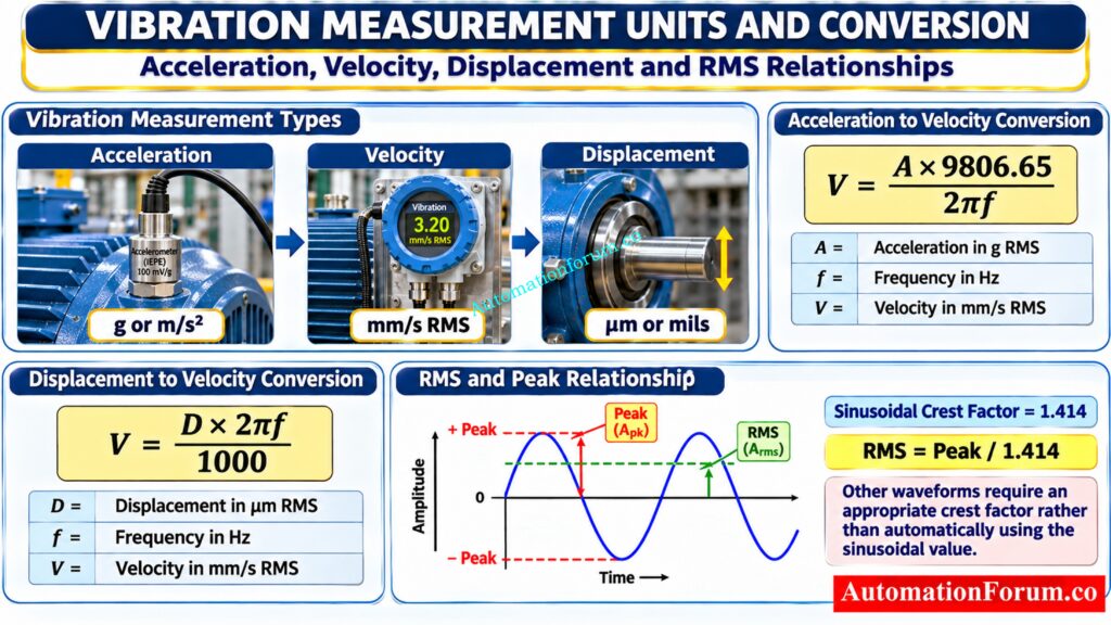
Vibration Transmitter Calculator Input Parameters and Measurement Units
Vibration Measurement Units: Velocity, Acceleration and Displacement
The calculator accepts vibration measurements in different units:
- Velocity in mm/s RMS or peak.
- Velocity in inches per second RMS or peak.
- Acceleration in g or m/s².
- Displacement in micrometres RMS, peak or peak to peak.
- Displacement in mils peak to peak.
Selecting the correct measurement unit is essential because an incorrect selection produces an incorrect converted vibration value.
Challenge your sensor knowledge with these advanced questions: Advanced Vibration Sensors and Probes Quiz
Vibration Frequency and Machine Running Speed in RPM
Frequency is required when converting acceleration or displacement into velocity.
The machine speed in RPM is provided as reference information. The entered frequency is used directly in the conversion calculation.
For example, a machine operating at 1500 RPM has a rotational frequency of 25 Hz.
Convert vibration readings accurately before making critical decisions: Vibration Unit Conversion Calculator
Waveform Crest Factor and RMS Conversion
Crest factor represents the ratio between peak amplitude and RMS amplitude.
For a sinusoidal waveform:
Crest Factor = 1.414
The calculator provides sinusoidal and impact waveform presets, together with a custom setting.
ISO 20816 Vibration Severity Assessment Parameters
The calculator provides assessment selections for ISO 20816 and ISO 10816 references, pump categories, machine groups and foundation conditions.
It also allows engineers to enter custom Zone A, B, C and D boundaries.
These limits must be checked against the applicable standard and equipment manufacturer requirements.
Discover why signal polarity matters in reliable monitoring: Why we use Negative Voltage in Vibration Measurement ?
Vibration Transmitter Range, Cable Resistance and Loop Supply Voltage
The electrical calculation requires:
- Transmitter full scale in mm/s RMS.
- Loop supply voltage.
- Minimum transmitter operating voltage.
- PLC or DCS input resistance.
- One way cable distance.
- Conductor size or resistance.
- Cable ambient temperature.
These values determine whether sufficient voltage reaches the transmitter at maximum loop current.
Protect critical equipment from damaging mechanical vibration: What is vibration isolation? Why vibration isolation is needed ?
Vibration Calculation Formulas for Industrial Machinery
Acceleration to Velocity RMS Conversion Formula
For acceleration measured in g RMS:
V = (A × 9806.65) / (2πf)
Where:
V = Velocity in mm/s RMS
A = Acceleration in g RMS
f = Frequency in Hz
For acceleration measured in m/s² RMS:
V = (A × 1000) / (2πf)
Displacement to Velocity RMS Conversion Formula
For displacement measured in micrometres RMS:
V = (D × 2πf) / 1000
Where:
D = Displacement in micrometres RMS
f = Frequency in Hz
For peak measurements, the calculator uses the entered crest factor to obtain RMS values.
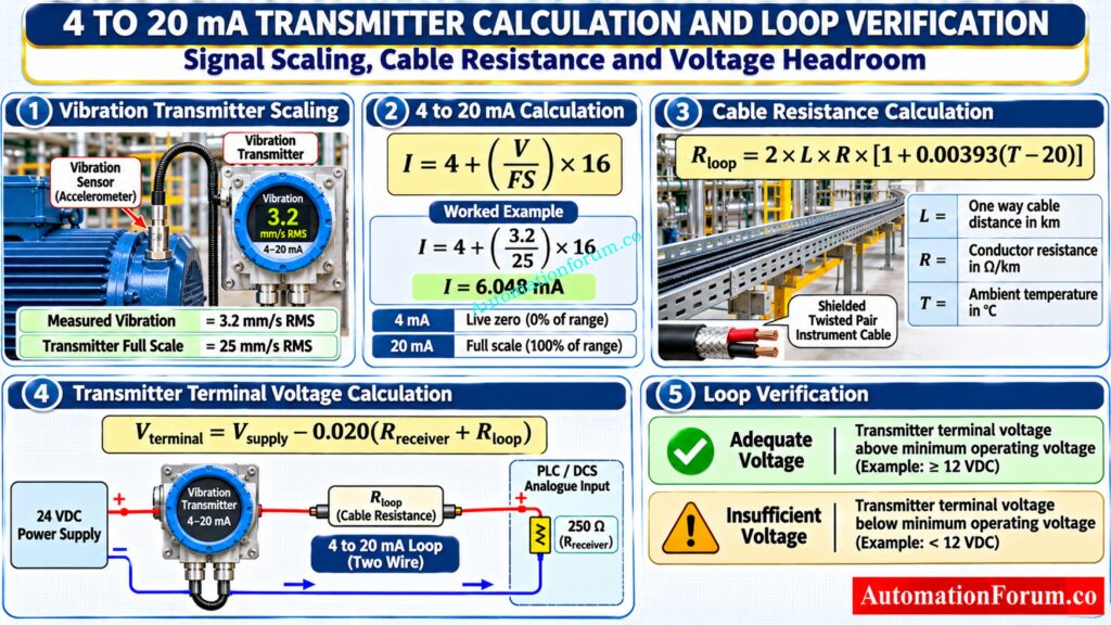
Vibration Transmitter 4 to 20 mA Output Calculation Formula
The transmitter output is calculated using:
I = 4 + (V / FS) × 16
Where:
I = Output current in mA
V = Calculated vibration velocity in mm/s RMS
FS = Transmitter full scale in mm/s RMS
Instrument Cable Resistance and Voltage Drop Calculation
The calculator estimates two wire cable resistance using:
Rloop = 2 × L × R × [1 + 0.00393 × (T − 20)]
Where:
L = One way cable distance in kilometres
R = Conductor resistance in ohms per kilometre
T = Ambient temperature in °C
Transmitter terminal voltage is calculated as:
Vterminal = Vsupply − 0.020 × (Rreceiver + Rloop)
The calculation checks whether the remaining voltage meets the transmitter minimum operating voltage at 20 mA.
Get calibration steps right before instruments enter service: Instrument Calibration Procedures
Practical Vibration Transmitter Calculation Examples
Example 1: Vibration Severity and 4 to 20 mA Calculation for a Centrifugal Pump
Consider a centrifugal pump operating in a process plant.
Given parameters:
| Parameter | Value |
| Measured vibration | 3.2 mm/s RMS |
| Transmitter full scale | 25 mm/s |
| Supply voltage | 24 VDC |
| Receiver resistance | 250 Ω |
| Cable distance | 500 m |
| Conductor resistance | 53 Ω/km |
| Ambient temperature | 45°C |
| Minimum transmitter voltage | 12 V |
Step 1: Determine vibration severity
Using the entered boundaries of 2.3, 4.5 and 7.1 mm/s:
3.2 mm/s falls within Zone B.
Step 2: Calculate transmitter output
I = 4 + (3.2 / 25) × 16
I = 6.048 mA
Step 3: Calculate cable resistance
Rloop = 2 × 0.5 × 53 × [1 + 0.00393 × (45 − 20)]
Rloop = 58.21 Ω
Step 4: Calculate transmitter terminal voltage
Vterminal = 24 − 0.020 × (250 + 58.21)
Vterminal = 17.84 V
Engineering interpretation: The calculated voltage exceeds the minimum operating requirement of 12 V. The electrical loop has approximately 5.84 V of voltage margin.
Refer the below link for the GAP voltage of Bently Nevada Vibration Probe
https://automationforum.co/gap-voltage-of-bently-nevada-vibration-probe/
Example 2: High Vibration and Cable Voltage Drop Calculation for Industrial Machinery
Consider an industrial machine with increasing vibration and a long instrument cable.
Given parameters:
| Parameter | Value |
| Vibration velocity | 8 mm/s RMS |
| Full scale | 25 mm/s |
| Cable distance | 2000 m |
| Conductor resistance | 84.2 Ω/km |
| Ambient temperature | 60°C |
| Supply voltage | 24 VDC |
| Receiver resistance | 250 Ω |
Step 1: Determine severity
Using the same boundaries, 8 mm/s falls within Zone D.
Step 2: Calculate transmitter current
I = 4 + (8 / 25) × 16
I = 9.12 mA
Step 3: Calculate cable resistance
Rloop = 2 × 2 × 84.2 × [1 + 0.00393 × 40]
Rloop = 389.74 Ω
Step 4: Verify terminal voltage
Vterminal = 24 − 0.020 × (250 + 389.74)
Vterminal = 11.21 V
The available voltage is below the required 12 V.
Engineering interpretation: Two problems require investigation. The machinery vibration exceeds the entered severity boundary, and the instrument loop has insufficient voltage headroom at 20 mA.
Prevent missing documents from delaying critical commissioning activities: What Is an Instrument Loop Folder? Documents, Preparation and Commissioning Guide
How to Use the Vibration Transmitter and ISO 20816 Severity Calculator
- Enter the measured vibration value and select its correct unit.
- Enter the frequency associated with the measured vibration.
- Select the appropriate crest factor.
- Choose the assessment reference and machine conditions.
- Verify the vibration severity boundaries.
- Enter the transmitter full scale and electrical supply details.
- Provide cable length, conductor resistance and ambient temperature.
- Select Calculate Severity and Verify Loop.
The results display calculated velocity RMS, severity zone, transmitter output current, cable resistance, terminal voltage and electrical loop status.
Engineers can also download a calculation report or print the results as a PDF.
Speed up engineering deliverables with smarter digital workflows: Instrumentation and Control Detailed Engineering Software Tools: Complete Guide for EPC Projects
Industrial Applications of Vibration Transmitter Monitoring
Vibration Transmitter Selection During EPC Instrumentation Design
During detailed engineering, instrumentation engineers can use vibration calculations to review transmitter ranges, analogue signal scaling, cable schedules and power supply requirements.
The instrument datasheet, equipment vendor documentation and instrument loop diagram should be reviewed before finalizing the design.
Vibration Monitoring During Installation and Commissioning
During commissioning, engineers should verify sensor installation, transmitter configuration, signal scaling and DCS indication.
A field measurement should be compared with the control system reading to identify incorrect scaling or signal transmission problems.
Vibration Condition Monitoring in Plant Operations
Maintenance engineers can monitor vibration trends to identify deterioration before machinery failure.
Abnormal readings should be investigated using vibration analysis, bearing inspection and operating condition checks.
Eliminate manual P&ID data work and reduce errors: Comparison of Top Automated Tools for Instrument Index Generation from P&IDs in EPC Engineering
Common Vibration Transmitter Problems and Troubleshooting Methods
| Problem | Possible cause | Recommended check |
| Incorrect vibration indication | Wrong transmitter range | Verify configuration and calibration |
| High vibration reading | Imbalance or misalignment | Perform vibration spectrum analysis |
| Unstable 4 to 20 mA signal | Loose termination or electrical interference | Inspect wiring and grounding |
| Low transmitter voltage | Excessive cable resistance | Check voltage drop and loop load |
| Incorrect severity classification | Wrong measurement location or threshold | Verify assessment criteria |
| Signal exceeds 20 mA | Measurement exceeds configured range | Check transmitter overrange behaviour |
Choose the right protection barrier before approving field wiring: Intrinsic Safety Barrier Selection Procedure for Instrumentation Engineers
Vibration Transmitter Selection and Industrial Engineering Design Considerations
Before selecting or commissioning a vibration transmitter, engineers should verify the following:
- Confirm whether the application requires casing vibration or relative shaft vibration measurement.
- Select a sensor suitable for the machine speed and measurement frequency.
- Verify transmitter measurement range and output scaling.
- Check the electrical load and cable resistance.
- Consider barriers, isolators and other loop components when checking voltage headroom.
- Confirm measurement location and mounting arrangement.
- Verify alarm settings against approved machinery protection documentation.
- Maintain baseline vibration readings for future comparison.
Practical engineering recommendations
| Engineering activity | Recommended verification |
| Instrument design | Confirm sensor type, measurement range and transmitter output |
| EPC engineering | Review instrument datasheet, loop diagram and cable schedule |
| Procurement | Verify transmitter specifications and OEM compatibility |
| Installation | Check sensor mounting, cable routing and grounding |
| Commissioning | Verify calibration, 4 to 20 mA scaling and DCS indication |
| Maintenance | Compare vibration trends and investigate abnormal readings |
| Machinery protection | Verify alarm and trip settings against approved documentation |
Resolve loop check failures before startup delays escalate: Common Instrument Loop Check Problems During Startup
ISO 20816, ISO 10816 and API 670 Standards for Machinery Vibration Monitoring
ISO 20816 provides guidance for measuring and evaluating machine vibration. ISO 20816 Part 3 covers specified industrial machinery, while rotodynamic pump assessment requires attention to the applicable pump specific standard.
ISO 10816 Part 7 remains an important published reference for industrial rotodynamic pumps. Its successor, ISO 20816 Part 7, is under development.
API 670 specifies requirements for machinery protection systems, including vibration monitoring hardware, installation, documentation and testing.
These standards have different scopes. Selecting a standard and entering numerical thresholds into the calculator does not establish compliance.
Prevent grounding mistakes that compromise sensitive instrument signals: Where Should You Terminate Cable Shields in Instrumentation and Control Systems?
Limitations of Vibration Severity and Transmitter Loop Calculations
This calculator is intended for preliminary engineering screening.
Acceleration and displacement conversions assume a sinusoidal component at the entered frequency. A single frequency calculation cannot accurately represent complex broadband vibration.
The severity zones depend on user entered boundaries. The calculator does not perform complete ISO machine classification or vibration spectrum analysis.
The electrical loop calculation assumes a two wire loop, copper conductor temperature correction and a constant 20 mA for voltage headroom assessment. Additional components must be included in a detailed loop design.
Never use the calculated results alone to establish machinery shutdown settings or override an approved protection system.
Improve measurement confidence with disciplined temperature sensor checks: RTD Calibration Procedure: 8 Steps for Accurate Calibration
Frequently Asked Questions About Vibration Transmitter Calculation
What is a vibration transmitter calculator?
A vibration transmitter calculator converts vibration measurements into velocity RMS, evaluates vibration severity and calculates the corresponding 4 to 20 mA output. It also helps engineers verify cable resistance, voltage drop and transmitter operating voltage.
How do you convert acceleration into vibration velocity?
For a sinusoidal vibration signal, velocity is calculated by dividing acceleration by angular frequency. The result can be expressed in mm/s RMS using the appropriate unit conversion factor.
Find smarter sizing options before finalizing valve specifications: Top 10 Control Valve Sizing Software Used in Process Industries
What is vibration velocity RMS?
Vibration velocity RMS is the root mean square value of mechanical vibration velocity over a measurement period. It is commonly used to evaluate the overall vibration severity of rotating machinery such as pumps, motors and compressors.
What is the purpose of a 4 to 20 mA vibration transmitter?
A 4 to 20 mA vibration transmitter converts measured vibration into an industrial analogue signal for PLC or DCS monitoring. This allows operators to monitor machinery conditions and configure alarms based on approved engineering limits.
Avoid isolation mistakes that put hazardous loops at risk: Understanding Zener vs Galvanic Isolation in IS Loops for 4 to 20 mA Systems
Why is cable voltage drop important in a vibration transmitter?
Cable resistance causes voltage drop in a 4 to 20 mA instrument loop, reducing the voltage available at the transmitter terminals. Excessive voltage drop can affect transmitter operation and signal reliability.
Can a vibration transmitter calculator determine machinery trip settings?
No. Machinery alarm and trip settings must be established using applicable standards, equipment manufacturer recommendations and the approved machinery protection philosophy. Calculator results should only support preliminary engineering assessment.
Select valve response characteristics that prevent costly process problems: Why Control Valve Characteristics Matter in EPC Instrumentation and Control Engineering
What happens when vibration exceeds the transmitter full scale?
When measured vibration exceeds the configured full scale, the calculated linear output becomes greater than 20 mA. Actual overrange indication depends on the transmitter design and manufacturer configuration.
Can displacement measurements be converted into vibration velocity?
Yes. Displacement can be converted into vibration velocity using the measurement frequency and the sinusoidal motion relationship. The correct RMS, peak or peak to peak conversion must be applied.
How do you calculate vibration using the vibration formula?
For sinusoidal motion, vibration velocity is calculated using V = 2πfD, where V is velocity, f is frequency and D is displacement amplitude. Use consistent units and convert the result into mm/s when required.
Organize field junction boxes for faster installation and testing: JB Grouping in Industrial Automation and Instrumentation – Complete Practical Guide for EPC, Site and Commissioning Engineers
How do you calculate a 4 to 20 mA transmitter output?
Use the formula I = 4 + [(PV − LRV) / (URV − LRV)] × 16. For a vibration transmitter with zero based scaling, this becomes I = 4 + (Measured Vibration / Full Scale) × 16 mA.
What are 1X, 2X and 3X in vibration analysis?
1X represents vibration occurring at the machine running speed, while 2X and 3X represent frequencies at two and three times running speed. These frequency components help engineers investigate imbalance, misalignment, looseness and other mechanical conditions.
What is 1 mil in vibration measurement?
One mil is equal to 0.001 inch or 25.4 micrometres. It is commonly used to express shaft displacement in rotating machinery vibration monitoring.
How much is 1G of vibration?
One G of acceleration is equal to approximately 9.80665 m/s². Its corresponding vibration velocity depends on the vibration frequency, so frequency must be known before converting acceleration into velocity.
What is the RMS value of vibration?
RMS is the square root of the mean of the squared instantaneous vibration values over a measurement period. For a pure sinusoidal waveform, RMS equals peak amplitude divided by 1.414.
Know which acceptance tests expose startup risks early: FAT vs SAT vs SIT: Three Critical Tests That Determine Whether Your Plant Is Truly Ready for Startup
Conclusion: Improving Machinery Reliability Through Vibration Monitoring
Vibration monitoring is essential for improving rotating equipment reliability and preventing unexpected machinery failures. Correct vibration conversion, severity assessment and transmitter loop verification help instrumentation and reliability engineers evaluate measurement performance and identify potential design problems.
The Vibration Transmitter Calculator brings these calculations together in one engineering tool. Use it for preliminary design checks, commissioning verification and maintenance investigations, while confirming all critical limits against applicable standards and manufacturer documentation.
Refer the below link for the Method Statement for Installation and Commissioning of Vibration Proximity Monitors for Rotating Machinery
