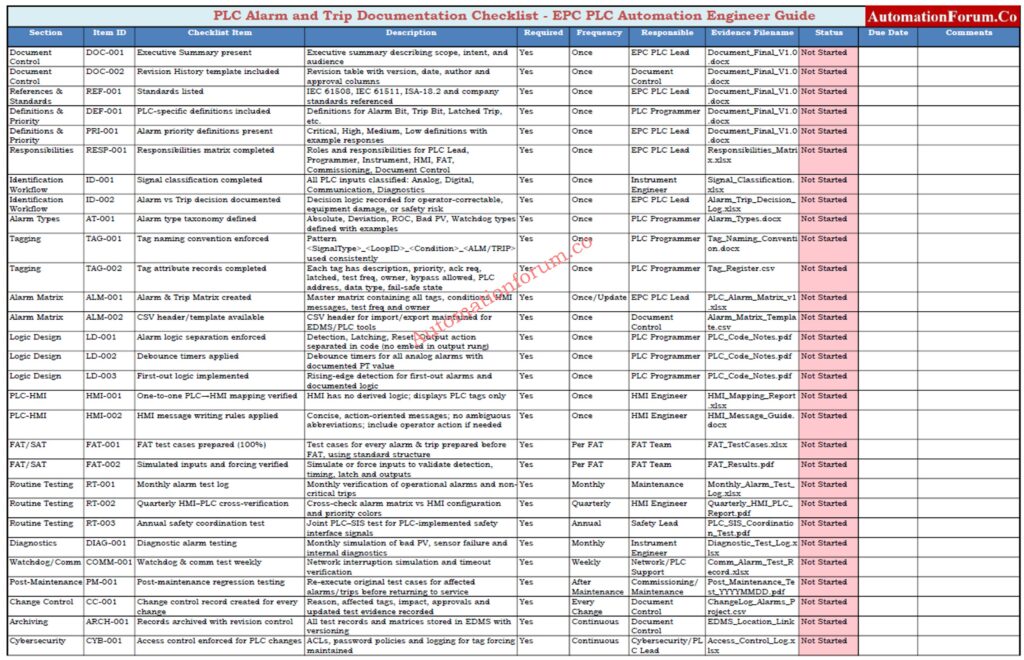
- PLC Alarm and Trip Documentation
- Purpose and Objectives of the Procedure
- Scope and Explicit Exclusions
- Applicable Standards and References
- Key Definitions and Alarm Terminology
- Alarm Priority and Severity Definitions
- Roles & Responsibilities (Responsibilities Matrix)
- Alarm & Trip Identification Workflow
- PLC Alarm and Trip Tagging Convention
- Alarm & Trip Matrix – Master Configuration and Testing Document
- PLC Alarm & Trip Logic Design Rules
- PLC Ladder / SFC Pseudocode
- PLC – HMI Alarm Mapping and Message Guidelines
- Functional Test Procedure (FAT / SAT) – Test Cases & Evidence
- Routine Testing, Diagnostics and Proof Records
- Change Control, Post-Maintenance Validation and Regression Testing
- Troubleshooting Guide and Common Faults
- EPC Handover & Close-Out Package – Deliverables Checklist
- Download: PLC Alarm & Trip Test Checklist and Templates
- Cybersecurity, Access Control and Forcing Policy
- FAQ – Common Questions on PLC Alarms and Trips
PLC Alarm and Trip Documentation
NFPA 72 Explained Finally: Method Statement for Addressable Fire Alarm System Installation, Testing and Commissioning as per NFPA 72
Purpose and Objectives of the Procedure
The purpose of this document is to establish a standardized PLC alarm and trip documentation procedure that:
- Prevents nuisance alarms and spurious trips
- Ensures consistent PLC-HMI alarm behavior
- Creates auditable FAT/SAT records
- Enables smooth EPC handover to operations and maintenance
Refer the below link for the Alarm & Trip Setpoint List in Instrumentation Engineering: The Most Critical Document for Plant Safety
Scope and Explicit Exclusions
This procedure applies to:
- PLC-implemented alarms (process, equipment, diagnostic)
- PLC-implemented trips and interlocks
- PLC interface signals to SIS or external protection systems
- PLC → HMI/DCS alarm mapping and acknowledgement logic
- FAT, SAT, and commissioning documentation
Explicit exclusions
- SIS logic design (IEC 61508 / 61511 calculations)
- DCS alarm management philosophy
- Operator training manuals
Stop Wrong Detector Placement: Fire Alarm Detector Coverage Calculator – Professional Excel Tool for Accurate Detector Placement
Applicable Standards and References
IEC 61508 – Functional safety of electrical, electronic, and programmable electronic systems
IEC 61511 – Functional safety for the process industry sector (SIS)
ISA-18.2 – Management of Alarm Systems for the Process Industries
Company Engineering Document Control and Alarm Philosophy Standards
PLC vendor programming and HMI configuration manuals
Most Engineers Get Alarms Wrong: Guide to Industrial Process Alarms in Control Systems: Types, Classifications, and Management Methods
Key Definitions and Alarm Terminology
| Term | PLC-Specific Meaning |
| Alarm Bit | Boolean tag generated inside PLC logic |
| Trip Bit | Boolean tag that forces output OFF or blocks operation |
| Latched Trip | Trip requiring manual reset after condition clears |
| Non-Latched Trip | Auto-reset trip when condition normalizes |
| Alarm Suppression | PLC logic disabling alarms during maintenance |
| First-Out Alarm | PLC logic identifying first initiating cause |
| Maintenance Bypass | Controlled PLC bypass with logging |
Alarm Checklist Everyone Misses: DCS Alarm Management Checklist
What are alarm, trip point, and alarm priority in DCS & PLC?
Alarm Priority and Severity Definitions
Critical: Immediate action required. Failure to respond may cause plant shutdown, equipment damage, or safety risk.
High: Prompt operator action required to prevent process upset or equipment stress.
Medium: Operator action recommended but no immediate safety or asset risk.
Low: Informational or advisory alarm for maintenance or monitoring.
HMI Alarms Done Right: Human Machine Interface Alarms (HMI Alarms)
Roles & Responsibilities (Responsibilities Matrix)
| Role | Responsibility |
| EPC PLC Lead | Alarm philosophy, logic architecture, documentation |
| PLC Programmer | Implement alarm & trip logic, comments, tag attributes |
| Instrument Engineer | Validate input range, fail states, scaling |
| HMI Engineer | Alarm banner behavior, priority colors, ack logic |
| FAT Team | Execute test cases, record deviations |
| Commissioning Engineer | SAT validation, final acceptance |
| Document Control | Revisioning and handover package |
Can You Pass This Trip?: Gas Turbine Start Interlock & Trip Test Procedure – Advanced Quiz
Alarm & Trip Identification Workflow
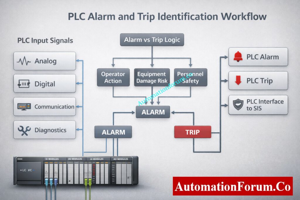
Step 1 – Signal classification (Analog, Digital, Comm, Diagnostics)
Classify every PLC input:
- Analog (process)
- Digital (status/interlock)
- Communication health
- Internal PLC diagnostics
Step 2 – Alarm vs Trip decision tree (operator, equipment, safety)
| Question | If YES | If NO |
| Can operator correct without stopping? | Alarm | Trip |
| Equipment damage risk? | Trip | Alarm |
| Personnel safety risk? | SIS or PLC-interface | Alarm |
Step 3 – Alarm type definition (Absolute, Deviation, ROC, Bad PV)
- Absolute (High / Low)
- Deviation
- Rate-of-Change
- Bad PV / Sensor failure
- Watchdog / heartbeat loss
Permissive Logic Most Ignore: Understanding Permissive Logic and Trip Interlocks in Industrial Systems
PLC Alarm and Trip Tagging Convention
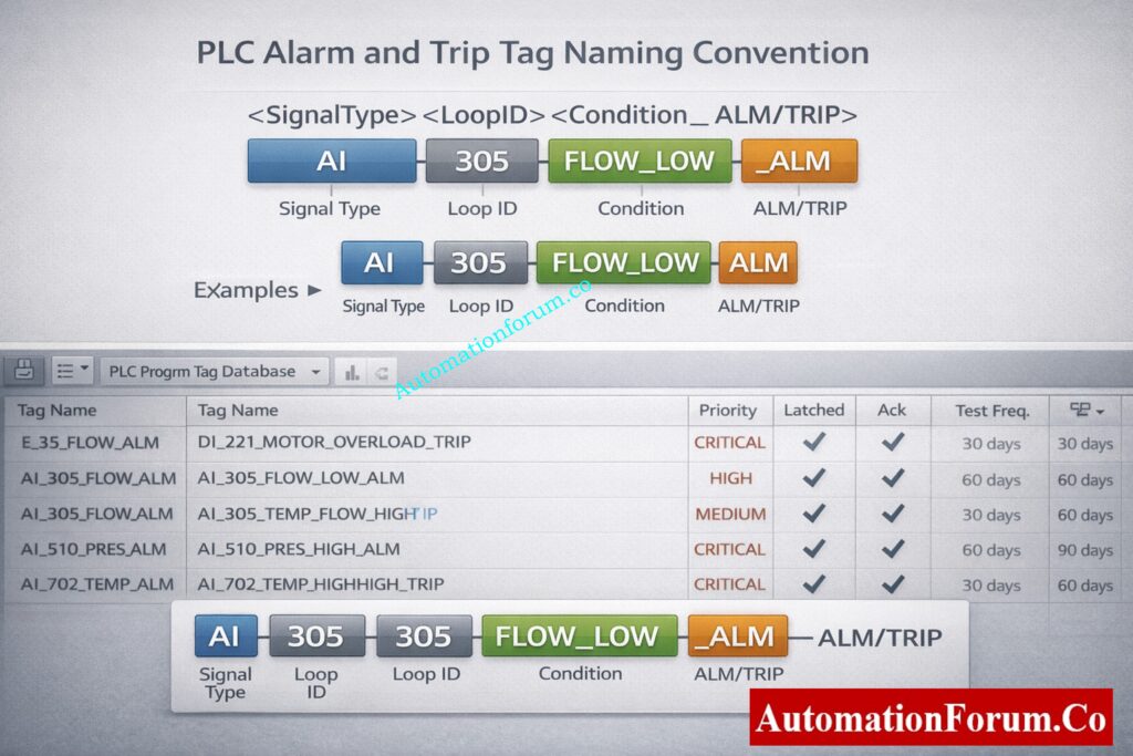
Mandatory EPC Rule:
No alarm or trip exists without a documented tag.
Naming Pattern
<SignalType>_<LoopID>_<Condition>_<ALM/TRIP>
Examples
- AI_305_FLOW_LOW_ALM
- AI_305_FLOW_LOWLOW_TRIP
- DI_410_MOTOR_TRIP_FB
- COMM_PLC1_HMI_TIMEOUT_ALM
Mandatory Tag Attributes
- Description
- Priority
- Ack Required (Yes/No)
- Latched (Yes/No)
- Test Frequency
- Owner Discipline
- Bypass Allowed (Yes/No)
Refer the below link: best Practices for PLC Tag and Address Naming Conventions
Standard Alarm and Trip Tag Attribute Record
Each PLC alarm or trip tag shall include tag name, description, priority, acknowledgement requirement, latching behavior, test frequency, owner discipline, bypass permission, PLC address, data type, fail-safe state, and engineering comments. No alarm or trip shall be accepted without a completed attribute record.
PLC Permissives Fail Here: PLC Permissive Logic Troubleshooting Procedure for Instrumentation Engineers
Alarm & Trip Matrix – Master Configuration and Testing Document
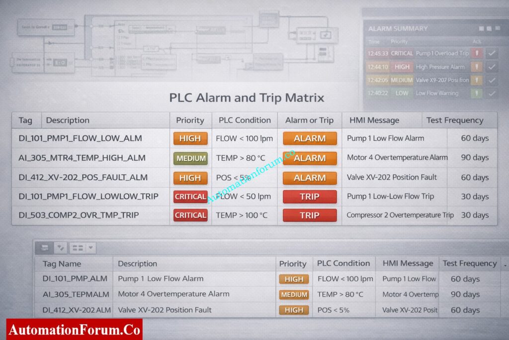
The alarm matrix is the master document for PLC alarm and trip configuration and testing.
| Tag | Description | Priority | PLC Condition (Logic) | Alarm or Trip | HMI Message | Acknowledgement Required | Test Frequency |
| PB_P101_FLW_ALM_001 | Pump P101 low flow | High | Flow < 10 percent for 15 s | Alarm | P101 LOW FLOW | Yes | Monthly |
| PB_P101_TMP_TRP_001 | Pump P101 high temperature | Critical | Temp > 90 C for 3 s | Trip | P101 OVER TEMP TRIP | No | Commissioning Annual |
| HT101_PRES_ALM_002 | Heater high pressure | Medium | Pressure > 2.0 bar for 10 s | Alarm | HT101 HIGH PRESSURE | Yes | Quarterly |
| V102_POS_ALM_003 | Control valve position fault | High | Cmd ≠ feedback for 5 s | Alarm | V102 POSITION FAULT | Yes | Monthly |
| C101_LEV_TRP_004 | Sump high high level | Critical | HH level and pump fail | Trip | C101 LEVEL HI HI | No | Monthly |
| G01_OC_TRP_005 | Generator overcurrent | Critical | Current > 120 percent | Trip | G01 OVERCURRENT TRIP | No | Annual |
| F101_VIB_ALM_006 | Filter vibration high | Low | Vibration > limit for 10 s | Alarm | F101 VIBRATION | Yes | Monthly |
The alarm and trip matrix shall be maintained as the single source of truth for all PLC alarms and trips. Any PLC logic, HMI alarm, or test case without a corresponding entry in the alarm matrix is not permitted.
Dead Zero Can Destroy Loops: Beyond Zero: Understanding the Dead Zero Problem in Industrial Analog Signals
PLC Alarm & Trip Logic Design Rules
Never embed alarm logic directly inside output rung
Always separate:
- Detection
- Latching
- Reset
- Output action
Use debounce timers for all analog alarms
Use rising-edge detection for first-out logic
Grounding Mistakes Causing Failures: Grounding and Bonding in Instrumentation and Control Systems
PLC Ladder / SFC Pseudocode
Alarm Detection
IF AI_FLOW < FLOW_LOW_SP THEN
T_FLOW_LOW(IN:=TRUE, PT:=8s)
ELSE
T_FLOW_LOW(IN:=FALSE)
END_IF
IF T_FLOW_LOW.Q THEN
FLOW_LOW_ALM := TRUE
END_IF
Trip Logic (Latched)
IF AI_FLOW < FLOW_LL_SP AND NOT BYPASS_FLOW THEN
FLOW_LL_TRIP := TRUE
END_IF
Trip Reset
IF RESET_CMD AND AI_FLOW > FLOW_LOW_SP THEN
FLOW_LL_TRIP := FALSE
END_IF
Output Interlock
IF FLOW_LL_TRIP THEN
MOTOR_RUN_CMD := FALSE
END_IF
PLC Scaling Errors Exposed: PLC Raw Count Calculator: Comparison with PLC Internal Scaling Blocks, Real-World Use Cases and Practical Benefits
PLC – HMI Alarm Mapping and Message Guidelines
- One-to-one tag mapping (no derived HMI alarms)
- HMI must not create logic-based alarms
- PLC controls:
- Priority
- Ack requirement
- Latched state
- HMI only displays and acknowledges
HMI Message Writing Rules
Alarm messages shall be short, clear, and action-oriented. Messages shall identify the equipment and condition without abbreviations that operators may misinterpret. Alarm logic shall not be implemented in the HMI. The HMI shall only display, acknowledge, and log PLC-generated alarms.
Panels Fail Without This: Running Inspection Checklist of PLC Components in Control Panels
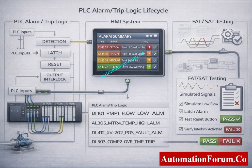
Functional Test Procedure (FAT / SAT) – Test Cases & Evidence
- Before testing, look over the approved alarm matrix.
- Check that the instruments are calibrated and that the signals are correct.
- Use calibrated sources or PLC forcing to make alarm and trip circumstances happen.
- Check the PLC’s detection time, latch behavior, and interlock logic.
- Confirm final output actions such as motor stop or valve closure.
- Verify HMI message text, priority, audible alarm, and acknowledgement behavior.
- Verify alarm logging, timestamps, and operator identification.
- Get things back to normal and check to see whether the reset works.
- Write down the results and get the witness to sign off.
Standard FAT and SAT Test Case Structure
A documented test case that includes the test case ID, tag name, objective, preconditions, test procedures, expected results, actual results, tester name, date, and witness signature must be used to test each alert and trip. Testing without written evidence is not acceptable.
This PLC Rules Industry: Which PLC is Mostly used in the Automation Industry?
Routine Testing, Diagnostics and Proof Records
| Test Phase / Item | Alarm / Trip Category | PLC Scope Covered | Minimum Test Frequency | Test Method (PLC-Focused) | Records / Evidence Required |
| Commissioning (FAT / SAT) | All alarms and all trips | All PLC alarm bitsAll PLC trip logicHMI alarm mappingAcknowledgement behaviorOutput interlocks | Mandatory (100%) | Simulate inputs / force bitsValidate PLC logic executionVerify HMI banner, priority, and message textVerify trip action and reset logic | Signed FAT/SAT test sheetsPLC_Trip_Test_Record_YYYYMMDD.pdfUpdated Alarm Matrix |
| Monthly Testing | Operational alarms & non-critical trips | Process alarmsEquipment status alarmsNon-latched trips | Monthly | Input simulation or value forcingTimer and debounce verificationHMI alarm acknowledge test | Monthly alarm test logAlarm acknowledgment verification record |
| Quarterly Testing | Medium-priority alarms & HMI verification | Medium-priority alarm logicHMI priority color codingAlarm text consistency | Quarterly | Cross-check PLC alarm matrix vs HMI configurationSimulate alarm to verify correct banner and priority | HMI-PLC cross-verification reportUpdated alarm matrix (if modified) |
| Quarterly Testing | Critical trips (PLC-implemented) | Latched trip logicInterlock logicReset permissives | Quarterly | Simulate initiating conditionVerify forced output OFFVerify trip latch and manual reset | Trip proof test recordPLC event log snapshot |
| Annual Testing | PLC-implemented safety functions (Interface to SIS) | PLC-SIS interface signalsHardwired and soft interlocksFirst-out alarms | Annually | Coordinated test with SIS team• PLC signal injection and feedback confirmation | Joint PLC-SIS test certificateSafety coordination test report |
| Diagnostic Testing | Diagnostic alarms | Sensor failure detectionBad PV / out-of-range logicInternal PLC diagnostics | Monthly | Simulate signal fault / disconnect inputVerify alarm generation and HMI indication | Diagnostic alarm test log |
| Watchdog / Communication Testing | PLC-HMI / PLC-PLC communications | Heartbeat logicCommunication timeout alarms | Weekly | Network interruption simulationTimeout value verification | • Communication alarm test record |
| Post-Maintenance Testing | Any affected alarm or trip | Modified logicReplaced instrumentsRewired I/O | Mandatory (Before Return to Service) | Re-execute original test caseVerify no regression in unrelated alarms | Post-maintenance proof test recordChange management approval |
| Configuration Change Testing | Alarm / trip logic changes | Modified PLC rungs or blocksHMI mapping changes | Every Change | Regression test of related alarmsVersion comparison | Updated alarm matrix revisionChange log entry |
Missing PLC Documents Cause Failures: PLC System Documentation Guide: Essential Records for Industrial Automation Success
Change Control, Post-Maintenance Validation and Regression Testing
Any maintenance activity affecting PLC logic, field instruments, wiring, or I/O shall require re-testing of affected alarms and trips before returning the equipment to service. Results shall be recorded and approved by commissioning or maintenance engineering.
Mandatory Documentation & Archiving Rules
- All test results must be recorded no verbal acceptance.
- Store records in document control / EDMS with revision control.
- Each record must include:
- Date & time
- PLC program version
- Tester name & signature
- Pass / fail status
- Observations & corrective actions
- Typical filenames:
- PLC_Alarm_Matrix_vX.xlsx
- PLC_Trip_Test_Record_YYYYMMDD.pdf
- PLC_Post_Maintenance_Test_YYYYMMDD.pdf
Change Control Requirements
Hot Standby Saves Shutdowns: Hot Standby in PLC Systems: Architecture, Working, and Benefits
Troubleshooting Guide and Common Faults
- Alarm not displayed on HMI: Verify PLC tag mapping, communication status, and alarm enable bits.
- Spurious alarms or trips: Check signal noise, grounding, debounce timers, and filtering.
- Alarm goes off without being acknowledged: Check the latch logic and how it handles acknowledgments.
- Intermittent alarms: Turn on event logging and get raw process information when an alert goes off.
Analog Scaling Mistakes Engineers Make: Scaling Analog Values in Industrial Automation (PLC)
EPC Handover & Close-Out Package – Deliverables Checklist
Mandatory EPC handover bundle:
- Send the signed test records and the approved alarm matrix.
- Use version control on every document.
- Keep a record of any changes to alarms or trips.
- Keep old versions for reference for auditing and maintaining.
NO vs NC – Costly Mistake: Understanding NO vs NC Contacts is key for Logic Writing in PLC Programming
Download: PLC Alarm & Trip Test Checklist and Templates
This Excel checklist gives EPC projects a disciplined and verifiable way to record, test, and hand over PLC alarms and trips. It makes sure that the PLC and HMI always work the same way, gets rid of undocumented logic, and helps with FAT, SAT, and commissioning tasks. It was made for PLC automation engineers and helps make sure that everything works right and that the EPC handover is clean.
Includes:
- Alarm identification checklist
- FAT/SAT test sheets
- Bypass & suppression log
- Revision control sheet
Download the PLC Alarm & Trip Test Checklist (automationforum.co) and join our professional forum at automationforum.co to access EPC-grade PLC templates, alarm matrices, and peer-reviewed practices.
Why 24V Prevents Failures: Why is 24 Volts Mostly used in Industrial PLC Systems?
Cybersecurity, Access Control and Forcing Policy
PLC alarms and trips should never be used instead of SIS protections. All PLC logic that has to deal with safety must be explicitly marked, written down, tested, and included into the SIS design. For safe and reliable plant operation, paperwork and testing must be done on a regular basis.
Ladder Rules You Must Follow: Top 6 Important Rules for PLC Ladder Diagram Programming
FAQ – Common Questions on PLC Alarms and Trips
What is an alarm in PLC?
A PLC alarm is a programmed condition that finds an abnormal state of equipment or process. It tells the operator to take action through HMI or DCS. Alarms can be latched or not latched, and you normally have to recognize them.
What is the alarm and trip schedule?
An alarm and trip schedule is a documented list of all PLC alarms and trips with conditions priorities actions and test frequency. It is commonly maintained as an alarm or trip matrix. It is used during design testing commissioning and maintenance.
How does a PLC work step by step?
A PLC reads inputs from field devices executes the control logic and updates outputs. It communicates status to HMI or DCS and repeats this scan continuously. The entire scan cycle runs in milliseconds.
What are the safety precautions for PLC?
Use proper grounding shielding and surge protection for PLC systems. Apply access control backups and change management for programs. Always follow lockout tagout procedures during testing and maintenance.
What are 5 safety precautions?
Ensure proper earthing and power protection. Apply lockout tagout before panel work. Restrict PLC program access with passwords. Verify wiring and I O before energizing. Maintain updated backups and documentation.
What are the 4 steps of PLC?
The PLC performs an input scan to read signals. It executes the control program logic. It updates output signals to field devices. Communication and diagnostics complete the scan cycle.
PLC Algorithms Most Misuse: Implementation of Control Algorithms in PLC Programming