
Instrument Air Header Pressure Drop Calculator
Estimate pressure drop, downstream pressure and line velocity for instrument air distribution headers using the empirical compressed-air pipeline sizing formula referenced in Atlas Copco, Kaeser and SMC pneumatic design manuals.
1 Air Flow & Pipe Length
2 Header Pipe Size
3 Supply Pressure & Temperature
4 Pressure Drop Results
5 Formula & Assumptions
Δp = 7.57 × q¹·&sup8;⁵ × L × 10⁴ ÷ (d⁵ × p)
where Δp = pressure drop (kg/cm²), q = free-air flow (Nm³/min), L = equivalent pipe length (m), d = internal diameter (mm), p = absolute upstream pressure (kg/cm²).
- Introduction to the Instrument Air Header Pressure Drop Calculator
- What Is Instrument Air Header Pressure Drop in Compressed Air Systems?
- Why Instrument Air Pressure Drop Calculation Is Important During EPC Design
- Engineering Principles Behind the Instrument Air Header Pressure Drop Calculator
- Instrument Air Header Pressure Drop Calculator Inputs Explained
- Instrument Air Header Pressure Drop Calculator Outputs Explained
- Instrument Air Pressure Drop Formula Used in the Calculator
- Instrument Air Header Design Guidelines for EPC Projects
- Practical Instrument Air Header Pressure Drop Calculation Example
- Applications of the Instrument Air Header Pressure Drop Calculator
- Common Instrument Air Header Design Mistakes to Avoid
- Best Engineering Practices for Instrument Air Distribution System Design
- Frequently Asked Questions About Instrument Air Header Pressure Drop Calculator
- Conclusion: Final Thoughts on Instrument Air Header Pressure Drop Calculator
Introduction to the Instrument Air Header Pressure Drop Calculator
Compressed instrument air is one of the most important utilities in modern process plants. It drives control valves, pneumatic actuators, positioners, air operated valves, analyzers, dampers and many other types of field instruments. A reliable instrument air distribution system is necessary to provide steady process control, accurate readings and safe plant operation.
One of the major issues in instrument air engineering is to maintain sufficient air pressure via the distribution network. Compression air passes via headers and branches, fittings and valves and pressure is reduced slightly by friction in the line. If the pressure drop is too large, pneumatic devices may respond slowly, perform incorrectly, or perhaps fail to function at all.
Pressure drop calculations during EPC engineering allow engineers to determine the proper pipe size, predict downstream pressure, and make sure all instruments have enough air during peak demand situations. Proper estimates lower the energy consumption of the compressor and give potential for future growth of the facility.
The Instrument Air Header Pressure Drop Calculator does just that. It simplifies complex engineering calculations by estimating pressure drop, downstream pressure, equivalent pipe length and air velocity based on verified empirical methodologies often cited in compressed air engineering. It allows instrumentation, process, pipeline and EPC experts to swiftly assess multiple design possibilities before finalizing the instrument air distribution system. The calculator employs practical engineering inputs such as Free Air Delivery, pipe diameter, equivalent length, supply pressure and temperature to produce solid preliminary design results.
What Is Instrument Air Header Pressure Drop in Compressed Air Systems?
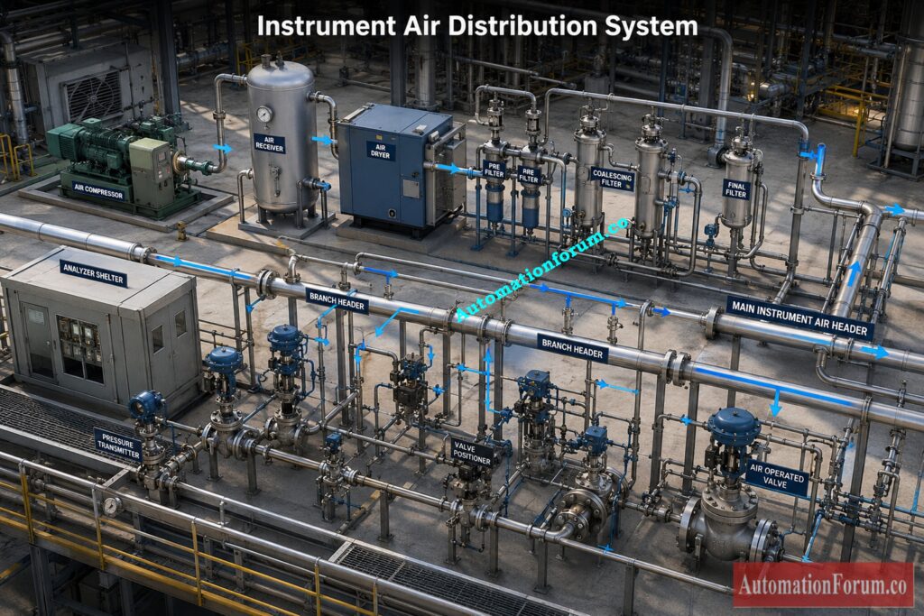
Definition of Instrument Air Header Pressure Drop
Instrument air header pressure drop is the loss of compressed air pressure when the air moves through an instrument air piping system. The primary reason of this pressure loss is friction between the air in motion and the pipe's inner wall, and extra resistance from bends, tees, valves, reducers, filters and other fittings.
Supply Pressure Versus Downstream Pressure
Every instrument air distribution system experiences some pressure loss. The objective of engineering design is to keep this pressure loss within acceptable limits so that all pneumatic instruments receive sufficient operating pressure.
The supply pressure is the pressure available at the compressor outlet and the downstream pressure is the pressure available at the end of the pipeline. The difference of these two figures is the entire pressure decrease over the header.
Factors Affecting Pressure Drop in Instrument Air Pipelines
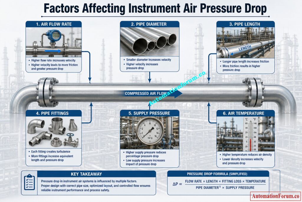
The pressure loss is a function of numerous technical parameters, such as:
- Instrument air flow rate
- Pipe internal diameter
- Equivalent pipeline length
- Supply pressure
- Air temperature
- Number of fittings and valves
Relationship Between Air Flow Pipe Diameter and Pressure Loss
Higher pipe diameter leads to a much lower pressure loss. Higher air flow and longer pipes lead to higher pressure loss. Selecting the correct pipe size is therefore one of the most important aspects of instrument air header design.
Refer the below link for the Air Consumption Calculator for Pneumatic Control Valves, Actuators and Instrument Air System Sizing
Why Instrument Air Pressure Drop Calculation Is Important During EPC Design
Pressure drop calculation is a standard engineering activity during every EPC project because it directly affects plant reliability, operating cost, and future system performance.
Selecting the Correct Instrument Air Pipe Size
Engineers use pressure drop calculations to determine the appropriate pipe diameter. Oversize pipe raises the expense of the project while undersize piping causes excessive pressure loss and bad performance of the instruments.
Ensuring Reliable Pneumatic Instrument Operation
Control valves, transmitters, analyzers and pneumatic actuators all require appropriate supply pressure to operate reliably. If the calculations are correct, every device will have enough air, even when the demand is at its highest.
Improving Control Valve Performance
Low air pressure results in a weak force of the actuator and a delayed response of the valve, poor accuracy of the location, increased response time and unstable control of the process.
Maintaining Fast Solenoid Valve Response
The low downstream pressure also causes a delay in the pneumatic signal transfer and an increase of the valve switching time especially during emergency shutdown operation.
Supporting Future Plant Expansion
Most EPC projects allow for spare capacity for future equipment expansions. Calculations of pressure drop evaluate whether the existing header can handle the increased air demand without major adjustments.
Improving Compressor Energy Efficiency
Compressors running at high discharge pressures due to high pressure losses increase power consumption and operating expenses. Correct compressed air pipeline calculation reduces energy losses.
Reducing Compressor Loading
Properly sized compressed air headers permit the compressor to operate closer to its design condition, reducing excessive loads and extending equipment life.
Lowering Maintenance Costs
The right size of pipeline will keep air velocity too high, noise, erosion of the pipe, carry over moisture and improve reliability of the system over the long run.
Meeting EPC Engineering Standards
EPC businesses do instrument air engineering calculations before construction starts to prove the distribution system meets the project specifications, client requirements and engineering standards.
Think You Know Compressors? Prove Your Engineering Skills Today: Advanced Quiz on Instrument Air Compressor Systems
Engineering Principles Behind the Instrument Air Header Pressure Drop Calculator
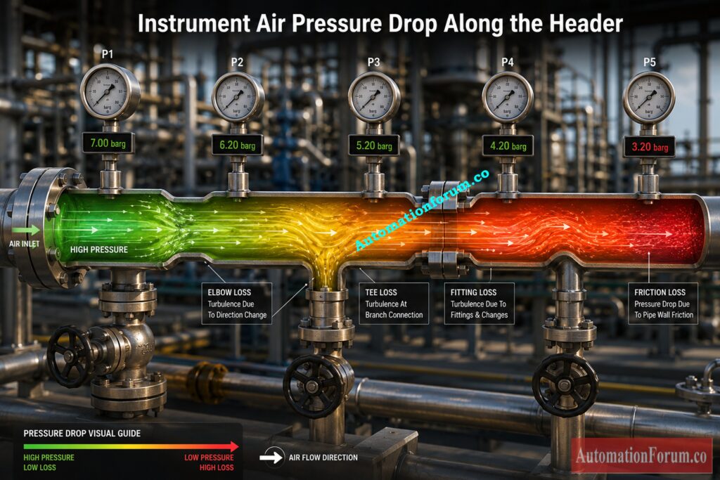
The Instrument Air Header Pressure Drop Calculator is based on actual compressed air engineering principles typically used in EPC design. It predicts pressure loss taking into account the combined effects of air flow, pipe size, pressure and pipeline length. This calculator will not do extensive hydraulic analysis, but will give a reliable preliminary estimate for instrument air distribution systems.
Understanding Equivalent Pipe Length
Equivalent pipe length is the overall effective length of the air pipeline. This is the actual straight pipe length plus the additional resistance caused by elbows, tees, valves, reducers and other fittings.
For example, an 80 m pipeline with a 30 percent fitting allowance is considered to have an equal length of 104 m. Using equal length gives a more realistic assessment of pressure loss than just considering the straight pipe.
Pipe Internal Diameter and Its Effect on Pressure Drop
Internal diameter is the actual flow path within the pipe. A slight increase in diameter can lead to a large reduction in pressure loss, because friction drops quickly with an increase in flow area.
Therefore, EPC engineers always utilize the pipe internal diameter for pressure drop calculations and not the nominal pipe size.
Free Air Delivery Explained
The calculator takes FAD as input since that is the flow rating standard used by compressor manufacturers and engineering requirements.
Difference Between Free Air Delivery and Actual Air Flow
The air demand is entered as Free Air Delivery however the volume of air moving inside the pipeline is smaller since compressed air has less volume at higher pressures.
The calculator transforms the standard flow into the actual operational flow for calculating the air velocity inside the pipeline. This provides a realistic evaluation of header performance.
Choose the Correct Air Preparation Components Without Costly Mistakes: FRL Unit Selection Procedure for On Off Instrumentation Control Valves
Absolute Pressure Versus Gauge Pressure
It is obtained by adding the gauge pressure to the ambient pressure.
Pressure drop calculations are done using absolute pressure since the density of compressed air is a function of operational pressure.
Gauge pressure: The pressure shown by compressor and pipeline pressure gauges. It is the pressure above atmospheric pressure . It is often given as barg , psig or kPag .
The calculator will convert the entered gauge pressure to absolute pressure automatically for the computations.
Importance of Atmospheric Pressure
Ambient pressure is the pressure of the ambient air at the location of the installation. The standard air pressure at sea level is about 1.013 bar.
The calculator allows engineers to adjust atmospheric pressure when projects are located at higher elevations where air density is lower.
Air Velocity in Instrument Air Distribution Systems
Air velocity is the speed at which compressed air travels through the pipeline.
Higher velocity increases friction losses, pressure drop, noise, and long term pipe wear. Lower speed means better system stability and lower energy use.
The calculator determines the air velocity according to the actual operating flow and the cross sectional area of the pipe.
Understanding Pressure Drop Percentage
The percentage pressure drop is the computed pressure loss divided by the available supply pressure.
This provides the engineer with a quick check to see if the pipe size chosen will meet the design parameters for the project. A smaller percentage usually means a more efficient instrument air network.
How Downstream Pressure Is Calculated
Downstream pressure is the pressure at the end of the header after subtracting all calculated pressure losses.
This value is important because every pneumatic instrument requires a minimum operating pressure for reliable performance. EPC engineers verify that the downstream pressure remains above the minimum required pressure under maximum air demand.
Every Design Engineer Needs This Powerful Excel Calculation Tool: Instrument Air System Design Excel Tool for Design Engineer
Instrument Air Header Pressure Drop Calculator Inputs Explained
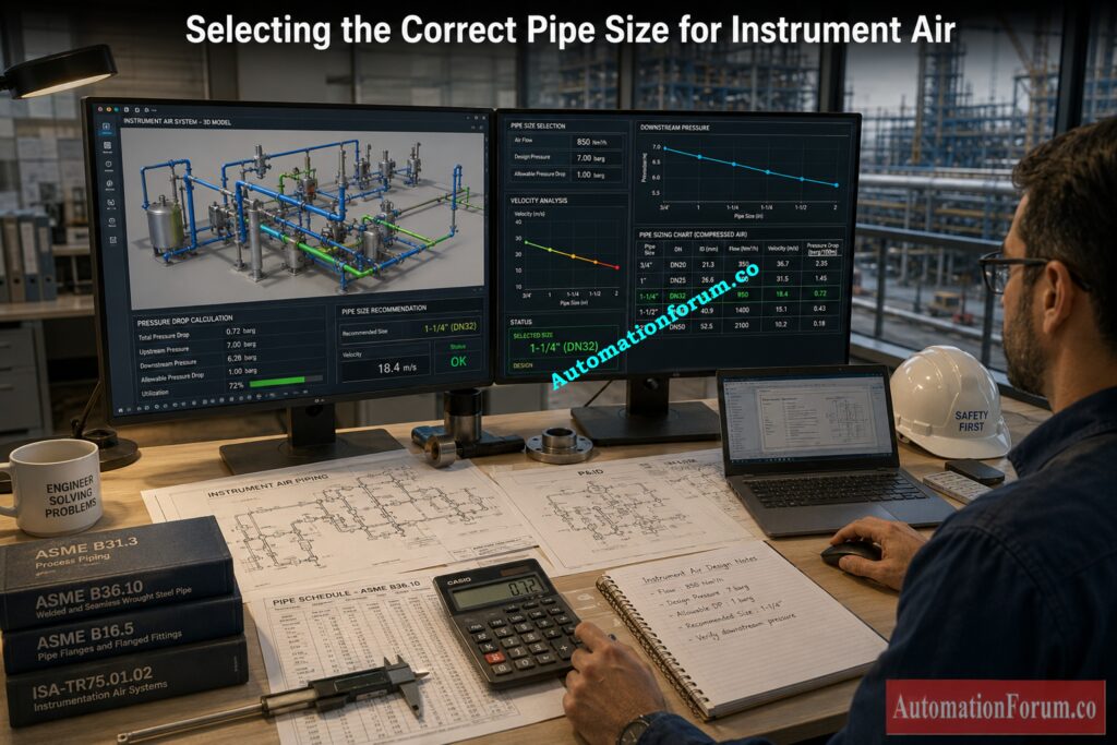
The Instrument Air Header Pressure Drop Calculator requires a few practical engineering inputs that are normally available during the design stage. These inputs characterize the working circumstances of the instrument air distribution system and have a direct impact on the computed pressure loss.
Instrument Air Flow Rate
The flow rate is the instrument air consumption of the header. It is usually given in Nm3/min, Nm3/h, SCFM or L/s as Free Air Delivery.
The value should include the simultaneous demand of all connected pneumatic devices along with an allowance for future expansion where required.
Compare the Industry's Most Trusted Valve Sizing Engineering Tools: Top 10 Control Valve Sizing Software Used in Process Industries
Straight Pipe Length
Pipe length is the actual straight distance between the air supply source and the most distant point on the header.
Longer pipelines create greater friction and therefore higher pressure loss.
Equivalent Pipe Length
Equivalent length includes the straight pipe length plus the additional resistance from elbows, tees, isolation valves, filters, regulators, and instrument take offs.
Pipe Diameter
Pipe diameter refers to the actual internal diameter through which compressed air flows.
Because pressure loss is highly sensitive to pipe diameter, selecting the correct size is one of the most effective ways to improve system performance.
Pipe Size Selection
The calculator provides standard Schedule 40 pipe sizes while also allowing engineers to enter a custom internal diameter for special applications.
This flexibility supports both standard and project specific piping selections.
Supply Pressure
Supply pressure is the compressed air pressure available at the beginning of the header.
Higher supply pressure generally reduces the percentage pressure loss but should always comply with plant operating requirements and equipment ratings.
Stop Selecting Wrong Valve Actions That Cause Process Problems: When to Choose Forward and Reverse Acting Control Valves for Design Engineer
Air Temperature
Air temperature affects air density and actual flow conditions inside the pipeline.
Although its influence on pressure drop is relatively small for typical instrument air systems, it is important for estimating realistic air velocity.
Atmospheric Pressure
Atmospheric pressure is normally left at the standard value of 1.013 bar but can be adjusted for installations located at higher elevations.
This improves the accuracy of absolute pressure calculations.
Pipe Fittings Allowance
These inputs characterize the working circumstances of the instrument air distribution system and have a direct impact on the computed pressure loss.
This approach provides a practical estimate during the EPC design stage.
Engineering Assumptions Used in the Calculator
The calculator assumes clean, dry compressed air flowing through commercial steel piping under normal industrial operating conditions. It is intended for preliminary engineering calculations and should be verified using detailed hydraulic analysis for large, complex, or critical compressed air systems.
Critical Utility Every Plant Depends on But Often Ignores: Importance of Instrument Air in Process Plant
Instrument Air Header Pressure Drop Calculator Outputs Explained
After the design inputs are run through the calculator, it will provide a number of engineering results that may be used to confirm the operation of the instrument air distribution system.
Calculated Pressure Drop
This is the overall pressure loss in the line and fittings due to friction. Shows whether the size of the chosen header is sufficient for the desired air flow.
Pressure Drop Percentage
The pressure loss is sometimes expressed as a percentage of the pressure of supply. Lower values often mean a more efficient instrument air header design.
Downstream Pressure
This is the estimated pressure available at the header end. This value is compared by engineers with the minimum pressure required for safe operation of pneumatic devices.
Never Select the Wrong Solenoid Valve for Critical Applications: Essential Checklist for Selecting the Right Solenoid Valve for Your Application
Equivalent Pipe Length
The calculator then returns the overall effective pipeline length including fitting losses. This gives the engineer an idea of the total resistance of the distribution network.
Air Velocity
The computed air velocity is the velocity of the compressed air through the header. If the velocity is too high it may cause noise, excessive friction loss and waste of energy.
Engineering Design Recommendation
Instrument Air Pressure Drop Formula Used in the Calculator
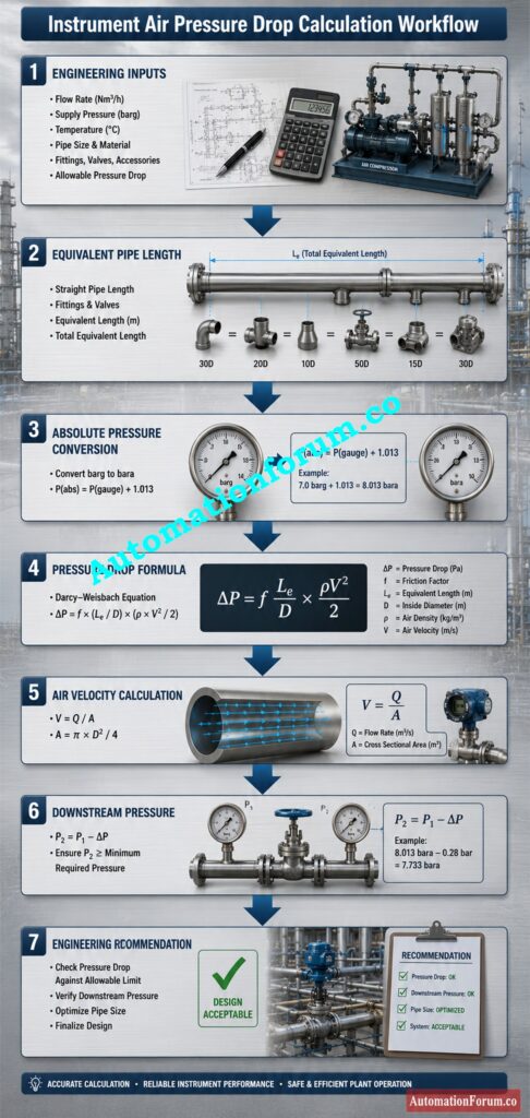
Engineering Variables Used in the Formula
The Instrument Air Header Pressure Drop Calculator is based on a widely recognized empirical compressed air pressure drop equation for preliminary pipeline size and pressure loss estimation as published in industrial compressed air engineering guides. It yields dependable results for typical instrument air distribution systems working within the recommended design limits.
The calculator uses an industry standard empirical equation which relates airflow, pipe diameter, equivalent pipe length, and upstream pressure, instead of doing a sophisticated compressible flow study.
The equation takes into account the following engineering variables:
Pressure Drop (ΔP)
The overall pressure loss due to friction of compressed air flowing in the pipeline. It is expressed in bar, kPa, psi and kg/cm².
Free Air Delivery (Q)
The total volume of compressed air delivered to the instrument air header at standard reference circumstances. More airflow means more frictional losses and more pressure drop.
Equivalent Pipe Length (L)
Total effective length of pipeline includes straight pipe and additional resistance due to fittings, elbows, tees, valves, and reducers.
Pipe Internal Diameter (D)
The actual internal diameter of the pipe. The pipe diameter has the biggest influence on the pressure drop. A modest increase in diameter will considerably minimize the frictional losses.
Absolute Supply Pressure (P)
The header inlet pressure was greater than absolute vacuum. Air is compressible , hence absolute pressure is a better basis for pressure drop calculations than gauge pressure .
Engineering Meaning of Each Variable
This formula provides an estimate of the pressure needed to push through the friction of the compressed air on the inner surface of the pipe. This allows engineers to easily compare various pipe sizes during EPC design without having to resort to comprehensive hydraulic simulations.
Supported Engineering Units
The calculator supports regularly used engineering units such as:
- Flow rate in Nm³/min, Nm³/h, SCFM, and L/s
- Pipe length in metres and feet
- Pressure in barg, kPag, and psig
- Temperature in °C and °F
- Pipe diameter in millimetres and inches
These automatic unit conversions facilitate calculations for foreign EPC projects.
Recommended Applications
The empirical equation is valid for:
- Instrument air headers
- Industrial compressed air distribution systems
- Preliminary EPC engineering
- Pipe sizing studies
- Feasibility evaluations
- Compressor distribution networks
Prevent Expensive Installation Rework with These Proven Field Practices: Avoiding Mistakes in Instrumentation Cable Tray Installation: A Guide for EPC Projects
Engineering Limitations of the Formula
The calculator gives precise initial estimates but engineers should be aware of its limits.
The equation is valid for clean, dry compressed air in commercial steel pipework under normal operating circumstances. It does not include large variations in elevation, atypical pipe roughness, leakage, transient flow circumstances or very complex distribution networks.
Preliminary results should always be checked by detailed hydraulic calculations and applicable engineering standards before final design approval for essential projects such as offshore facilities, LNG terminals, big compressor stations or high capacity compressed air systems.
Avoid Header Sizing Errors That Increase Operating Costs Significantly: Instrument Air Header Schedule
Instrument Air Header Design Guidelines for EPC Projects
Proper instrument air header design improves system reliability, minimizes compressor energy consumption, and ensures adequate pressure at every pneumatic instrument.
The following recommendations are widely adopted during EPC engineering.
Recommended Pressure Drop Limits
Properly designed instrument air headers enhance system reliability, save energy usage and provide enough pressure to all pneumatic instruments. Lower pressure losses improve control valve performance and reduce compressor operating costs.
Recommended Air Velocity Limits
Excessive air velocity increases friction, vibration, and noise. A moderate velocity promotes stable system operation and reduces long term pipe erosion.
Instrument Air Pipe Sizing Recommendations
Avoid selecting the smallest acceptable pipe simply to reduce installation cost. A slightly larger header often provides better long term reliability and lower operating expenses.
Planning for Future Expansion
Most process plants expand over time. Include spare capacity so additional instruments can be connected without replacing the main header.
Designing Main and Branch Headers
Total plant demand shall be carried on main headers, branch headers shall distribute air to individual process units. This configuration reduces pressure variations.
Every Process Engineer Should Understand This Critical Safety Study: What is HAZOP Study in Instrumentation Engineering for EPC Engineers in Process Industries
Reducing Pipe Fittings and Pressure Loss
Each elbow, tee, reducer and isolation valve adds to the pressure loss. Simplified piping layout improves the efficiency of the air distribution.
Position air receivers and distribution headers adjacent to important instrument loads where practical to reduce pressure drops.
Improving Compressor Efficiency
Lower pipeline resistance means that compressors can work at reduced discharge pressures, consuming less energy and prolonging equipment life.
Verifying Downstream Pressure
Always check that the computed downstream pressure is above the minimum operating pressure of all connected pneumatic devices.
Master Reliable Compressed Air Networks with Proven Design Practices: Design of Instrument Air Systems
Practical Instrument Air Header Pressure Drop Calculation Example
Below example depicts how an EPC engineer uses the Instrument Air Header Pressure Drop Calculator at the design stage.
Design Conditions
- Instrument air demand: 6 Nm³/h
- Straight pipe length: 80 m
- Pipe fittings allowance: 30 percent
- Header size: 1 inch Schedule 40
- Internal diameter: 26.6 mm
- Supply pressure: 7 barg
- Air temperature: 25°C
- Atmospheric pressure: 1.013 bar
These numbers are in agreement with the default engineering inputs of the calculator.
Step 1 Calculate Equivalent Pipe Length
The fitting allowance is added to the effective overall length of the pipeline.
Straight pipe length = 80 m
Equivalent pipe length = 104 m
Step 2 Determine Absolute Pressure
The calculator first converts the gauge pressure to absolute pressure, and then calculates the pressure loss.
Crack Your Next EPC Interview with Confidence and Ease: Instrumentation Designer Interview Questions and Answers for EPC Projects
Step 3 Calculate Pressure Drop
The calculator gives an estimate of the empirical compressed air equation:
- Total pressure drop
- Pressure drop percentage
- Air velocity
- Downstream pressure
Step 4 Verify Air Velocity
The calculated air velocity is verified with good engineering practice to verify the appropriateness of the specified pipe diameter.
Engineering Recommendation
The results suggest that the selected header size offers an acceptable pressure loss and sufficient downstream pressure for normal operation of the pneumatic instrument. If future growth results in a major increase in air demand, the next bigger pipe size should be selected, both to further reduce pressure drop and to provide long term system flexibility.
Start with These Essential Fundamentals Before Designing Any Air System: BASICS OF AN INSTRUMENT AIR SUPPLY SYSTEM
Applications of the Instrument Air Header Pressure Drop Calculator
The Instrument Air Header Pressure Drop Calculator is used throughout the engineering lifecycle from concept design to plant operation.
Typical applications include:
- Oil and gas production facilities
- Petrochemical plants
- Chemical processing plants
- Power generation stations
- Water and wastewater treatment plants
- Food and beverage manufacturing
- Pharmaceutical production facilities
- Paper and pulp industries
- Steel manufacturing plants
- Mining operations
- LNG terminals
- Offshore production platforms
- General process industries
It is widely used by instrumentation engineers, piping engineers, mechanical engineers, EPC consultants, commissioning teams, and maintenance engineers to evaluate compressed air distribution systems quickly and improve overall instrument air engineering efficiency.
Reduce Downtime Faster Using This Practical Reliability Engineering Calculator: Mean Time To Repair (MTTR) Calculator for Process Instrumentation Downtime Analysis
Common Instrument Air Header Design Mistakes to Avoid
Even a well designed compressed air system can experience performance issues if basic engineering principles are overlooked. The following are the common errors done in EPC design and plant changes.
Selecting an Undersized Header
To save down installation expense, a smaller pipe is usually chosen which results in high pressure loss, high air velocity and insufficient pressure at field sensors. Header sizes should always be based on the greatest predicted air demand.
Ignoring Fitting Losses
Elbows, tees, isolation valves, filters and regulators all oppose flow. The straight pipe length alone is not sufficient to calculate the actual pressure drop. Include equivalent pipe length during every design calculation.
Ignoring Future Expansion
Many plants add new control valves, analyzers, and pneumatic instruments after commissioning. Designing the header without any extra capacity may involve expensive plumbing adjustments later.
Using Incorrect Pressure Units
Confusing gauge pressure with absolute pressure is a typical engineering mistake. For best results, always calculate pressure drops using absolute pressure.
Using Nominal Instead of Internal Diameter
The nominal pipe size is a designation of the pipe and does not describe the actual flow area. Use pipe interior diameter for pressure loss calculations.
Ignoring Air Temperature
Air density and real flow conditions are temperature dependent. Although its effect is usually small, including temperature improves the accuracy of air velocity calculations.
Allowing Excessive Air Velocity
High velocity increases friction, vibration, noise, and long term pipe wear. Verify that the calculated velocity remains within good engineering practice.
Incorrect Equivalent Length
Using only the straight pipe length ignores the resistance created by fittings. Include a realistic fittings allowance or calculate the equivalent length of each fitting.
Not Verifying Compressor Capacity
A properly sized header cannot compensate for an undersized compressor. Ensure that the compressor is capable of delivering the requisite Free Air Delivery at the specified value of operating pressure.
Discover the Real Reason Your Loop Reads Beyond Range: Why Is My Pressure Transmitter Showing 22 mA? Complete Troubleshooting Guide for Instrument Engineers
Best Engineering Practices for Instrument Air Distribution System Design
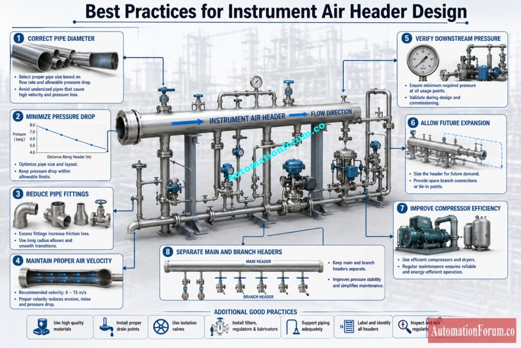
The following are the general guidelines for reliable design of instrument air distribution system by EPC companies.
- Calculate the pressure drop at the early design stage.
- Size headers using maximum simultaneous air demand.
- Include an allowance for future plant expansion.
- Use equivalent pipe length instead of straight pipe length alone.
- Always utilize the true internal pipe diameter.
- Keep air velocity within reasonable limits throughout the system.
- Reduce bends and fittings as much as possible.
- Isolate main headers from branch distribution lines.
- Provide isolation valves for easy maintenance.
- Check the furthest instrument for downstream pressure.
- Select the capacity of the compressor with a reasonable operating margin.
- Review pressure drop with any further instrument additions.
- Compare preliminary calculations with design criteria of the project.
- Perform extensive hydraulic analysis for crucial systems validation.
- Verify final design meets applicable technical standards and project specifications
Frequently Asked Questions About Instrument Air Header Pressure Drop Calculator
What is an Instrument Air Header Pressure Drop Calculator?
It is a design tool for estimating pressure loss, downstream pressure and air velocity in compressed air distribution systems from conventional design inputs.
Why is pressure drop important in instrument air systems?
The high pressure drop limits the working pressure available to pneumatic instruments, which affects reliability and control performance.
What causes pressure loss in an instrument air pipeline?
The main causes of pressure loss are pipe friction, extensive piping lines, couplings, valves, reducers and high air velocity.
How can pressure drop be reduced?
Use larger diameter pipe, minimize piping runs, minimize fittings, keep air velocity in the distribution system reasonable.
What is equivalent pipe length?
Equivalent length is the length of straight pipe plus the added resistance due to fittings, valves, elbows, and tees.
Why is internal pipe diameter used instead of nominal pipe size?
The pressure loss depends on the actual flow area within the pipe and therefore the internal diameter is the correct engineering parameter for calculations.
Why is absolute pressure used in the calculation?
Since the density of compressed air is pressure-dependent, calculating the pressure drop with absolute pressure will be more accurate than using gauge pressure.
What is Free Air Delivery?
Free Air Delivery is the compressor output referenced to standard atmospheric conditions and is commonly used for compressed air system design.
Why is air velocity calculated?
Air velocity helps the engineer to know if the pipe size he has chosen will allow for efficient, quiet and reliable distribution of compressed air.
Can this calculator be used for preliminary EPC design?
Yes. It is used for preliminary engineering studies and pipe sizing before detailed hydraulic confirmation for critical projects.
Prevent Frozen Impulse Lines Before Winter Stops Your Process: Impulse Line Freezing Risk and Heat Tracing Calculator for Instrumentation Engineers
Conclusion: Final Thoughts on Instrument Air Header Pressure Drop Calculator
An adequately constructed instrument air distribution system is an important need for reliable plant operation. Accurate pressure drop calculations aid engineers in correctly sizing headers, maintaining enough downstream pressure, enhancing pneumatic instrument operation and minimizing compressor energy usage.
Instrument Air Header Pressure Drop Calculator is a quick and handy way to estimate pressure drop, equivalent pipe length, downstream pressure and air velocity during EPC engineering. Evaluation of multiple design options before construction allows engineers to optimize instrument air header design, improve long term system reliability and avoid costly modifications after commissioning.
The calculator is a great tool for preliminary engineering, but final design must always be verified against applicable engineering standards, detailed hydraulic calculations and project specific design requirements to ensure safe, efficient and dependable operation throughout the plant lifecycle.
Refer the below link for the What Causes 80% of Instrument Failures in Industry? Top 10 Causes and Prevention Methods
